

Page 1
www.dalsemi.com
DS2227
Flexible NV SRAM Stik
FEATURES
Flexibly organized as 128k x 32, 256k x 16,
or 512k x 8 bits
Data retention >10 years in the absence of
V
CC
Nonvolatile circuitry transparent to and
independent from host system
Automatic write protection circuitry
safeguards against data loss
Separate chip enables allow access by byte,
word, or long word
Fast access times: 70 ns, 100 ns, or 120 ns
Unlimited write cycles
Read cycle time equals write cycle time
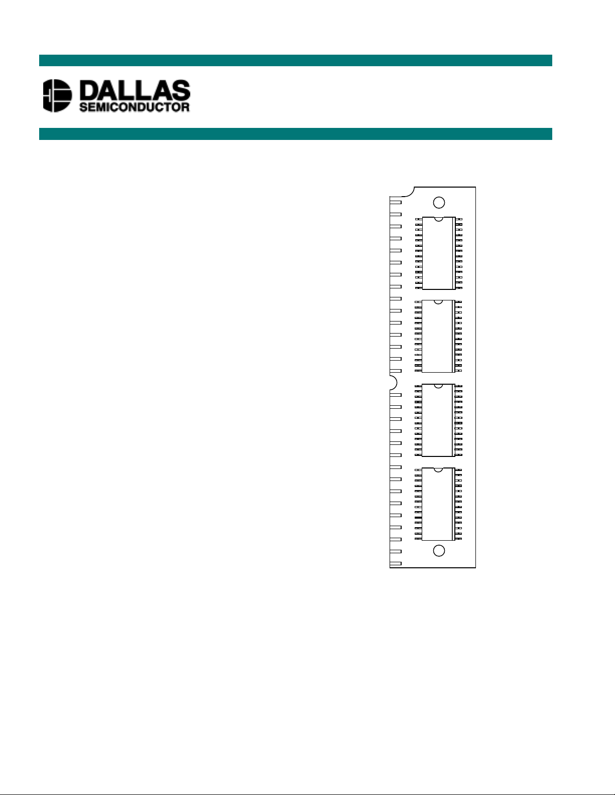
Employs popular JEDEC standard 72-position
SIMM connection scheme
Lithium energy source is electrically
disconnected to retain freshness until power is
applied for the first time
PIN ASSIGNMENT
SRAM
SRAM
SRAM
1M
1M
1M
SRAM
1M
721
72-Pin SIP STIK
DESCRIPTION
The DS2227 Flexible NV SRAM Stik is a self-contained 4,194,304-bit nonvolatile static RAM which can
be flexibly organized as 128k x 32 bits, 256k x 16 bits, or 512k x 8 bits. The nonvolatile memory contains
all necessary control circuitry and lithium energy sources to maintain data integrity in the absence of
power for more than 10 years. The DS2227 employs the popular JEDEC standard 72-position SIMM
connection scheme requiring no additional circuitry.
OPERATION
The DS2227 Flexible NV SRAM Stik is used like any standard static RAM. All nonvolatile circuitry is
transparent to the user. The flexibility of the part is achieved by providing separate read, write, and chip
1 of 10 112099
Page 2

DS2227
select pins for each of the four banks of onboard memories (see Figure 1). For operation as a 512k x 8 NV
SRAM Stik, tie all data lines from each bank together (i.e., all D0s together, all D1s together, etc.). Read
enables and write enables are also tied together. For operation as a 256k x 16 NV SRAM Stik, tie the data
lines from two banks together. Chip enables, read enables, and write enables from these banks are also
tied together. Connection to the DS2227 is made by using an industry-standard, 72-position SIMM socket
DS9072-72V (AMP part number 821824-8). These SIMM sockets are also available in perpendicular,
TM
inclined, or parallel mount, depending on the height available. See the DS907x SipStik
connectors
available from Dallas Semiconductor.
READ MODE
The DS2227 executes a read cycle wheneve r WE (Write Enable) is inactive (high) and CE (Chip Enable)
and OE (Output Enable) are active (low). The unique address specified b y the 17 address inputs (A0 - A16)
defines which byte of data is to be accessed. Valid data will be available to the eight data I/O pins within
t
(access time) after the last address input signal is stable, providing that CE and OE access times ar e
ACC
also satisfied. If OE and CE times are not satisfied, then data access must be measured from the later
occurring signal (CE or OE ) and the limiting parameter is either tCO for CE or tOE for OE rather than
address access.
WRITE MODE
The DS2227 is in the write mode whenever both WE and CE signals are in the active (low) state after
address inputs are stable. The latter occurring falling edge of CE or WE will determine the start of the
write cycle. The write cycle is terminated by the earlier rising edge of CE or WE . All address inputs must
be kept valid throughout the write cycle. WE must return to the high state for a minimum recovery time
(tWR) before another cycle can be initiated. The OE control signal should be kept inactive (high) during
write cycles to avoid bus contention. However, if the output bus has been enabled (CE and OE active)
then WE will disable the outputs to t
from its falling edge.
ODW
DATA RETENTION MODE
The DS2227 provides fully functional capability for VCC greater than 4.5 volts and guarantees write
protection for VCC less than 4.25 volts. Data is maintained in the absence of VCC without any additional
support circuitry. The DS2227 constantly monitors V
SRAM automatically write-protects itself, all inputs become “don’t care” and all outputs become high
impedance. As VCC falls below approximately 3.0 volts, a power switching circuit connects a lithium
energy source to RAM to retain data. During power-up, when VCC rises above approximately 3.0 volts,
the power switching circuit connects the external VCC to RAM and disconnects the lithium energy source.
Normal RAM operation can resume after VCC exceeds 4.5 volts.
The DS2227 checks lithium status to warn of potential data loss. Each time that V
the DS2227, the battery voltage is checked with a precision comparator. If the battery supply is less than
2.0 volts, the second memory access to the device is inhibited. Battery status can, therefore, be
determined by a three-step process. First, a read cycle is performed to any location in memory, in order to
save the contents of that location. A subsequent write cycle can then be executed to the same memory
location, altering data. If the next read cycle fails to verify the written data, then the battery voltage is less
than 2.0V and data is in danger of being corrupted.
The DS2227 also provides battery redundancy. In many applications data integrity is paramount. The
DS2227 provides two batteries for each SRAM and an internal isolation switch to select between them.
During battery backup, the battery with the highest voltage is selected for use . If one battery fails, the
other automatically takes over. The switch between batteries is transparent to the user.
2 of 10
. Should the supply voltage decay, the NV
CC
power is restored to
CC
Page 3
DS2227
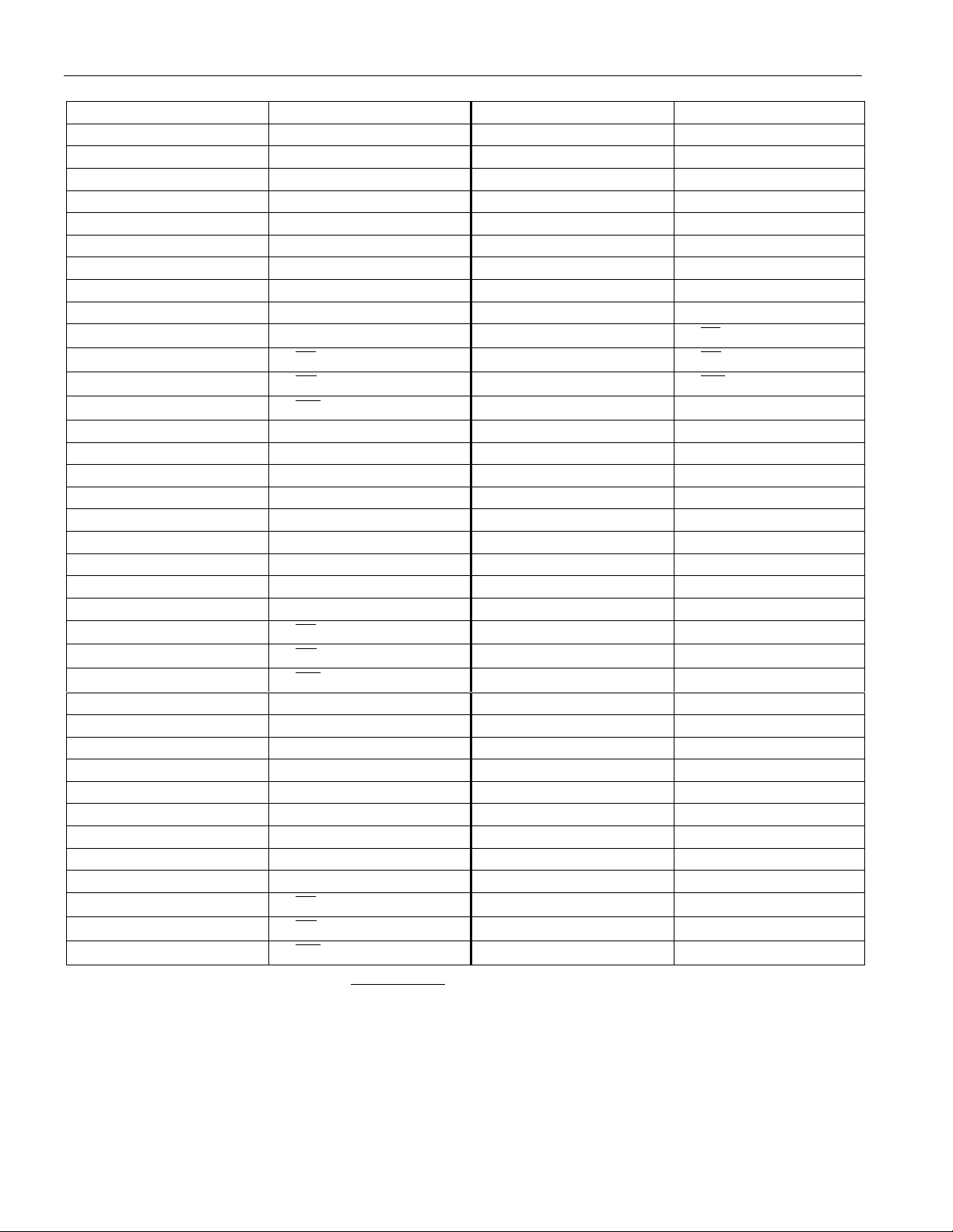
PIN DESCRIPTION Table 1
PIN SIGNAL NAME PIN SIGNAL NAME
1VCC38 4-D0
2 1-D0 39 4-D1
3 1-D1 40 4-D2
4 1-D2 41 4-D3
5 1-D3 42 4-D4
6 1-D4 43 4-D5
7 1-D5 44 4-D6
8 1-D6 45 4-D7
91-D746NC
10 NC 47
11
12
13
1-CE
1-
OE
1-WE
48
49
50 GND
14 2-D0 51 V
15 2-D1 52 A0
16 2-D2 53 A1
17 2-D3 54 A2
18 2-D4 55 A3
19 2-D5 56 A4
20 2-D6 57 A5
21 2-D7 58 A6
22 NC 59 A7
23
24
25
2-CE
2-OE
2-WE
60 A8
61 A9
62 A10
26 3-D0 63 A11
27 3-D1 64 A12
28 3-D2 65 A13
29 3-D3 66 A14
30 3-D4 67 A15
31 3-D5 68 A16
32 3-D6 69 NC
33 3-D7 70 NC
34 NC 71 NC
35
36
37
3-CE
3-OE
3-WE
72 GND
NOTE: Leave all pins marked as NC unconnected.
4-CE
4-OE
4-
WE
CC
3 of 10
Page 4

SCHEMATIC (1 CELL) Figure 1
DS2227
4 of 10
Page 5

DS2227
ABSOLUTE MAXIMUM RATINGS*
Voltage on Any Pin Relative to Ground -0.3V to +7.0V
Operating Temperature 0°C to 70°C
Storage Temperature -40° to +85°C
* This is a stress rating only and functional operation of the device at these or an y other conditions above
those indicated in the operation sections of this specification is not implied. Exposure to absolute
maximum rating conditions for extended periods of time may affect reliability.
RECOMMENDED DC OPERATING CONDITIONS (0°C to 70°C)
PARAMETER SYMBOL MIN TYP MAX UNITS NOTES
Power Supply Voltage V
Input High Voltage V
Input Low Voltage V
CC
IH
IL
4.5 5.0 5.5 V
2.2 V
CC
V
0 +0.8 V
DC ELECTRICAL CHARACTERISTICS (0°C to 70°C; VCC = 5V ±10%)
PARAMETER SYMBOL MIN TYP MAX UNITS NOTES
Input Leakage Current I
I/O Leakage Current I
Output Current @ 2.4V I
Output Current @ 0.4V I
Operating Current I
Write Protection Voltage V
IL
LO
OH
OL
CC
TP
-1.0 +1.0 µA
-5.0 +5.0 µA
-1.0 mA
2.0 3.0 mA
60 280 mA
4.25 4.37 4.5 V
CAPACITANCE (TA = 25°C)
PARAMETER SYMBOL MIN TYP MAX UNITS NOTES
Input Capacitance C
Output Capacitance C
IN
OUT
20 40 pF
510pF
5 of 10
Page 6

AC ELECTRI CAL C HARACTERISTICS
DS2227-70 DS2227-100 DS2227-120
PARAMETER SYMBOL
MIN MAX MIN MAX MIN MAX
DS2227
UNITS NOTES
Read Cycle Time t
Access Time t
OE to Output
Valid
CE to Output
Valid
OE or CE to
Output Active
Output High Z
from Deselection
Output Hold from
Address Change
Write Cycle Time t
Write Pulse Width t
Address Setup
Time
Write Recovery
Time
Output High Z
from WE
Output Active
from WE
Data Setup Time t
Data Hold Time
from WE
RC
ACC
t
OE
t
CO
t
COE
t
OD
t
OH
WC
WP
t
AW
t
WR
t
ODW
t
OEW
DS
t
DH
70 100 120 ns 10
70 100 120 ns 10
35 50 60 ns 10
70 100 120 ns 10
555 ns10
25 35 40 ns 10
555 ns10
70 100 120 ns 10
55 75 90 ns 3,10
000 ns10
20 20 20 ns 10
25 35 40 ns 10
5 5 5 ns 8,10
30 40 50 ns 4,10
20 20 20 ns 4,5,10
6 of 10
Page 7

READ CYCLE
SEE NOTE 1
WRITE CYCLE 1
DS2227
SEE NOTES 2, 3, 4, 5, 6, 7 AND 8
WRITE CYCLE 2
SEE NOTES 2, 3, 4, 5, 6, 7 AND 8
7 of 10
Page 8

POWER-UP/POWER-DOWN CONDITION
POWER-DOWN/POWER-UP TIMING
PARAMETER SYMBOL MIN TYP MAX UNITS NOTES
DS2227
CE at V
Before
IH
Power-down
VCC Slew from 4.5V to 4.25V
(CE at VIH )
VCC Slew from 0V to 4.5V
(CE at VIH )
CE at V
after Power-up
IH
PARAMETER SYMBOL MIN TYP MAX UNITS NOTES
Expected Data Retention t
t
t
REC
PD
t
F
t
R
DR
0µs
300 µs
0µs
2 80 125 ms
(TA = 25°C)
10 years
8 of 10
Page 9

DS2227
NOTES:
1. WE is high for a read cycle.
2. OE = VIH or VIL. If OE = VIH during write cycle, the output buffers remain in a high impedance
state.
3. t
is specified as the logical AND of CE and WE .
WP
4. tDH, tDS are measured from the earlier of CE or WE going high.
5. t
is measured from WE going high. If CE is used to terminate the write cycle then tDH = 20 ns.
DH
6. If the CE low transition occurs simultaneously with or later than the WE low transition, the
output buffers remain in a high impedance state in this period.
7. If the CE high transition occurs prior to or simultaneously with the WE high transition, the output
buffers remain in a high impedance state in this period.
8. If th e WE is low or the WE low transition occurs prior to or simultaneously with the CE low
transition, the output buffers remain in a high impedance state in this period.
9. Each DS2227 is marked with a 4-digit date code AABB. AA designates the year of manufacture.
BB designates the week of manufa cture. The minimum expected tDR is defined as starting at the
date of manufacture.
10. Timings are valid only when CE is tied low.
DC TEST CONDITIONS
Outputs Open
Cycle = 200 ns
All Voltages are Referenced to Ground
AC TEST CONDITIONS
Output Load: 100 pF + 1TTL gate
Input Pulse Levels: 0 - 3.0 V
Timing Measurements Reference Levels:
Input - 1.5V
Output - 1.5V
Input Pulse Rise and Fall Times: 5 ns
ORDERING INFORMATION
9 of 10
Page 10

DS2227 72-PIN SIP STIK
DS2227
NOTE: DIMENSIONS ARE SHOWN IN INCHES.
DIM
A
B
C
D
E
F
G
H
I
J
K
L
M
N
O
P
72-PIN
MIN MAX
4.245 4.255
3.979 3.989
0.845 0.855
0.395 0.405
0.245 0.255
0.050 BASIC
0.075 0.085
0.245 0.255
1.750 BASIC
0.120 0.130
2.120 2.130
2.245 2.255
0.057 0.067
- 0.140
- 0.140
- 0.054
10 of 10
 Loading...