

Page 1
DPM 970 Digital AC Voltmeter Module
A 3 ½ digit LCD panel meter, featuring 19mm (0.75“) digit height and LED backlighting, the DPM 970 is a true RMS voltage and current meter with 500V a.c.
➁
(2kV ) and2mAfull scale readings asstandard. By changingthevalue of scalingresistorsor adding a shunt,thismodule will measure mosta.c.voltages and
currents. The DPM 970 features auto-zero and suppression of d.c. offset voltage. The digitalhold function freezes the last displayed reading. Calibration is
achieved via two multi-turn potentiometers for offset and scale. Connection to the meter is via screw terminals. The module is housed in a robust carrier
which can be bolted in placeor panelmountedusingthebezel, window and clips provided.
19mm (0.75“) Digit Height
Screw Terminal Connections
Digital Hold
500V a.c. (2kV ) Full Scale Reading
➁
Measures Voltage and Current
LED Backlighting
SCALING
The value of the three scaling resistors RA1, RA2 and RB may be
altered inorder tochangethefull scale reading (F.S.R.) of themeter
- see table.
voltage/current, short circuit ACV and COMandadjust the ZERO
potentiometer.
CAL potentiometer.
Required F.S.R. RA2 RBRA1
200mV 0R 0R Open
2V 910k 100k
20V 1M 10k
200V 1M 1k
2kV (factory default) 464K 536K 100R
2mA (factory default) - - 100R
20mA - - 10R
200mA - - 1R
2A - - 0.1R
20A - - 0.01R
NOTE
➀
➁
➂
➃
Other scaling factors can be achieved via the correct selection of
RA1, RA2 andRBvalues.
To ensure that the meter reads "000" with zero input
The meter willneedre-calibrationby adjusting the
➀
➀
➀
➀
0R
0R
0R
➀ ➁
➂
➂
➂
➂
➂ ➃
Use inputs ACV and COM for measuring voltage.
For measuring voltages above 500V RMS, external scaling
resistors must be used.
Use inputs ACI and COM for measuring current.
We recommend the use of a current transformer when
measuring in excess of 10 Amps. Consult current transformer
manufacturer’sdata for connectionsandrecommendations.
Stock Number
Standard Meter DPM 970
Specification Min. Typ. Max. Unit
Accuracy (overall error) * 0.5 1.5 % (±2 count)
Full scale reading ** 0 1999 V
Resolution 1 V
Sample rate 3 samples/sec
Operating temperature range 0 50 °C
Temperature s 200 ppm/°C
tability
Frequency range (input voltage) 15 15k Hz
Input impedance (2kV range) 1 M
DC Supply voltage 7.5 9 14 V d.c.
Supply current (Backlighting off) 1.5 mA d.c.
Supply current (Backlighting on) 50 mA d.c.
@ 5Vd.c.
* To ensure maximum accuracy, re-calibrate periodically.
** Maximum safe input voltage across the ACV and COM terminals is 500V .
If voltages to be measured exceed 500V , then fit scaling resistors
RMS
RMS
RMS
Ω
RMS
externally to the module.
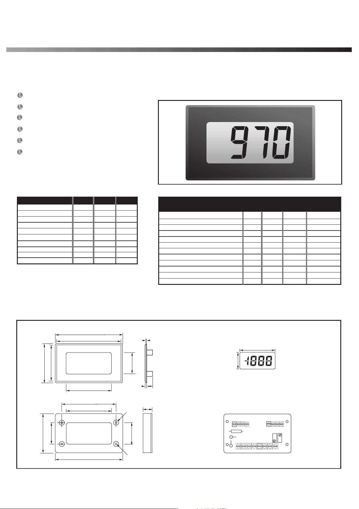
DIMENSIONS All dimensions in mm (inches)
40.5 (1.59)
44.0 (1.73)
24.0 (0.94)
39.0 (1.54)
76.0 (2.99)
72.5 (2.85)
51.0 (2.01)
61.5 (2.42)
51.0 (2.01)
71.5 (2.81)
24.0 (0.94)
Ø5.7
(0.22)
24.5 (0.96)
Ø3.0
(0.12)
a
b
d
WEBSITE: http://www.lascarelectronics.com/
a. 1.0 (0.04)
b. 2.0 (0.08)
c. 6.5 (0.26)
d. 11.5 (0.45)
c
Panel cut-out 72 x 40 (2.83 x 1.57)
Maximum panel thickness 3mm (0.12).
51 (2.01)
24 (0.94)
Display in Test Mode
TST
XDP
ALM
HLD
RB
RA2
REAR
VIEW
RA1
ACV ACI COM COM V+ V- LP- LP+
V+
DP1
DP2
CAL ZERO
DP3
Page 2
LASCAR ELECTRONICS LTD.
MODULE HOUSE, WHITEPARISH,
TEL: +44 (0)1794 884567 FAX: +44 (0)1794 884616
WILTSHIRE SP5 2SJ UK
E-mail: [email protected]
LASCAR ELECTRONICS INC.
3750 West 26th Street,
TEL: +1 (814) 835 0621 FAX: +1 (814) 838 8141
Erie, PA 16506 USA
E-mail: [email protected]
LASCAR ELECTRONICS (HK) LIMITED
FLAT C, 5/FL., LUCKY FTY. bldg., 63-65 HUNG TO ROAD
KWUN TONG, KOWLOON, HONG KONG
TEL: +852 2797 3219 FAX: +852 2343 6187
E-mail: [email protected]
SCREW TERMINAL FUNCTIONS
ACV Alternating voltage measurement input, acceptsupto500Va.c. By changingthevaluesof scalingresistorsRA1,RA2 andRB,othervoltageand
COM Return linefor voltagemeasurement input(ACV) orcurrentmeasurement(ACI) input.
COM Return linefor voltagemeasurement input(ACV) orcurrentmeasurement(ACI) input.
LP+ PositivesupplyforLED backlighting.
HLD Digital Hold option. Connect to V+ toholdlastdisplayedreadingindefinitely.
ALM Alarm “!”annunciator.ConnecttoXDPto display.
XDP Annunciator drive waveform. Used to drive alarm annunciator (ALM) if required.
current ranges can be achieved.Tomeasureinexcessof 500Va.c., removeRA1,RA2 andRBfrom themeterandexternally; linkRA1andRA2 on
the meter. See scalingtableforsuitable valuesforRA1,RA2 andRB.
ACI Alternating current measurement input.
See Scaling tableforsuitablevaluesforshuntresistor RB.
V+ Positivepowersupplyinput.
V- Negative powersupplyinput.
LP- NegativesupplyforLED backlighting.
TST Connect to V+ to display all segmentsexceptdecimal pointsandannunciators.
It should notbeoperatedformorethana fewsecondsasthe DCvoltageapplied
to the LCDmay“burn”thedisplay. This connection is normally at 5V below V+
and is thegroundforthedigitalsectionof themeter.
V+ Auxilliary V+ forconnectionstodecimalpointsDP1,DP2or DP3.
DP1 199.9 Connect toV+to displayrequireddecimalpoint.
DP2 19.99 Connect toV+to displayrequireddecimalpoint.
DP3 1.999 Connect toV+to displayrequireddecimalpoint.
SAFETY WARNING
To complywith the LowVoltage Directive (LVD 93/68/EEC),input voltages to themodule’s connectors mustnot exceed 500VRMS. Ifvoltages to bemeasured
exceed 500VRMS, then fit scalingresistors externally to the module. If the mains power supply isconnected tothe module, thenall themodule’s connectors
must be considered to be floating at mains potential. Consequently due caution must be exercised when connecting to the module’s connector functions
under theseconditions. The user must ensurethatthe incorporation oftheDPM into theuser’s equipment conforms totherelevant sections ofBS EN 61010
(Safety Requirements for Electrical Equipment forMeasuring, ControlandLaboratory Use).
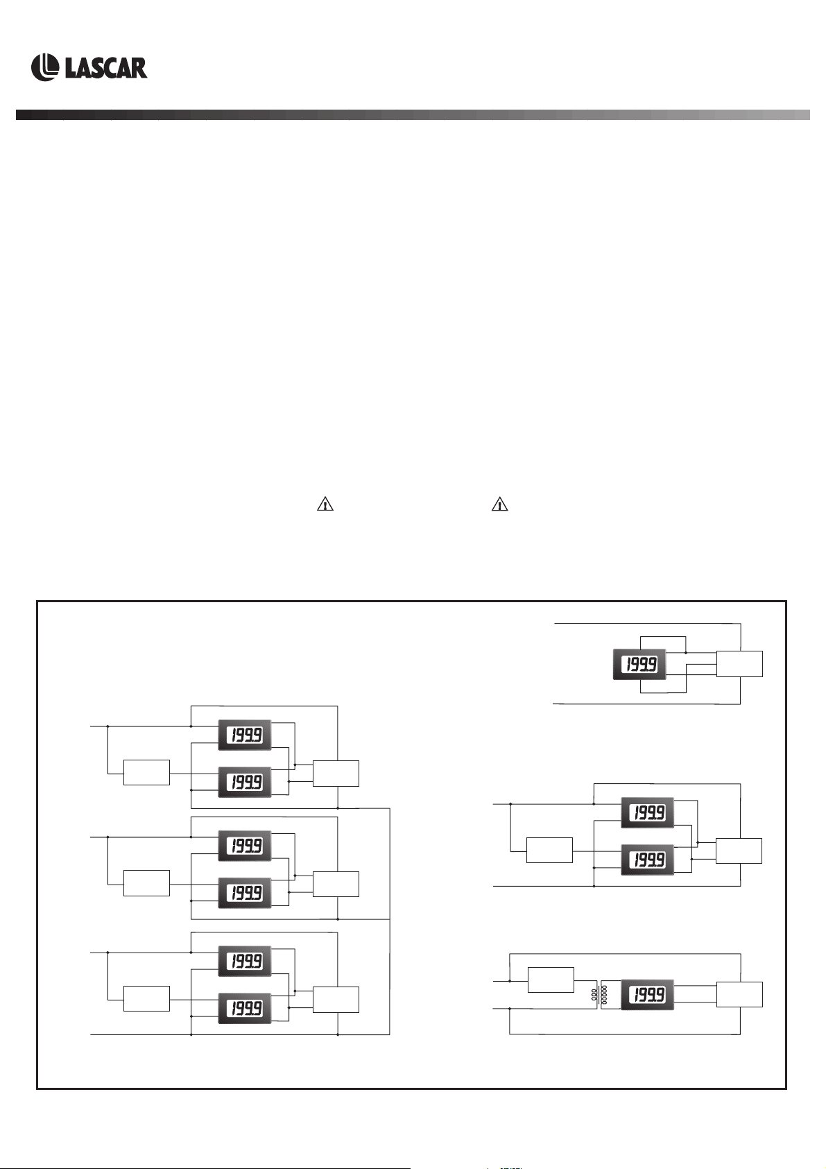
APPLICATIONS
WARNING : Do not apply in excess of 500V a.c. to the meter.
Voltage
Current
Voltage
Current
Voltage
Current
V+
V-
V+
V-
V+
V-
V+
V-
V+
V-
V+
V-
+5V
-5V
+5V
-5V
+5V
-5V
110/240V
PSU 303
0V
110/240V
PSU 303
0V
110/240V
PSU 303
0V
Phase 1
Phase 2
Phase 3
Neutral
Load
Load
Load
ACV
COM
ACI
COM
ACV
COM
ACI
COM
ACV
COM
ACI
COM
3-Phase Current and Voltage
Measurement
Phase
Neutral
Phase
Neutral
Phase
LP+
V+
V-
LP-
Neutral
Powering the LED backlighting on a DPM 970
from the PSU 303's +5V and COM outputs.
Voltage
Load
ACV
COM
ACI
COM
Current
V+
V-
V+
V-
Single Phase Current and Voltage
Measurement
Load
ACI
CT
COM
V+
V-
Using a current transformer (CT) to
measure currents in excess of 10A a.c.
+5V
COM
-5V
+5V
-5V
+5V
-5V
110/240V
PSU 303
0V
110/240V
PSU 303
0V
110/240V
PSU 303
0V
Specifications liable to change without prior warning DPM 970 Issue 5 August/2002 M.C. Applies to DPM 970/4
 Loading...