

Page 1
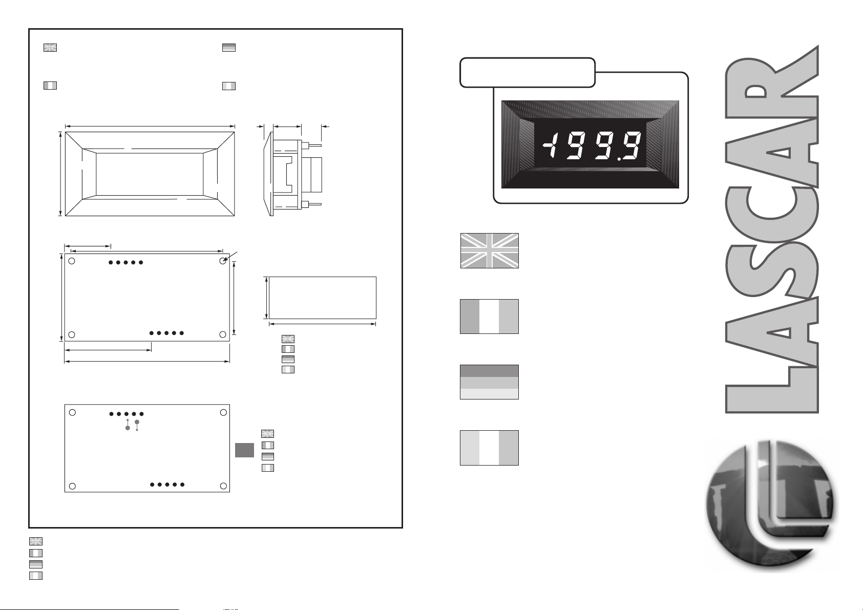
DIMENSIONS
All dimensions in mm (inches)
Panel cut-out 68 x 33 (2.68 x 1.30)
DIMENSIONS
Toutes les dimensions sont en mm (pouces)
Découpe panneau 68 x 33 (2,68 x 1,30)
ABMESSUNGEN
Alle Abmessungen in mm (Zoll)
Einbauausschnitt
68 x 33 (2,68 x 1,30)
DIMENSIONI
Tutte ledimensioni sonoespresse in mm(pollici)
Finestrapannello
68 x 33(2,68 x1,30)
DPM 40
36 (1.30)
33 (1.30)
24 (0.94)
+5V
30.5 (1.20)
COM
72 (2.83)
62 (2.44)
IN HI
IN LO
68 (2.68)
bc
a
a. 4.0 (0.16)
b. 12.0 (0.47)
c. 8.5 (0.33)
Ø2.2
(0.09)
0V
18 (0.71)
27 (1.05)
CLOCK
DP3
DP1
DP2
DP COM
45.5 (1.79)
Viewing Area
Affichage
Sichtfläche mit
Area divisualizzazione
ENGLISH
FRANCAIS
DEUTSCH
3½ Digit LED Module
Module Miniature LED 3½
Caractères
3½-stelliges LED-Modul
Rb
Ra
OPTIONAL SCALING RESISTORS
RESISTANCES D’ECHELLE (Ra et Rb)
VORWIDERSTÄNDE (OPTION)
RESISTENZE PER MODIFICA
PORTATE OPTIONAL
Specifications liable to change without prior warning DPM 40 Issue 3 November/1999 M.C. Applies to DPM 40/6
Spécifications peuvent changer sans préavis DPM 40 Edition 3 novembre/1999 M.C. Applique à DPM 40/6
Die technischen Daten können ohne vorherige Ankündigung geändert werden DPM 40 Ausgabe 3 M.C. Gilt für
Specifiche soggette a variazione senza preavviso DPM 40 Versione 3 M.C. Applicabile a
November/1999 DPM 40/6
Novembre/1999 DPM 40/6
8 1
ITALIANO
LASCAR ELECTRONICS LIMITED,
MODULE HOUSE,
WHITEPARISH, SALISBURY,
WILTSHIRE SP5 2SJ UK
TEL: +44 (0)1794 884567
FAX: +44 (0)1794 884616
E-MAIL: [email protected]
cifre
LASCAR ELECTRONICS, INC.
PO BOX 50727,
PALO ALTO, CA 94303-0727
TEL: +1 (650) 838 9027
FAX: +1 (650) 833 5432
E-MAIL: [email protected]
www.lascarelectronics.com
Modulo con display LED a 3,5
Page 2
ENGLISH
A compact low-cost LED module ideally suited for applications where a bright display under all
conditions is required. The DPM 40 is fitted with high efficiency LEDs and supplied with a filter
and bezel to give a high contrast display. The small size and low cost of the unit makes it very
suitable for highvolume OEMapplications.
• 11mm (0.43“) Digit Height • Auto-polarity
• Programmable Decimal Points • 200mV d.c Full Scale Reading (F.S.R.)
• Auto-zero • Digital Hold
APPLICATIONS
APPLICATIONS
ANWENDUNGEN
ESEMPI DI MODALITA' DI FUNZIONAMENTO
SCALING
Two resistors maybe used to alter thefull scalereading of themeter -see table.
Note that themeter willhave to bere-calibratedby adjusting thecalibration pot.
SAFETY
To comply with the Low Voltage Directive (LVD 93/68/EEC), input voltages to the module’s pins must not exceed 60Vdc. If
voltages to the measuring inputs do exceed60Vdc, thenfit scaling resistors externally to the module.The usermust ensure that
the incorporationof the DPMinto the user’sequipment conforms tothe relevant sectionsof BSEN 61010 (SafetyRequirements
for Electrical Equipmentfor Measuring, Controland LaboratoryUse).
PIN FUNCTIONS
A. DP1 199.9
B. DP2 19.99
C. DP3 1.999
D. CLOCK/ Connect to 0V to hold displayreading. Leaveopenfor normal operation.
HOLD
E. DPCOM Connect to Pin A, B or C toselect requiredDP.
1. +5V Positivepowersupplyinput.
2. COM The groundfor theanalogue section of the converter, heldactively at2.8V (nom)below +5V. This pin is
3. INHI Positivemeasuringinput. Analogue inputs mustbe nocloser than1V tothe positive
4. INLO Negative measuring input. supply or lower than 1.5V below0V.
5. 0V Negative power supply input.
for useonly when themodule is usedwith a fully floating supply.
to any other terminations or circuitryexcept asspecified inthe relevantoperating modes.
It shouldon no accountbe connected
INPUT VOLTAGE
VOLTAGE
D’ALIMENTATION
EINGANGSSPANNUNG
TENSIONE D'INGRESSO
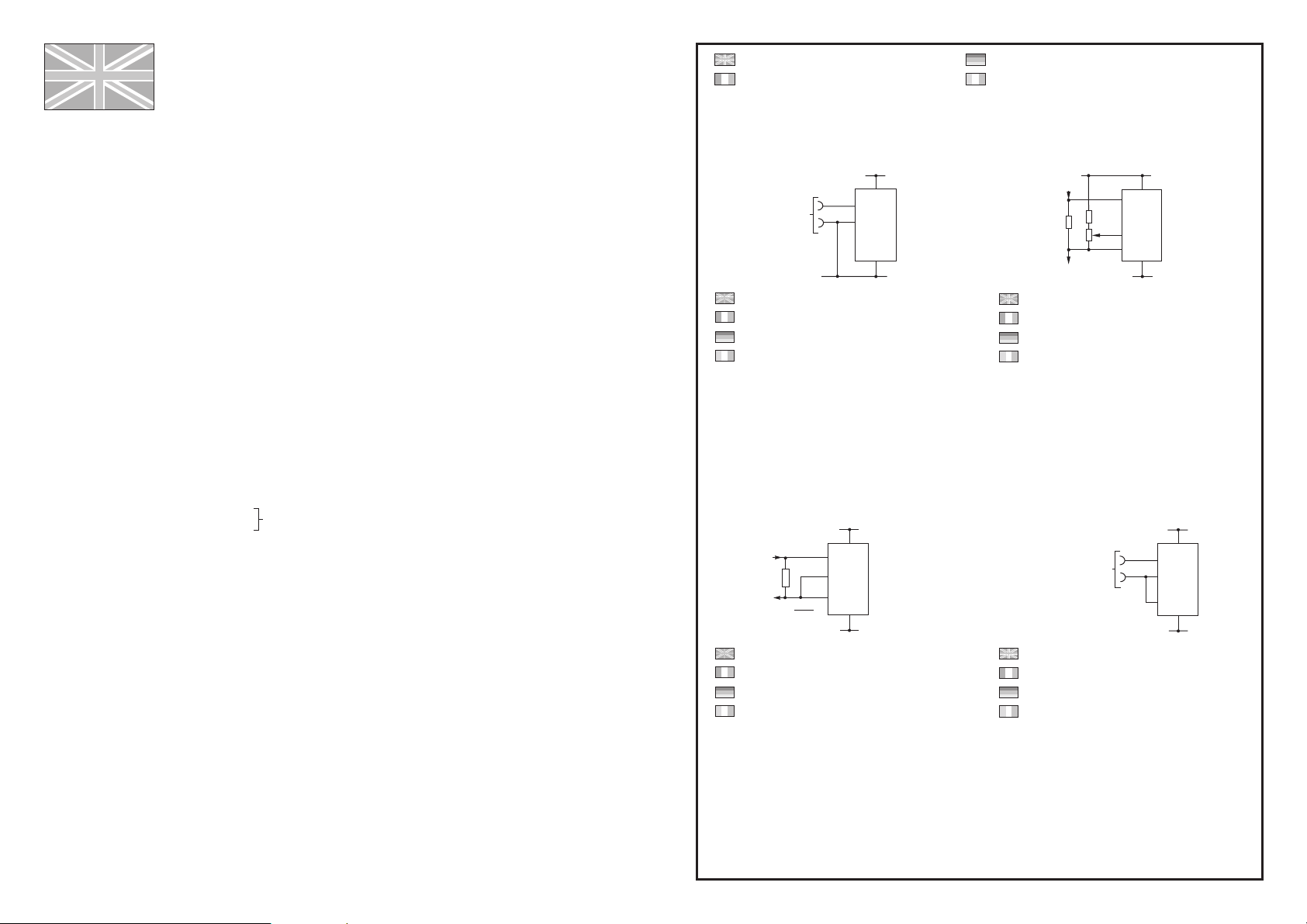
Measuring a single ended input referenced to supply ground.
Mesure d’une entrée à connexion unique référencée à l’alimentation.
Messen eines auf die Versorgung bezogenen massebezogenen Eingangs.
Misurazione di un ingresso con polo in comune rispetto all'alimentazione.
Measuring current.
Mesure decourant.
Strommessung.
Misurazione della corrente.
+
-
+5V
3
IN HI
4
R
R=
IN LO
2
COM
0.2
FSR
I
+5V
1
+5V
3
IN HI
4
IN LO
0V
5
0V
+5V
1
0V
5
0V
IIN
220k
6R2
SET
5k
ZERO
IOUT
Measuring 4-20mA to read 0-999.
Mesure de4-20mA pourlire 0-999.
Messung von4-20mAbeiAnzeige 0 - 999.
Misurazione di 4-20mA per leggere 0-999.
INPUT VOLTAGE
VOLTAGE
D’ALIMENTATION
EINGANGSSPANNUNG
TENSIONE D'INGRESSO
Measuring a floating voltage source of 200mV full scale.
Mesure d’un voltage flottant de 200mV pleine échelle.
Messung einer potentialfreien Spannung mit 200 mV Vollausschlag.
Misurazione di una sorgente di tensione oscillante di 200mV in
grandezza naturale.
3
4
2
+
IN HI
IN LO
COM
-
+5V
0V
+5V
1
5
0V
+5V
1
+5V
3
IN HI
4
IN LO
2
COM
0V
5
0V
2 7
Page 3
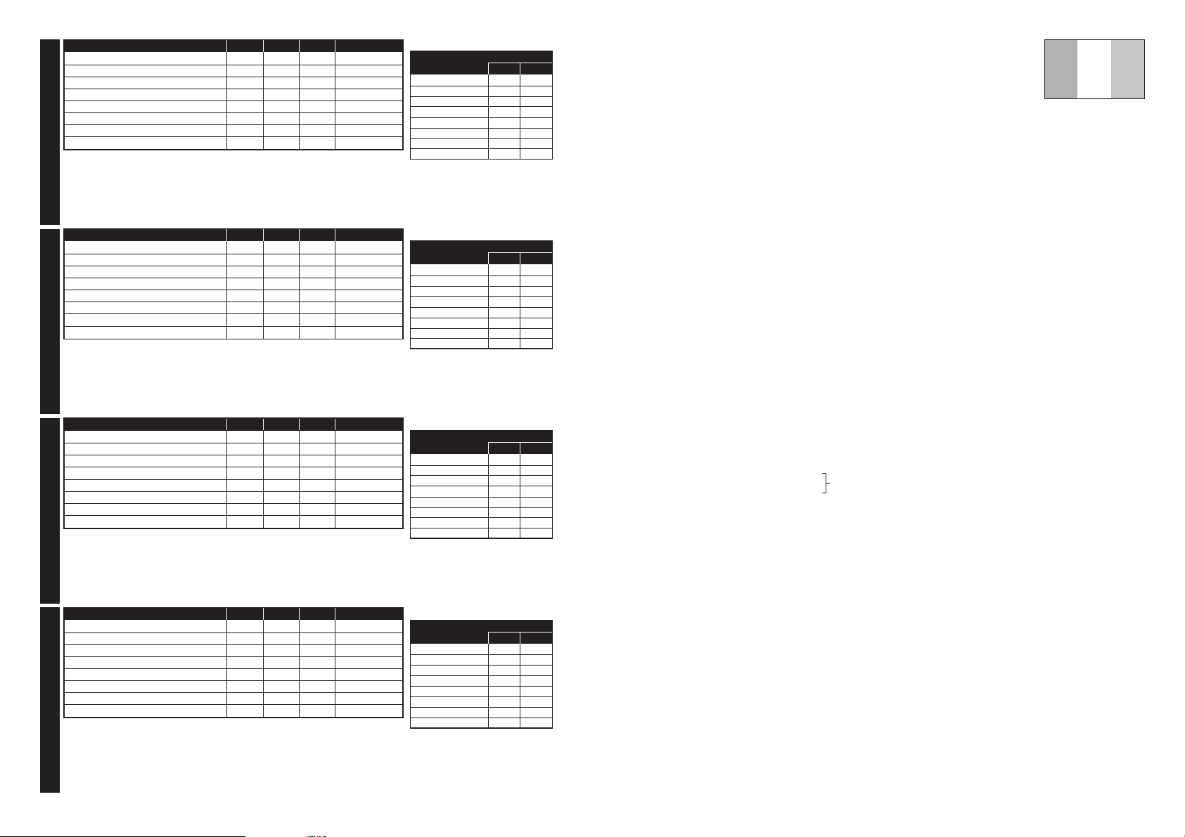
Specification Min. Typ. Max. Unit
Accuracy (overall error) * 0.05 0.1 %(±1 count)
Linearity ±1 count
Sample rate 3 samples/sec
Operating temperature range 0 50 °C
Temperature stability 150 ppm/°C
Supply voltage 4.5 5 5.5 V
Supply current 100 200 mA
Input leakage current (Vin = 0V) 1 10 pA
* To ensure maximum accuracy, re-calibrate periodically.
ENGLISHFRANCAISDEUTSCHITALIANO
**EnsurelinkRaisopeniffittingRa.
SCALING
Required F.S.R.
**
2V 910k 100k
**
20V 1M 10k
**
200V 1M 1k
2kV ** 1M 100R
µ
200 A 0R 1k
2mA 0R 100R
20mA 0R 10R
200mA 0R 1R
Ra Rb
Le DPM 40 est un module LED compact à faible prix qui convient parfaitement aux applications
nécessitant un affichage très lumineux quelles que soient les conditions. Il est doté de LEDs très
performantes et est fourni avec un cadre et un filtre pour donner un affichage d’un excellent
contraste. Sa petite taille et son prixréduit lerendent très intéressant pour les applications OEM à
volume important.
• Taille des Caractères : 11 mm (0,43") • Polarité Automatique
• Point Décimal Programmable • Lecture Pleine Echelle (L.P.E) : 200mV d.c.
• Zéro Automatique • Gèle de l’Affichage
ECHELLE
Deux résistances peuventêtre ajoutéespour changer laL.P.E. (cf. tableau ci dessous).
Notez que l’instrumentdevra êtrere-calibré grâceau potentiomètrede calibrage.
FRANCAIS
Caractéristiques Min. Typ. Max. Unité
Précision (erreur globale)
Linéarité
Taux d’échantillonnage
Températures limites d’utilisation
Stabilité thermique
Voltage d’alimentation
Courant d’alimentation
Courant d’entrée de fuite (Vin = 0V)
Pour obtenir une précision maximum, recalibrez périodiquement.
*
** S’assurer que la liaison Ra est ouverte lorsque Ra est ajoutée.
* 0,05 0,1 %(±1 compte)
±1 compte
3 éch./sec
050°C
150 ppm/°C
4,5 5 5,5 V
100 200 mA
110 pA
Parameter Min. Typisch Max. Einheit
Genauigkeit (Gesamtfehler) %(±1 Zählwert)
Linearität Zählwert
Abtastrate Proben/sek.
Betriebs-temperatur-bereich
Temperatur-stabilität
Versorgungs-spannung
Versorgungsstrom
Kriechstrom am Eingang (Vein = 0V)
Um maximale Genauigkeit zu gewährleisten, periodisch kalibrieren.
*
** Stellen Siesicher,daß dieVerbindung Raoffen ist, wenn Ra eingebaut wird.
* 0,05 0,1
±1
3
050°C
150 ppm/°C
4,5 5 5,5 V
100 200 mA
110 pA
Specifica Min. Tip. Max. Unitá
Precisione (errore complessivo) %(± 1 conteggio)
Linearità conteggio
Frequenza di campionamento campioni /sec.
Gamma temperatura di esercizio
Stabilità temperatura
Tensione di alimentazione
Corrente di alimentazione
Corrente di perdita in entrata (Vin = 0V)
Per garantire la massima precisione, rieffettuare periodicamente la taratura.
*
** In presenzadellaRa,assicurarsicheilcollegamentoRasiaaperto.
* 0,05 0,1
±1
3
050°C
150 ppm/°C
4,5 5 5,5 V
100 200 mA
110 pA
ECHELLE
L.P.E. Désirée
**
2V 910k 100k
**
20V 1M 10k
**
200V 1M 1k
2kV ** 1M 100R
µ
200 A 0R 1k
2mA 0R 100R
20mA 0R 10R
200mA 0R 1R
Ra Rb
MESSBEREICH
Erforderlicher Endausschlag
**
2V 910k 100k
**
20V 1M 10k
**
200V 1M 1k
2kV ** 1M 100R
µ
200 A 0R 1k
2mA 0R 100R
20mA 0R 10R
200mA 0R 1R
Ra Rb
DIMENSIONAMENTO IN SCALA
F.S.R Richiesto
**
2V 910k 100k
**
20V 1M 10k
**
200V 1M 1k
2kV ** 1M 100R
µ
200 A 0R 1k
2mA 0R 100R
20mA 0R 10R
200mA 0R 1R
Ra Rb
SECURITE
Pourrespecter le DirectifBas Voltage(LVD93/68/EEC),les voltagesd’entrées sur les brochesdu module nedoiventpas dépasser
60Vcc. Siles voltages sur les brochesde mesuredépassent 60Vcc, ilfaut monterles résistances d’echelle à l’externedu module.
L’utilisateur doit s’asseur quel’incorporation du DPM dans sonéquipement respecteles sections concernéesde l’IEC1010.
CONNEXIONS
1. DP1 199.9
A. DP1 199.9
B. DP2 19.99
C. DP3 1.999
D. CLOCK/ A connecter à0V pourgeler l’affichage. Laisserouvert pourune utilisation normale.
HOLD
E. DP COM A connecter aux brochesA, B ou C pourafficher lepoint décimal (DP)désiré.
1. +5V Entrée positive de l’alimentation.
2. COM Terre dela section analogique de l’ADC, elle est maintenue à2,8V (nom.)en dessousde +5V. Cette broche
3. IN HI. Entréepositive de mesure. Les tensionsdesentrées analogiques nedoivent pass’approcher à moins
4. IN LO. Entrée négative demesure. de1Vde l’alimentation positiveou àplus de 1,5Ven dessousde 0V.
5. 0V Entrée négativede l’alimentation.
ne doit être utilisée que lorsque l’alimentation est totalement flottante.
connectée différemment dequ’il est décrit pour l’usageconcerné.
Elle ne doit en aucun cas être
6 3
Page 4

DEUTSCH
Dieses kompakte, preisgünstige LED-Modul eignet sich ideal für Anwendungen, bei denen helle
Anzeigen bei allen Bedingungen erforderlich sind. Das DPM 40 enthält hocheffiziente LEDs und
wird mit einem Filter sowie Rahmen geliefert, die einen hohen Kontrast versprechen. Seine
kompakten Abmessungen und günstige Preislage machen dieses Meßgerät zur idealen Wahl für
OEM-Applikationen großer Serien.
Modulo a LED compatto ed economico, particolarmente indicato per le applicazioni in cui è
necessario un display luminoso inogni condizione applicativa. Il DPM 40 è dotato di LED ad alto
rendimento che, unitamente al filtro e alla cornice, formano un display ad elevato contrasto. Le
piccole dimensioni eilcosto contenuto diquesto apparecchio lo rendonoparticolarmente idoneo
alle applicazioni OEMad altivolumi.
ITALIANO
• Ziffernhöhe 11 mm (0,43") • Automatische Polarität
• Programmierbarer Dezimalpunkt • 200 mV= Vollausschlag (F.S.R.)
• Automatische Nullstellung • Digitalhalt
MESSBEREICH
Der Wertfür den Vollausschlag des Meßgeräts kanndurch zwei Widerstände geändert werden –siehe Tabelle.
Beachten Sie, daß das Meßgerät neu kalibriert werden muß, indem das Potentiometer zum Kalibrieren entsprechend
nachgestellt wird.
SICHERHEIT
Damit den Niederspannungsvorschriften(LVD93/68/EEC) entsprochen wird,dürfen die Spannungen,die an die Kontakte des
Moduls angeschlossen werden, nicht über 60 V= liegen. Sollte es erforderlich sein, eine Spannung über 60 V= an die
Meßgeräteeingänge anzulegen, dann muß andas Modul ein externer Spannungsteilerangeschlossen werden. Außerdem muß
der Benutzer dafür sorgen, daß der Einbau des DPM in die Geräte des Anwenders den zutreffenden Abschnitten von BS EN
61010 entspricht (Sicherheitsbestimmungenfür elektrischeGeräte zum Einsatzfür Meßzwecke,Steuerung und imLabor).
STIFTBELEGUNG
A. DP1 199,9
B. DP2 19,99
C. DP3 1,999
D. CLOCK/ Anschluß an 0V, um den angezeigten Meßwert zu halten. Für normalen Betrieb offen lassen.
HOLD
E. DP COM Anschluß an PINs A, B oder C zum Darstellen des gewünschten Dezimalpunktes.
1. +5V Positive Stromversorgung.
2. COM Massefür den Analogbereichdes Wandlers.Dieser PIN wirdaktiv2,8V (Nennwert) unter+5V gehalten und
3. IN HI Positiver Meßdifferentialeingang. Analogeingänge dürfen nicht näher als 1V an die
4. IN LO Negativer Meßdifferentialeingang. positive Versorgung oder 1,5Vunter 0V kommen.
5. 0V Negative Stromversorgung.
wird miteiner fließendenVersorgungeingesetzt. DerAnschluß an andere Klemmen oder Schaltungen muß
unbedingt vermieden werden.
Als Ausnahmen geltendie angegebenen, zutreffenden Betriebsweisen.
• Altezza cifre 12,5 mm (0,5") • Autopolarità
• Punti decimali programmabili • Lettura valori in grandezza naturale
• Autoazzeramento • Mantenimento del display
(F.S.R.) 200 mV c.c.
DIMENSIONAMENTO IN SCALA
Permodificare la lettura deivalori ingrandezza naturale delcontatore, possonoessere utilizzati dueresistori –ved. tavola.
Vasottolineatoche sarà necessario rieseguirela taraturadel contatore regolandoil potenziometrodi taratura.
SICUREZZA
Per essere conformi alla Direttiva sulla bassa tensione (LVD 93/68/EEC), le tensioni in entrata ai pin del modulo non devono
essere superiori a 60V c.c. Nel caso in cui le tensioni alle entrate di misurazione oltrepassino 60V c.c., montare i resistori di
dimensionamento in scala all’esterno del modulo. L’utente deve assicurasi che l’integrazione del DPM nell’apparecchiatura
dell’utente siaconforme alle sezioni pertinenti dellanormativa BSEN 61010 (Requisiti di sicurezzarelativi alleapparecchiature
elettriche per lamisurazione, ilcontrollo e l’usoin laboratorio).
FUNZIONI DEI PIN
A. DP1 199.9
B. DP2 19.99
C. DP3 1.999
D. CLOCK/ Collegare a 0V per mantenere la lettura visualizzata. Lasciare aperto per il funzionamento normale.
HOLD
E. DP COM Collegare al pin A,BoCperselezionare il DP richiesto.
1. +5V Ingresso di alimentazione positiva.
2. COM Messa aterra della sezioneanalogica del convertitore, che vienemantenuta attivamente a2.8 V(nom.) al di
3. IN HI Ingresso di misura positivo. Gli ingressi analogici devono discostarsi di almeno 1 V dall'alimentazione
4. IN LO Ingresso di misura negativo. positiva o risultare inferiori a 1.5 V al di sotto di 0V.
5. 0V Ingresso di alimentazione negativa.
sotto di +5V. Questo pin viene utilizzato esclusivamente quando il modulo viene impiegato con
un'alimentazione completamente fluttuante.
o circuiti, salvoquanto specificato nelle relative modalitàdi funzionamento.
Per nessuna ragionedeve essere collegato adaltri terminali
4 5
 Loading...