

Page 1
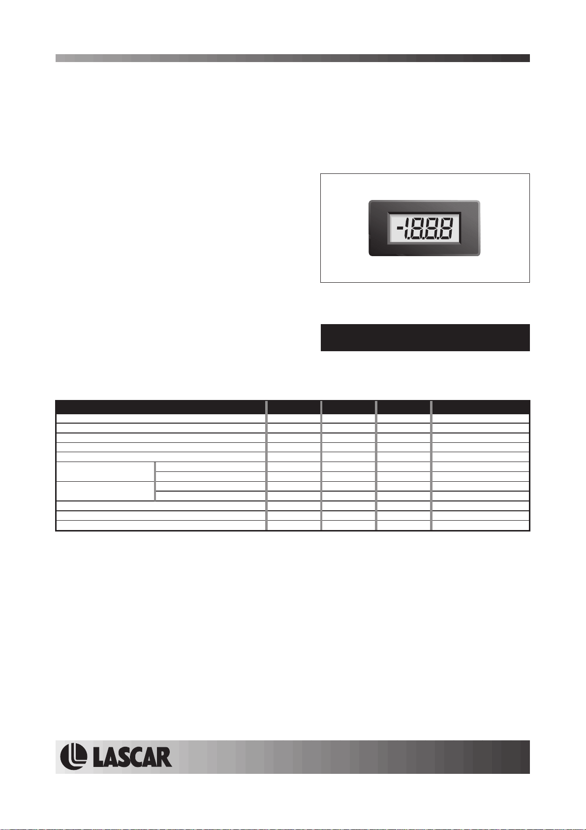
DPM 3AS-BL
3½ Digit Backlit LCD Voltmeter Module
PRODUCT DESCRIPTION
The DPM 3AS-BL features a 200mV d.c. measurement range with auto-zero andauto-polarity. Decimal points are user
selectable.
to its own power supply GND. The design
of the panel meter's housing allows the module to be low cost means it will
The DPM 3AS-BL features a negative rail generator whichenables the meter to measure a signalreferenced
LED backlighting ensures excellent readability under low light conditions.
easily snapped into a panel. The module's
suit high and low volume applications. The DPM 3AS-BL is intended to replace the DPM 3, DPM 3S, DPM 3-BL and
DPM 3S-BL in many applications, usually requiring only minor circuit modifications.
FEATURES
mm (0.43") Digit Height
•11
• 200mV d.c. Full Scale Reading
• 3.0 to 7.5V or 6.0 to 15.0V Operation
•
Auto-zero and Auto-polarity
•
Programmable Decimal Points
•
LED Backlighting
TYPICAL APPLICATIONS
• Precision Instrumentation Systems
• Power Supply Monitoring
• Hand held instruments
• Panel-Mount Indication
• Low Power Voltage Measurement
ORDERING INFORMATION
Stock Number
Standard Meter DPM 3AS-BL
ELECTRICAL SPECIFICATIONS
Specification Min. Typ. Max. Unit
Accuracy (overall error) * 0.1 % (±1 count)
Linearity ±1 count
Sample rate 2.5 samples/sec
Operating temperature range 0 50 °C
Temperature stability 250 ppm/°C
Meter supply voltage V+ to GND configuration 3.0 5.0 7.5 V d.c.
Meter supply current V+ to GND configuration 350 A
Backlight supply voltage 4.75 5.0 *** V d.c.
Backlight supply current @ 5V d.c. 40 60 mA
Input leakage current (Vin = 0V) 1 10 pA
* To ensure maximum accuracy, re-calibrate periodically.
** Operation of the meter beyond the maximum supply voltage rating may cause permanent damage to the meter.
*** An external series resistor is required above 5V, see Applications.
Unless otherwise noted, specifications apply at T =25°C, V =5Vd.c. (f =48kHz) and are tested with the module configured for fully floating
input mode.
V+ to V- configuration 6.0 9.0 15.0** V d.c.
µ
V+ to V- configuration
A supply clock
175 A
µ
SAFETY
To comply with the Low Voltage Directive (LVD 93/68/EEC), input voltages to the module’s pins must not exceed
60Vdc. The user must ensure thatthe incorporationof thepanel meter into the user ’s equipment conforms to the
relevant sections of BS EN 61010 (Safety Requirements for Electrical Equipment for Measuring, Control and
Laboratory Use).
LASCAR ELECTRONICS LTD.
MODULE HOUSE
WHITEPARISH
WILTSHIRE SP5 2SJ
UK
TEL: +44 (1794) 884567
FAX: +44 (1794) 884616
E-mail: [email protected]
LASCAR ELECTRONICS INC.
3750 WEST 26th STREET
ERIE
PA 16506
USA
TEL: +1 (814) 835 0621
FAX: +1 (814) 838 8141
E-mail: [email protected]
www.lascarelectronics.com
LASCAR ELECTRONICS (HK) LIMITED
FLAT C, 5/FL., LUCKY FTY. BLDG.
63-65 HUNG TO ROAD
KWUN TONG KOWLOON
HONG KONG
TEL: +852 2797 3219
FAX: +852 2343 6187
E-mail: [email protected]
Page2of4Page 2 of 4
Page1of4
Page 2
DPM 3AS-BL
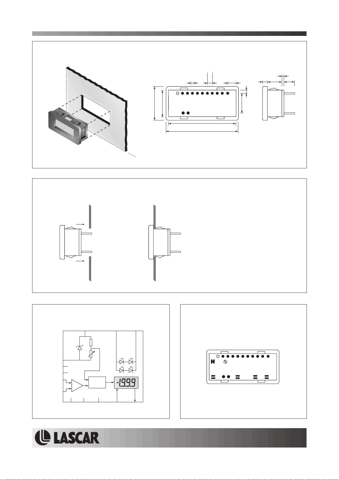
DIMENSIONS
All dimensions in mm (inches)
Panel cut-out: 38.0 x 18.0
PANEL FITTING
(1.50 x 0.71)
20.0 (0.79)
17.5 (0.69)
Panel thickness: 1.0 - 2.5
(0.04 - 0.10)
3½ Digit Backlit LCD Voltmeter Module
2.54 (0.1)
0.50 (0.02)
pin width
37.5 (1.48)
40.0 (1.57)
pin pitch
6.00 (0.24)
ab d
2.00 (0.08)
13.5 (0.53)
c
a. 2.00 (0.08)
b. 6.00 (0.24)
c. 1.60 (0.06)
d. 6.00 (0.24)
Panel
Module
1
FUNCTIONAL BLOCK DIAGRAM
L-L+
8
1
COM
REF HI
REF LO
INHI
INLO
Vref
V+
CAL
+
_
A/D
2
COM
IN HI
(rear view)
1
V-
IN LO
PIN CONFIGURATION
11
LREF
BAT
XDP
TEST
CAL
L-
L+
12 13
V+
GND
REF HI
REF LO
DP1DP2 DP3 BAT
V-TEST
BAT XDPGND
Page2of4Page 2 of 4
www.lascarelectronics.com
Page2of4
Page 3
DPM 3AS-BL
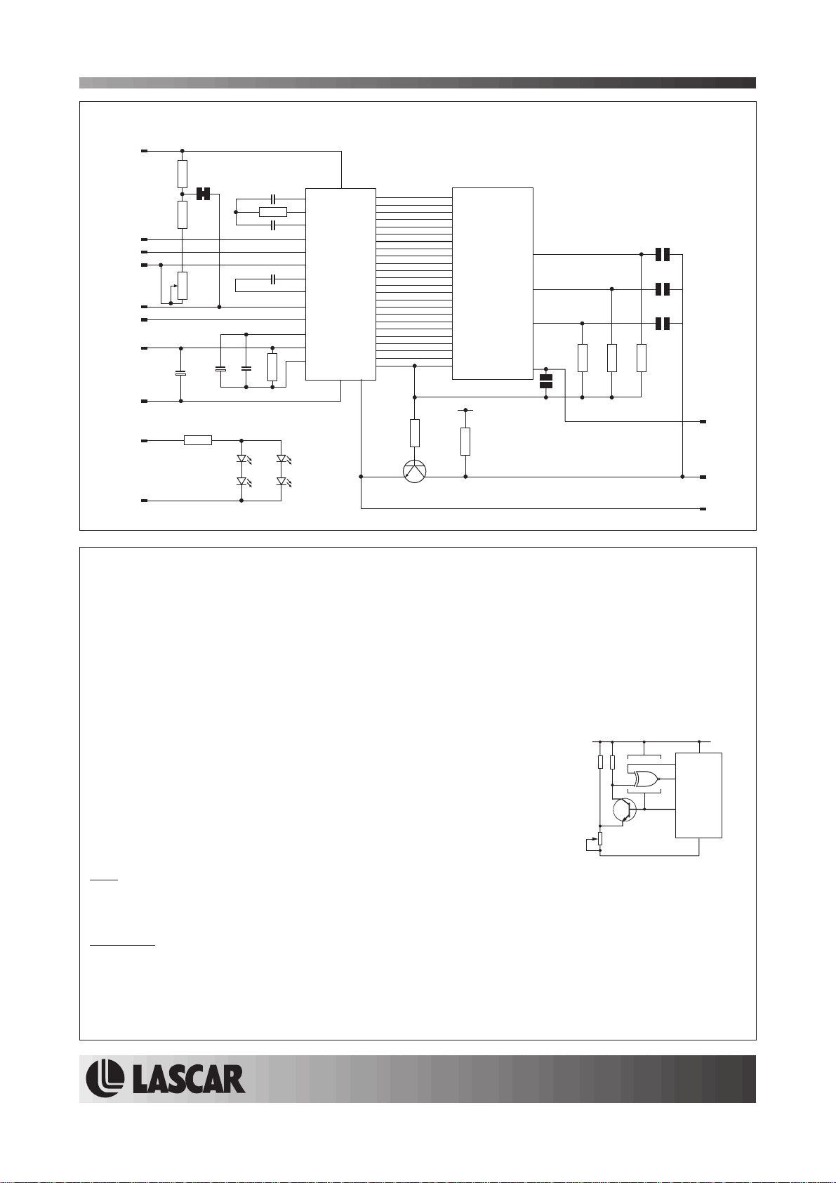
CIRCUIT DIAGRAM
8
V+
R10
100k
INHI
INLO
COM
REF HI
REF LO
GND
LREF
R9
3k
3
2
4
R3
1.5k
6
5
7
1
V-
13
L+
12
L-
R11
22R
C1
47nF
C2
220nF
C4
100nF
R4
C5C7C6
180k
47pF1u51u5
180k
3½ Digit Backlit LCD Voltmeter Module
1
5
V+
27
INT
28
BUF
29
R1
A/Z
31
IN HI
30
IN LO
32
COM
34
CREF+
33
CREF-
36
REF HI
35
REF LO
38
OSC3
39
OSC2
40
OSC1
LED1LED2
IC1
V-
a1
4
b1
3
c1
2
d1
8
e1
6
f1
7
g1
12
a2
11
b2
10
c2
9
d2
14
e2
13
f2
25
g2
23
a3
16
b3
24
c3
15
d3
18
e3
17
f3
22
g3
19
ab
20
POL
21
BP
TEST
37
26
R2
1M
Q1
BCX19
V+
a1
b1
c1
d1
e1
f1
g1
a2
b2
c2
d2
e2
f2
g2
a3
b3
c3
d3
e3
f3
g3
ab
POL
COM
LCD1
R5
100k
DP1
DP2
DP3
LOBAT
BAT
199.9
19.99
1.999
DP1
DP2
DP3
R71MR6
R8
1M
1M
11
BAT
10
XDP
9
TEST
PIN FUNCTIONS
1. V- Negative power supplyto themeter (6.0to 15.0Vmeter power supply applicationsonly).
2. INLO Negativemeasuring input.
3. INHI Positivemeasuring input.
4. COM Ground forthe analogue section ofthe A/D converter.It is activelyheld at3.05V (nom.)below V+ and mustnot be
5. REF LO Negative input forreference voltage.
allowed to sinkexcessive current (>100 A) by,for instance,connecting to ahigher voltage.
6. REF HI Positiveinput for reference voltage.
7. GND 0V power supplyto themeter (3.0 to7.5V meterpower supply applications only).
8. V+ Positivepower supplyto themeter.
9. TEST Connect to V+to testtheLCD. Do notconnectto V+ formore thana few secondsas thismay damagethe LCD.
TEST is heldactively at5V (nom.)below V+and is theground forthe digitalsection ofthe meter.It canbe used to
power external logicup toa maximumof1mA.
10. XDP Inversion of LCD drive voltage.
11. BAT Low Battery annunciator drive pin. See application on the right.
This pin is not fitted as standard.
12. L- Negative power supply to LED backlighting.
13. L+ Positive power supply to LED backlighting.
The backlighting is internally configured for 5V operation.
If a higher voltage is used, then add a series current limiting resistor Rs.
See Applications for calculations of Rs.
Note:
A negative supply is generatedinternally andmirrors thepositive supply. For example: ifV+ is+5V, then theinternally generatedV-
is -5V. When measuring with the input referenced to the same supply rail as that of the panel meter, thenthe limitationson theinput
range are (V- +1.5V) to(V+ -1.5V).
Solder Links:
LREF Normally Closed. Enables theinternal voltagereference circuit. Cut thislink when using anexternal voltage reference.
BAT Normally Open. Disables the LowBattery warningannunciator. Cutthis link and adda low battery detection circuit
to enable theLow Batterywarning annunciator viaPin 11(BAT).
DP1 Normally Open. Close thissolder linkto enabledecimal pointDP1.
DP2 Normally Open. Close thissolder linkto enabledecimal pointDP2.
DP3 Normally Open. Close thissolder linkto enabledecimal pointDP3.
µ
V+
1M
1M
SET
THRESHOLD
BC 237
470k
Check Link BAT is OPEN.
4077
8
V+
10
XDP
11
BAT
9
TEST
V-
1
www.lascarelectronics.com
Page3of4
Page 4
DPM 3AS-BL
3½ Digit Backlit LCD Voltmeter Module
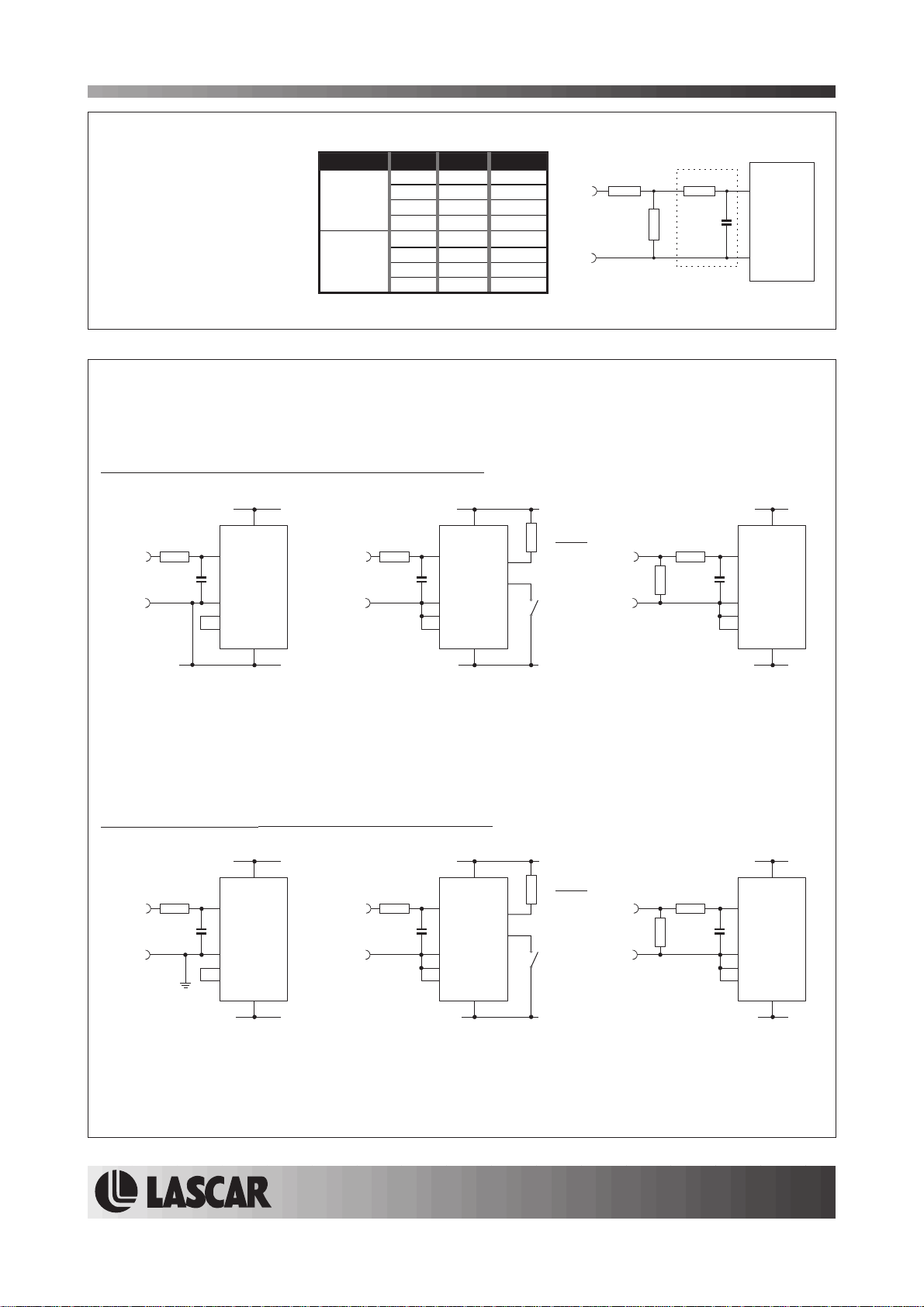
SCALING
Two external resistors Ra
and Rb may be used to
alter the full scale reading
(FSR) of the meter - see
table. The meter will have
to be re-calibrated by
adjusting the calibration
potentiometer on the rear
of themodule.
Voltage
(Vin) 200V 1M 1k
Current
I
( in) 20mA 0R 10R
*Ensure that Ra is rated for high voltage use.
FSR Ra Rb
2V 910k 100k
20V 1M 10k
2000V* 1M 100R
200 A 0R 1k
µ
2mA 0R 100R
200mA 0R 1R
+
Vin or inI
-
Ra 1M
Rb
Input Filter
10nF
INHI
DPM 3AS-BL
INLO
APPLICATIONS
Do not connect more than one meter to the same power supply if the meters cannot use the same signal
ground. Takingany input beyond thepower supplyrails will damage themeter.
5V supply operation (3.0 to 7.5V Meter PowerSupply)
+3.0 to +7.5V
+
±200mV
-
1M
10nF
3
2
4
5
8
V+
INHI
INLO
COM
REF LO
GND
7
Measuring a single ended input
voltage referenced to supply, i.e. the
input voltage and the meter's power
supply share the same 0V rail.
Ensure solder link LREF is closed.
0V
+3.0 to +7.5V
+
±200mV
-
1M
10nF
3
2
4
5
8
V+
INHI
INLO
COM
REF LO
GND
7
Measuring an input voltage referenced to
a floating supply, i.e. the input voltage
and the meter's power supply are isolated
from each other.
Ensure solder link LREF is closed.
9V supply operation (6.0 to 15.0V Meter PowerSupply)
+3.0 to +7.5V
+
±200mV
-
-3.0 to -7.5V
1M
10nF
3
2
4
5
8
V+
INHI
INLO
COM
REF LO
V-
1
+6.0 to +15.0V
+
±200mV
-
1M
10nF
3
2
4
5
8
V+
INHI
INLO
COM
REF LO
V-
1
L+
L+
+3.0 to +7.5V
if V+>5V then
Rs=(V+ - 5V)
13
12
L-
0.04
I+
1M
Rb
10nF
I-
0V
3
2
4
5
INHI
INLO
COM
REF LO
V+
GND
8
7
0V
Measuring a current from a circuit which is
floating with respect to the DPM's supply,
i.e. the current and the meter's power
supply are isolated from each other.
Ensure solder link LREF is closed.
+6.0 to +15.0V
Rs=(V+ - 5V)
13
12
L-
0.04
I+
1M
Rb
10nF
I-
0V
3
2
4
5
INHI
INLO
COM
REF LO
V+
V-
8
1
0V
Measuring a single ended input
voltage referenced to supply, i.e. the
input voltage and the meter's power
supply share the same 0V rail.
Ensure solder link LREF is closed.
Measuring an input voltage referenced to
a floating supply, i.e. the input voltage
and the meter's power supply are isolated
from each other.
Ensure solder link LREF is closed.
Measuring a current from a circuit which is
floating with respect to the DPM's supply,
i.e. the current and the meter's power
supply are isolated from each other.
Ensure solder link LREF is closed.
Specifications liable to change without prior warning DPM 3AS-BL Issue 4 December/2002 M.C. Applies to DPM 3AS-BL/5
Page4of4Page 4 of 4
www.lascarelectronics.com
Page4of4
 Loading...