

Page 1
Prescaler
DN8522S-A
Prescaler IC for CATV
■ Overview
The DN8522S-A is 1.7 GHz prescaler IC for CATV.
It is made up of ECL flip-flop circuit which can be
switched to the dividing ratios of 64, 128 or 256.
■ Features
• Power dissipation: 5 V, 26 mA
• To be switched to the dividing ratios of 64, 128 and 256
• ECL-level output
■ Applications
• Television, VCR
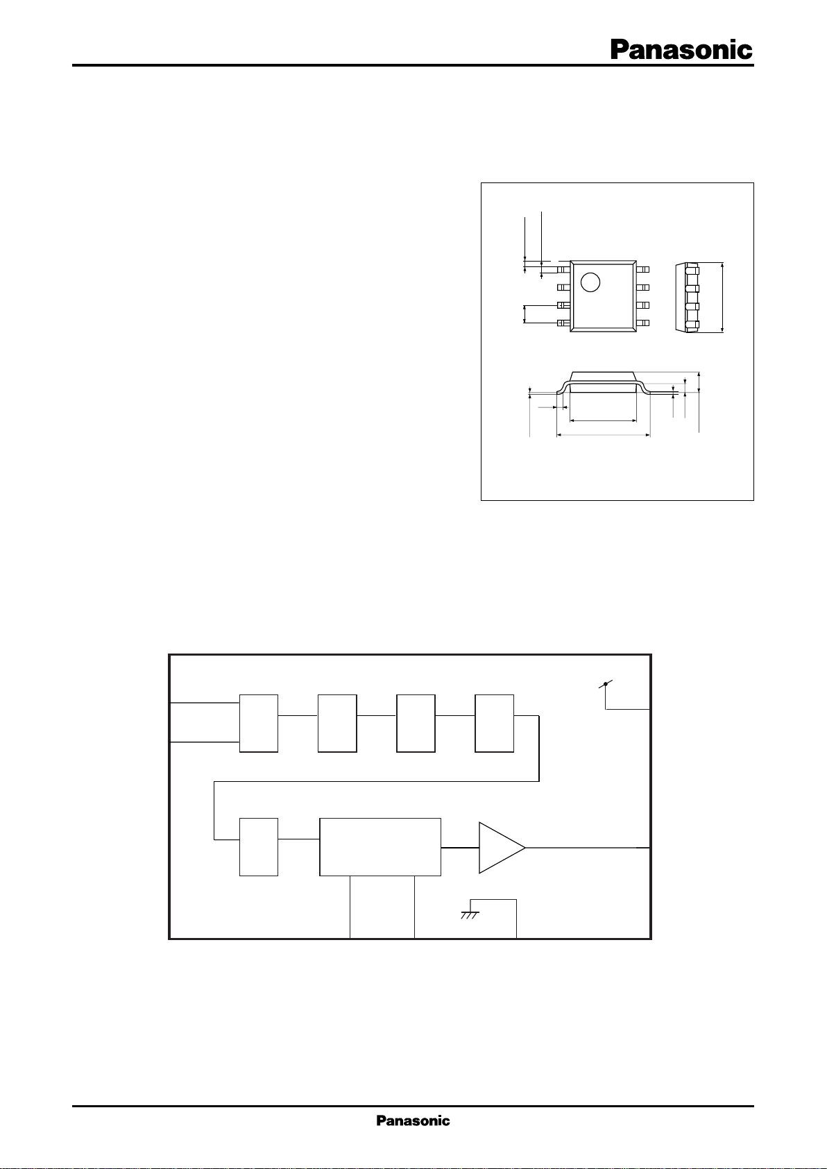
0.6±0.3
0.4±0.25
4
1.27
0.3
0.1±0.1
1
4.2±0.3
6.5±0.3
SOP008-P-0225A
8
5
Unit: mm
0.15
0.65
1.5±0.2
5.0±0.3
■ Block Diagram
1
Input
8
Ref.
1/2
1/2
1/2 1/2 1/2
1/2
1/4
Switch
1/8
3
M1
6
GND
M2
Buff. amp.
5
GND
V
CC
2
V
CC
4
Output
1
Page 2
DN8522S-A Prescaler
■ Pin Descriptions
Pin No. Description
1 Input pin
2 Supply voltage pin
3 Dividing ratio select pin: M1
4 Output pin
5 GND pin
6 Dividing ratio select pin: M2
7 N.C.
8 Bias (Ref.) pin
■ Absolute Maximum Ratings
Parameter Symbol Rating Unit
Supply voltage V
Supply current I
2
Power dissipation
Operating ambient temperature
Storage temperature
Note)
1: Except for the operating ambient temperature and storage temperature, all ratings are for Ta = 25°C.
1. *
2: The power dissipation shown is for the IC package at Ta = 80°C
*
*
1
*
1
*
■ Recommended Operating Range
Parameter Symbol Range Unit
Supply voltage V
■ Electrical Characteristics at Ta = 25°C
Parameter Symbol Conditions Min Typ Max Unit
Supply voltage V
Supply current I
Input frequency f
Input signal level V
CC
VCC = 5 V 26 36 mA
CC
VCC = 5.0 V, VIN = −15 dBm 0.6 1.7 GHz
IN
VCC = 5.0 V, Ta = −20°C to 80°C −15 +3dBm
IN1
fIN = 0.6 GHz to 1.7 GHz
CC
CC
P
D
T
opr
T
stg
CC
6.0 V
40 mA
160 mW
−20 to +80 °C
−55 to +125 °C
4.5 to 5.5 V
4.5 5.0 5.5 V
Output amplitude V
High-level input voltage V
Low-level input voltage V
2
VCC = 5 V, fIN = 1.7 GHz 0.6 1.0 1. 6 V[p-p]
O
VIN = −10 dBm, divided by 64
Dividing ratio select voltage pin 3, 0.7 × V
IH
pin 6 V
Dividing ratio select voltage pin 3, 0.2 × V
IL
CC
pin 6 V
CC
Page 3
Prescaler DN8522S-A
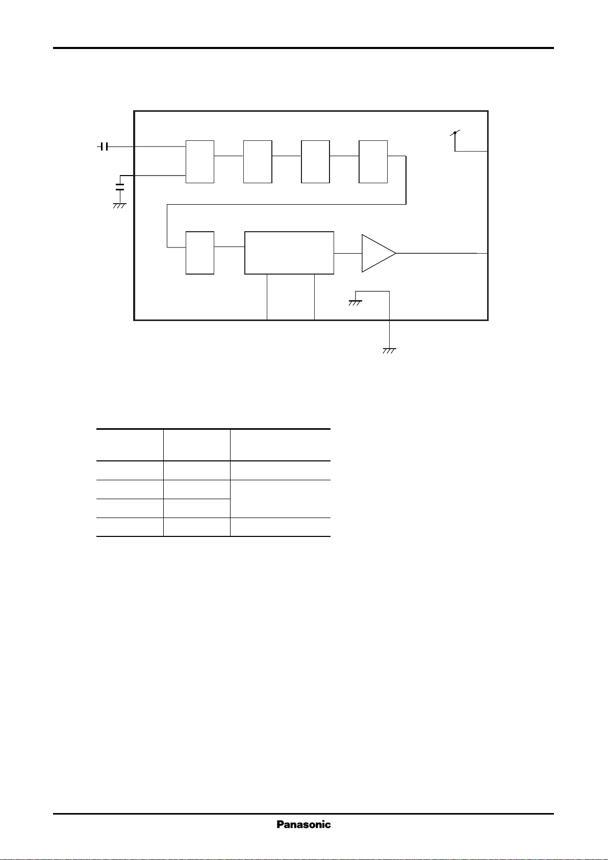
■ Application Circuit Example
Input
0.001 µF
0.001 µF
Ref.
1
8
1/2
1/2
1/2 1/2 1/2
1/2
1/4
Switch
1/8
Buff. amp.
2
4
V
5 V
CC
Output
3
M1
6
M2
5
GND
Dividing ratio select pin: M1/M2 settings and related dividing ratios are as follows: High = VCC , Low = GND
Pin 3 Pin 6
M1 M2
Dividing ratio
Low Low 1/256
Low High 1/128
High Low
High High 1/64
3
 Loading...