

Page 1
®®
DMS-20PC-4/20 Series
New! Bipolar and Positive Reading Models
Subminiature
Order online at www.datel.com
Features
• Industry's fi rst loop-powered meter
with a large, easy-to-read, LED display!
• Self-powered, no external
supply required
• Unipolar, Bipolar and Positive Reading
Models
• Large, 0.37"/9.4mm digits
• Excellent display intensity
• Constant 5V max. total loop drop
• High-quality, 20-turn, span (gain) and
zero (offset) adjustments
• DIP-switch selectable range and
decimal points
• Hundreds of input/readout combinations
• Vibration-resistant package; Reliable
screw-terminal input connections
Actual Size
4-20mA Loop-Powered
3½ Digit, LED ProcessMonitors
The DMS-20PC-4/20 Series are the world's fi rst loop-powered digital panel meters
with a large, easy-to-read, bright red, LED display. All operating power is derived
directly from the loop current itself—no external power supply is required! The large,
0.37"/9.4mm digits exhibit uniform intensity over the entire 4-20mA operating range.
Additionally, the total maximum loop voltage drop is only 5V! Users no longer have to
settle for diffi cult-to-read LCD displays in loop-powered applications.
Both gain (span) and offset (zero) adjustments are performed with on-board, precision, 20-turn potentiometers. All decimal-point and range-change selections are
made on a six-position DIP switch featuring vibration-resistant, gold-plated contacts.
Unlike competitive meters, there are no jumpers or solder gaps to open or close.
Connections to the current loop are made via a reliable, two-position, screw-type
terminal block.
The DMS-20PC-4/20's DIP switch and adjustment potentiometers accommodate
hundreds of different input-current/output-reading combinations. This versatility practically eliminates the need to order more costly, long-lead-time, factory-customized "specials" in applications in which several different-range meters are required. An optional
bezel assembly, featuring screw fasteners and a rubber seal, simplifi es panel mounting
and provides excellent resistance to environmental dust and moisture. All these outstanding features combine to make the DMS-20PC-4/20 Series the perfect meters for
prototype and OEM 4-20mA current-loop instrumentation.
3½ DIGIT A/D
CONVERTER
3
2
R3 R7
GAIN
ZERO
ADJUST
ADJUST
BAND-GAP
REFERENCE
CIRCUIT
+5V –5V
DC/DC
CONVERTER
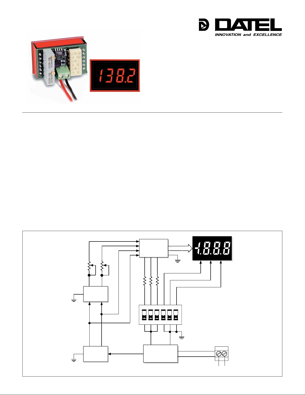
Figure 1. DMS-20PC-4/ 20 Series Simplifi ed Schematic
DATEL, Inc., Mansfi eld, MA 02048 (USA) • Tel: (508)339-3000, (800)233-2765 Fax: (508)339-6356 • E–mail: [email protected] • Internet: www.datel.com
1
1
ON
3
2
CURRENT TO
VOLTAGE
CONVERTER
45
DATA
DP3DP2DP1
DIP SWITCHES
6
TB1
+–
–+
LOOP INPUT
Page 2
DMS-20PC-4/20
3½ DIGIT, LED DISPLAY, 4-20mA LOOP-POWERED METERS
Performance/Functional Specifi cations
Typical at TA = +25°C, unless otherwise noted.
Current Loop Input Min. Typ. Max. Units
Full Scale Input Range ➀ +4 –– +20 mA
Input Impedance ➁ –– 250 –– Ω
Voltage Drop ➁ –– 4.5 5.0 Volts
Overcurrent Protection ➀ –– –– ±40 mA
Performance
Sampling Rate 2.5 readings per second
Accuracy (1 minute warm–up) ±0.05%FS ±1 Count
Temperature Drift (0 to +60°C) –– ±0.15 ±0.3 Cnts/°C
Display
Display Type and Size 3½ digit, red LED, 0.37"/9.4mm
Polarity Indication "–" for negative readings
Overrange Indication "–1_ __ " for negative inputs
"1 _ __ " for positive inputs
Physical/Environmental
Operating Temperature 0 –– +60 °C
Storage Temperature –40 –– +75 °C
Humidity (Non–condensing) 0 –– 95 %
Case Material Polycarbonate
Weight 0.6 ounces (17 grams)
➀ The DMS-20PC-4/20, using any of the DIP-switch settings described above, can
withstand overcurrents, including those resulting from accidental reverse-polarity
connections, up to ±40mA without sustaining any damage.
➁ Because DATEL's DMS-4/20 loop-powered meters employ active circuitry to con-
vert the loop current into a voltage, the meters' effective series impedance varies
in a manner that maintains the loop voltage drop constant over the full 4-to-20mA
current range. Listed impedance specifi cation applies at 20mA.
➂ When looking up DIP-switch settings in the Tables and the desired display readings
can be achieved with either of two different settings, using the higher setting # will
produce less sensitive offset (R3) and span (R7) adjustments. Please keep in mind
that the DMS-20PC standard meter (from which the DMS-20PC-4/20 is derived)
has an accuracy specifi cation of ±2 counts (max.). Thus, it may not always be
possible to obtain the exact desired display reading.
Ordering Information
DMS-20PC-4/20S Unipolar reading, loop-powered LED meter
DMS-20PC-4/20B Bipolar reading, loop-powered LED meter
DMS-20PC-4/20P Positive reading, loop-powered LED meter
DMS-PS4-CM +24V/0.45A AC/DC power supply module
DMS-BZL3 Bezel assembly
DMS-BZL4 Bezel assembly with sealing gasket
DMS-20-CP Panel cutout punch
A panel-mount retaining clip is supplied with each model.
Operating and Setup Instructions
DMS-20PC-4/20S (Unipolar Reading Model)
As shipped, the DMS-20PC-4/20S is factory calibrated to read "000"
for a 4mA input and "1000" for a 20mA input. The following worst-case
procedure assumes the DMS-20PC-4/20S is completely mis-adjusted, i.e.,
both potentiometers and the DIP switches are randomly set. When perform-
ing DIP-switch settings, be sure the DIP switch's small actuators are fi rmly
engaged in their fully-ON or fully-OFF positions.
1. Set R7 (full scale span/gain adjust) and R3 (zero/offset adjust) fully
clockwise, roughly 22 turns, and place SW1-SW6 to OFF.
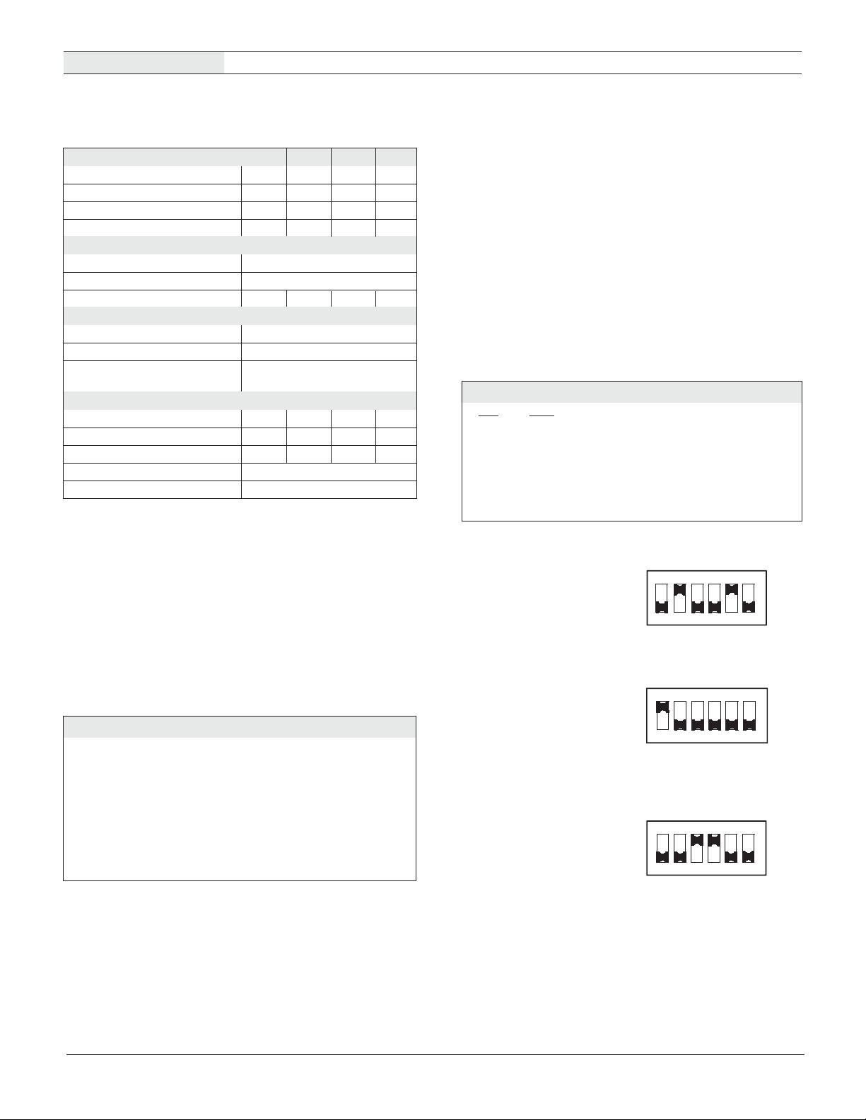
2. Select DIP switch setting #2.
3. Apply a precision 4mA input, with proper polarity, and adjust R3 until
the meter's display reads "000".
4. Apply a precision 20mA input and adjust R7 until the meter's display
reads "1000". Repeat steps 3 and 4 to make sure the adjustments do
not affect one another.
5. Select the appropriate decimal point by setting SW4, SW5 or SW6 to
ON (DP1, DP2 or DP3 respectively).
NOTE: If a display reading other than "000" to "1000" is desired,
refer to DIP–Switch Settings Table 1 for SW1–SW3 settings.
Table 1. DMS-20PC-4/20S (Unipolar Model) DIP-Switch Settings
Display Reading SW1 SW2 SW3
4mA 20mA
1. 000 to 1050-1999 Off Off Off
2. 000 to 650-1350 On Off Off
3. 000 to 450-800 Off On Off
4. 000 to 300-500 Off Off On
5. 000 to 200-300 On On On
Examples (DMS-20PC-4/20S-Unipolar Model)
1. Desired display readings are:
4mA ="0.00"
20mA = "6.00"
Use DIP-switch setting #3 in Table 1 and enable decimal point DP2
via SW5. Apply 4mA and adjust R3 so the display reads "0.00". Apply
20mA and adjust R7 so the display reads "6.00".
2. Desired display readings are:
4mA = "000"
20mA = "800"
Use DIP-switch setting #2 in Table 1. Apply 4mA and adjust R3 so the
display reads "000". Apply 20mA and adjust R7 so the display reads
"800". For these display readings, no decimal points are used. Set
SW4, SW5 and SW6 to OFF.
3. Desired display readings are:
4mA = ".000"
12mA = ".250"
This example is not as straightforward as the previous two. Notice that
12mA is exactly halfway between 4mA and 20mA. If we assume that
the input could go up to 20mA, the display reading would then be:
2 x .250 or ".500". From Table 1 we can now select DIP-switch
setting #4 and enable DP1 via SW4. Apply 4mA and adjust R3 so
the display reads ".000". Apply 12mA and adjust R7 so the display
reads ".250".
ON
2
1
3
ON
123
ON
1234
4
4
56
6
5
56
DATEL, Inc., Mansfi eld, MA 02048 (USA) • Tel: (508)339-3000, (800)233-2765 Fax: (508)339-6356 • E–mail: [email protected] • Internet: www.datel.com
2
Page 3
3½ DIGIT, LED DISPLAY, 4-20mA LOOP-POWERED METERS
DMS-20PC-4/20
DMS–20PC–4/20B (Bipolar Reading Model)
The DMS-20PC-4/20B's zero-offset circuit differs from the unipolar 'S' model
described above in that with the 'B' model, a half-scale 12mA input is
normally set to display "000". Therefore, all of the of the DIP-switch settings
in Table 2 assume a reading of "000" is desired with a 12mA input. Display
readings other than those shown in Table 2 are possible, contact DATEL
for more information.
When confi guring the DMS-20PC-4/20B for the fi rst time, or when selecting
a new range, set both R3 and R7 fully clockwise (roughly 22 turns) to
their minimum offset/minimum-span positions, respectively. Then select the
desired readings from Table 2 and confi gure DIP-switches SW1, SW2, and
SW3 accordingly.
The procedure below illustrates how to calibrate the DMS-20PC-4/20B to its
factory-calibrated readings of "–1000" with a 4mA input and "1000" with a
20mA input. When performing DIP-switch settings, be sure the DIP-switch's
small actuators are fi rmly engaged in their fully-ON or fully-OFF positions.
1. Set both R3 and R7 fully clockwise.
2. Select DIP-switch setting #1 from Table 2.
3. Apply a precision 12mA input and adjust R3 until the meter's display
reads "000".
4. Apply a precision 20mA input and adjust R7 until the meter's display
reads "1000".
5. Apply a precision 4mA input and the display should read "–1000".
Repeat steps 3 and 4 to make sure the two adjustments did not
affect one another.
Table 2. DMS-20PC-4/20B (Bipolar Model) DIP-Switch Settings
Display Reading SW1 SW2 SW3
4mA 12mA 20mA
1. –600 to –1000 000 600 to 1000 Off Off Off
2. –350 to –650 000 350 to 650 On Off Off
3. –250 to –400 000 250 to 400 Off On Off
4. –150 to –250 000 150 to 250 Off Off On
5. –100 to –150 000 100 to 150 On On On
Examples (DMS-20PC-4/20B-Bipolar Model)
1. Desired display readings are:
4mA = "–1.00"
20mA = "1.00"
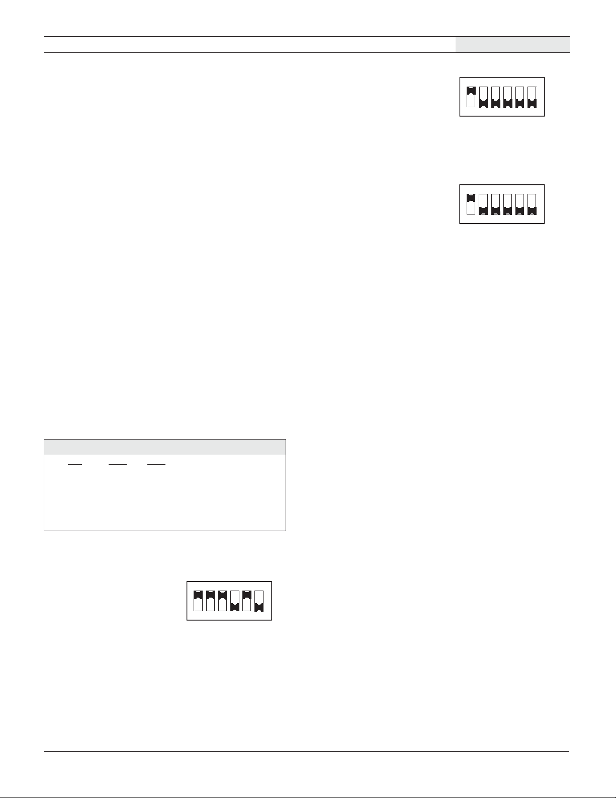
Use DIP-switch setting #5 in Table 2 and enable decimal point DP2 via
SW5. Apply 12mA and adjust R3 so the display reads "0.00". Apply
20mA and adjust R7 so the display reads "1.00". Apply 4mA and verify
that the display reads "–1.00", readjust R3 and R7 if necessary.
ON
1234
56
2. Desired display readings are:
ON
4mA = "–450"
20mA = "450"
123
4
6
5
Use DIP-switch setting #2 in Table 2. Apply 12mA and adjust R3 so
the display reads "000". Apply 20mA and adjust R7 so the display
reads "450". Apply 4mA and verify that the display reads "–450".
Repeat adjustment procedure if necessary. For these display readings,
no decimal points are used. Set SW4, SW5 and SW6 to OFF.
3. Desired display readings are:
ON
4mA = "–650"
20mA = "650"
123
4
6
5
Notice that these readings can be obtained using either DIP-switch
setting #1 or DIP-switch setting #2 in Table 2. In situations like this
where DIP-switch settings overlap, less-sensitive R3/R7 adjustments
can be achieved if the higher DIP-setting # is selected (setting #2 in
this example). Apply 12mA and adjust R3 so the display reads "000".
Apply 20mA and adjust R7 so the display reads "650". Apply 4mA and
verify that the display reads "–650". Repeat adjustment procedure if
necessary.
DMS-20PC-4/20P (Positive Reading Model)
The DMS-20PC-4/20P’s Zero-Offset circuit is optimized to produce positive
readings at both 4mA and 20mA input levels. As shown in Table 3’s fi rst
three columns, a 4mA input can be typically adjusted (using R3, Zero/Offset
Adjust) to display any positive reading between “000” and “800”. The cor-
responding 20mA-input reading is then added to the 4mA offset as a
differential whose magnitude is varied by adjusting R7 (Gain/Span Adjust).
The ‘Differential Range’ column in Table 3 lists the nominal differential
display-readings which can be obtained with R7 at, or very close to, its
full-clockwise, minimum span position. The Differential Range column can
be used as a guide when confi guring the meter for the majority of user
applications. Higher differential ranges are obtainable; however, the use
of higher differential readings results in correspondingly-lower positive read-
ings with 4mA inputs, that is, R3’s clockwise adjustment-range is reduced.
Example #3 below illustrates this concept. Please contact DATEL if there is
any doubt as to whether or not the DMS-20PC-4/20P can be confi gured for
your display readings requirements.
The fi rst step when confi guring the DMS-20PC-4/20P for the fi rst time, or
when selecting a new range, is to set R3 fully counterclockwise and R7
fully clockwise (roughly 22 turns) to their minimum offset/minimum span
positions, respectively.
The next step is to calculate the required display differential-reading; this
is accomplished by subtracting the desired 4mA display reading from the
desired 20mA display reading, disregarding decimal points. Then, using
the calculated differential display-reading to select the appropriate DIP-
switch setting # from Table 3, confi gure DIP-switches SW1, SW2, and SW3
accordingly. Make certain that the DIP-switch’s small actuators are fi rmly
engaged in their fully-ON or fully-OFF positions.
The procedure below describes how to calibrate the meter for an appli-
cation which the DMS-20PC-4/20P easily accommodates: displaying the
output of a 4-20mA transmitter, that is, “04.0” with a 4mA input and “20.0”
with a 20mA input.
DATEL, Inc., Mansfi eld, MA 02048 (USA) • Tel: (508)339-3000, (800)233-2765 Fax: (508)339-6356 • E–mail: [email protected] • Internet: www.datel.com
3
Page 4
DMS-20PC-4/20
T
3½ DIGIT, LED DISPLAY, 4-20mA LOOP-POWERED METERS
1. Set R3 fully counterclockwise (minimum offset position) and R7 fully
clockwise (minimum differential span position), roughly 22 turns.
2. Subtract 040 from 200 to yield a differential value of 160; use this value
to select DIP-switch setting #5 in Table 3. Enable decimal point DP3 by
placing SW6 to the ON position.
3. Set the transmitter’s output to 4.0mA and carefully adjust R3 clockwise
until the meter’s display reads “000”.
4. Set the transmitter’s output to 20.0mA and adjust R7 counterclock-
wise until the meter’s display reads “16.0”.
5. Set the transmitter back to 4.0mA and slowly adjust R3 clockwise until
the display reads “04.0”. Reapply 20.0mA and the display should now
read “20.0”. Repeat steps 3, 4 and 5 to make sure the adjustments did
not affect one another.
Table 3. DMS-20PC-4/20P (Positive Reading Model)
DIP-Switch Settings
Display Reading SW1 SW2 SW3
Differential Range 4mA Input 20mA Input
1. 800-1400 900 1700 Off Off Off
2. 500-800 850 1350 On Off Off
3. 350-500 800 1150 Off On Off
4. 250-350 750 1000 Off Off On
5. 150-250 750 900 On On On
Examples (DMS-20PC-4/20P-Positive Model)
1. Desired display readings are:
4mA = “650”
20mA = “950”
Use DIP-switch setting #4 in Table 3 since subtracting 650 from 950
yields a differential value of 300. Apply 4mA and adjust R3 until the
display reads “000”. Apply 20mA and adjust R7 until the display reads
“300” (the differential value previously calculated). Apply 4mA and
adjust R3 until the display reads “650”. Apply 20mA and verify that the
display reads “950”.
2. Desired display readings are:
4mA = “4.00”
20mA = “19.99”
This example illustrates the DMS-20PC-4/20P’s capability to display
higher differential readings than those indicated in Table 3. This exam-
ple also illustrates how the DMS-20PC-4/20P can be used to display
the output levels of a 4-20mA loop transmitter with higher precision
(0.01mA versus 0.1mA) than described above.
Subtracting 400 from 1999 yields a differential of 1599, a value not
listed in Table 3. However, use DIP-switch setting #1 in Table 3 since
this setting has the highest overall offset/span adjustment capabilities.
Enable DP2 via SW5 then apply 4mA and adjust R3 so the display
reads “0.00”. Apply 20mA and adjust R7 so the display reads “15.99”.
ON
1234
ON
2
1
3
4
56
56
Apply 4mA and adjust R3 until the display reads “4.00”. Apply 20mA
Table 4. Decimal Point Settings
SW4 SW5 SW6
DP1 DP2 DP3
and check to see that the display reads “19.99” or just overranges
(“1—“). Repeat adjustment procedure if necessary.
PROGRAMMABLE
LOGIC CONTROLLER
TRANSMITTER &
SIGNAL CONDITIONER
+
+
RANSDUCER
INPUT
85-264Vac
+24Vdc
SUPPLY
+24V
+
4-20mA
4-20mA
➀
DMS-20PC-4/20
–
(TB1-1)
+
+
Vsig
(TB1-2)
––
➀ Shown for illustrative purposes only, may not be present in all applications
–
A/D
GAIN
R7
R3
ZERO
–
DMS-PS4-CM
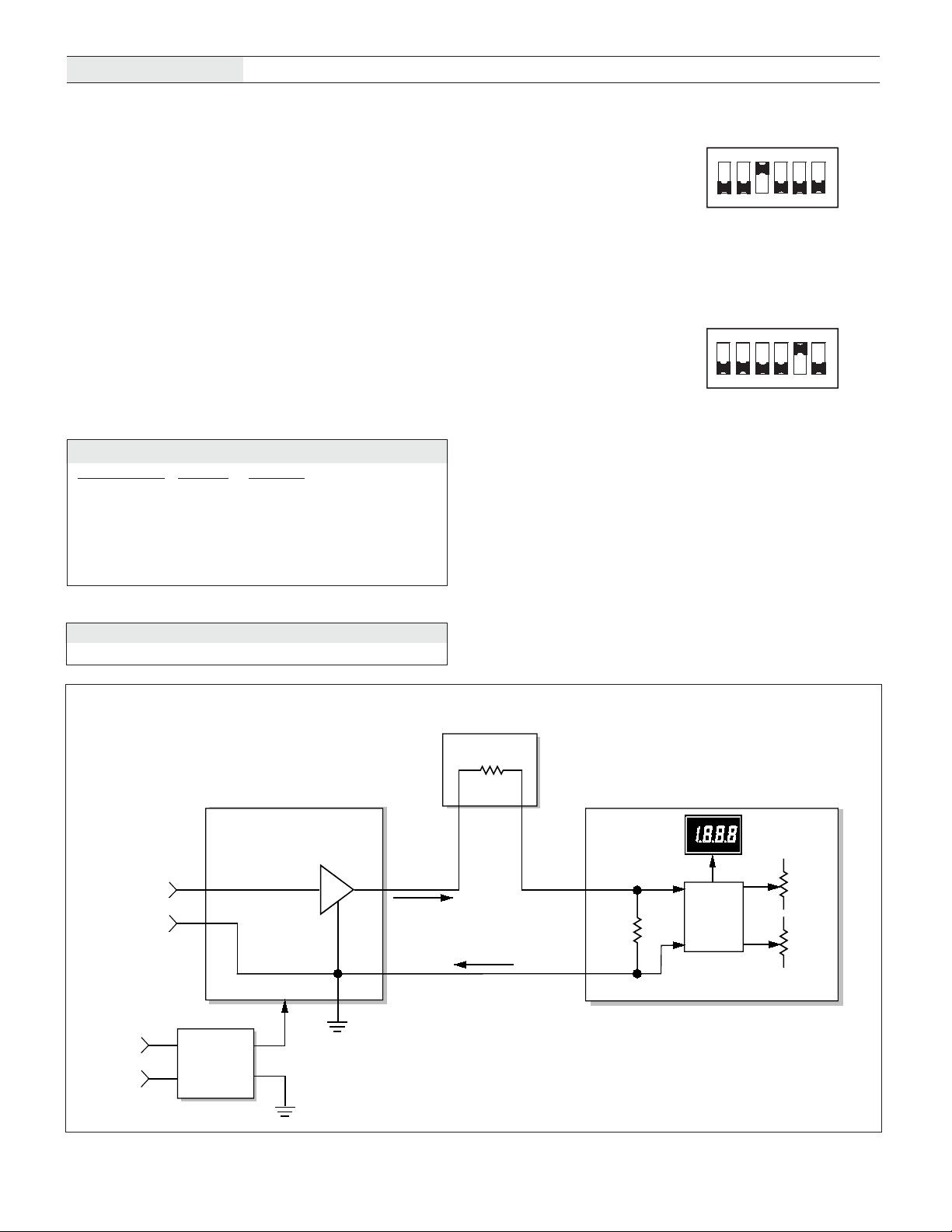
Figure 2. Typical DMS-20PC-4/20 Connection Diagram
DATEL, Inc., Mansfi eld, MA 02048 (USA) • Tel: (508)339-3000, (800)233-2765 Fax: (508)339-6356 • E–mail: [email protected] • Internet: www.datel.com
4
Page 5
DMS-20PC-4/20
Mechanical Specifi cations
3½ DIGIT, LED DISPLAY, 4-20mA LOOP-POWERED METERS
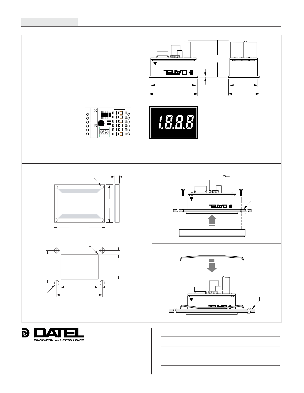
MECHANICAL DIMENSIONS: Inches (mm)
TOLERANCES: 2 PL DEC ±0.02 (±0.51)
3 PL DEC ±0.010 (±0.254)
WIRE SIZE: 18 to 26 AWG
(Solid or stranded)
STRIPPING LENGTH: 0.20" (5.08mm)
Zero/Offset
Adjust
12
R3
+–
R7
12
Adjust
+ -
Loop
Input
Gain/Span
Back View
FRONT VIEW
DMS-BZL4 BEZEL
#2-56 INSERT
0.156 (3.96) DEEP
0.187
(4.75)
DIP
Switches
1
1
2
2
3
3
4
4
5
5
6
6
0.95
MADE IN USA
1.30
(33.0)
1.38
(35.1)
ON
1
DP2
DP1
(SW5)
(SW4)
DP3
(SW6)
DMS-20PC-4/20S
0.040
(1.02)
(24.1)
0.80
(20.3)
0.88
(22.4)
Front View
BEZEL INSTALLATION
1.280
(32.51)
1.826 (46.38)
®®
BEZEL
PANEL
RECOMMENDED DRILL AND PANEL CUTOUT DIMENSIONS
INTERNAL CORNER RADII:
0.032 (0.81) MAX.
0.116 (2.95)
RETAINING CLIP INSTALLATION
1.07
(27.18)
1.336 (33.93)
1.626 (41.30)
0.093 (2.362) DIAMETER (4 REQUIRED)
ONLY WHEN USING OPTIONAL BEZEL ASSEMBLY
®®
0.838
(21.29)
0.145 (3.68)
PANEL
®®
DATEL (UK) LTD. Tadley, England Tel: (01256)-880444
Internet: www.datel-europe.com E-mail: [email protected]
DATEL S.A.R.L. Montigny Le Bretonneux, France Tel: 01-34-60-01-01
Internet: www.datel-europe.com E-mail: [email protected]
DATEL, Inc. 11 Cabot Boulevard, Mansfield, MA 02048-1151
Tel: (508) 339-3000 (800) 233-2765 Fax: (508) 339-6356
Internet: www.datel.com E-mail: [email protected]
DATEL GmbH München, Germany Tel: 89-544334-0
Internet: www.datel-europe.com E-mail: [email protected]
DATEL KK Tokyo, Japan Tel: 3-3779-1031, Osaka Tel: 6-6354-2025
Internet: www.datel-co.jp E-mail: [email protected], [email protected]
ISO 9001:2000 REGISTERED
DATEL makes no representation that the use of its products in the circuits described herein, or the use of other technical information contained herein, will not infringe upon existing or future patent rights. The descriptions contained herein do
not imply the granting of licenses to make, use, or sell equipment constructed in accordance therewith. Specifi cations are subject to change without notice. The DATEL logo is a registered DATEL, Inc. trademark.
DS-0353D 05/03
DATEL China Shanghai, China Tel: 011-86-51317131
E-mail: [email protected]
Page 6
DMS-30PC-4/20S
3½ DIGIT, 4-20mA INPUT, LED DISPLAY METERS
Performance/Functional Specifications
Typical at TA = +25°C, unless otherwise noted.
Current Loop Input Min. Typ. Max. Units
Full Scale Input Range +3.5 -- +22 mA
Input Impedance -- 100 --
Ω
Voltage Drop -- -- 2.0 Volts
Overcurrent Protection -- -- ±40 mA
Performance
Sampling Rate 2.5 readings per second
Accuracy (1 minute warm-up) ±0.05%FS ±1 Count
Temperature Drift (0 to +60°C) -- ±0.15 ±0.3 Cnts/°C
Power Supply Requirements
➀➀
➀
➀➀
DMS-30PC-4/20S-5RS +4.75 to +5.25Vdc at 225mA max.
DMS-30PC-4/20S-5GS +4.75 to +5.25Vdc at 225mA max.
DMS-30PC-4/20S-5RH +4.75 to +5.25Vdc at 225mA max.
DMS-30PC-4/20S-5RL +4.75 to +5.25Vdc at 20mA max.
DMS-30PC-4/20S-24RL +7.5 to +32Vdc at 30mA max.
DMS-30PC-4/20S-24XX-I Models +21.6 to +26.4Vdc at 60mA max.
Display
Display Type and Size 3½ digit LED, 0.56"/14.2mm high
Polarity Indication "–" for negative readings
Overrange Indication "–1_ _ _" for negative inputs
"1_ _ _" for positive inputs
Physical/Environmental
Operating Temperature 0 -- +60 °C
Storage Temperature – 40 -- +75 °C
Humidity (Non-condensing) 0 -- 95 %
Case Material Polycarbonate
Weight 1 ounce (28 grams)
DIP-Switch Settings Table ➁
Display Reading SW1 SW2 SW3 SW4
1. 000 to 100-300 On On On Off
2. 000 to 400-600 Off On Off Off
3. 000 to 700-1999 On Off Off Off
4. ±100 On On On Off
5. ±200 to ±300 On On Off Off
6. ±400 to ±600 On Off Off Off
7. ±700 to ±1900 Off Off Off On
➀
Input Grounding: Except for the "-I"suffix models which feature isolated
current loop inputs, all other DMS-30PC-4/20S meters are supplied with
their 4-20mA negative-input terminals (TB1-2, "-") internally connected to
their power supply ground terminal (TB2-2, “-V”). This single-ended input
configuration is compatible with most grounded-referenced 4-20mA
transmitters.
Applications in which the DMS-30PC-4/20S and its associated 4-20mA
transmitter are connected to a common ground and the transmitter drives two or
more loads (for example, the meter in series with a PLC) must have the meter
connected as the first device in the current loop, that is, closest to the system
ground (see Figure 2). If this is not possible and/or the meter must be connected
in the middle of the current loop, then'-I' suffix models must be used to provide
the required isolation between the meter’s current loop input and the power
supply ground ("-V"). See Figures 2, 3, 4, and 5 for typical loop connections.
➁
When looking up DIP-switch settings in the Table and the desired display
readings happen to fall between two switch settings, try performing the
adjustments with both settings to determine which one offers the better
settability. Please keep in mind that the DMS-30PC meter (from which
the DMS-30PC-4/20S is derived) has an accuracy specification of ±2
counts (max.). Thus, it may not always be possible to obtain the exact
desired display reading.
Order on-line at www.datel.com
Ordering Information
DMS-30PC-4/20S-5RS +5V supply, standard-intensity red LED's
DMS-30PC-4/20S-5GS +5V supply, standard-intensity green LED's
DMS-30PC-4/20S-5RL +5V supply, low-power red LED's
DMS-30PC-4/20S-5RH +5V supply, high-intensity red LED's
DMS-30PC-4/20S-24RL +7.5V to +32V supply, low-power red LED's
DMS-30PC-4/20S-24RS-I+24V isolated supply, standard-intensity
DMS-30PC-4/20S-24RH-I+24V isolated supply, high-intensity red LED’s
DMS-30PC-4/20S-24BS-I+24V isolated supply, high-intensity blue LED’s
DMS-30PC-4/20S-24GS-I+24V isolated supply, standard-intensity
DMS-PS4-CM +24V/0.45A AC/DC power supply module
DMS-PS7-CM +24V/0.7A AC/DC power supply module
DMS-BZL1 Panel-mount bezel assembly
DMS-BZL2 Panel-mount bezel with sealing gasket
DMS-30-CP Panel cutout punch
A panel-mount retaining clip is supplied with each model.
Operating and Setup Instructions
As shipped, the DMS-30PC-4/20S is factory calibrated to read "000"
for a 4mA input and "1999" for a 20mA input. The following worst-case
procedure assumes the DMS-30PC-4/20S is completely mis-adjusted, i.e.,
both potentiometers and the DIP switches are randomly set.
1. Set R7 (gain/span adjust) and R3 (zero/offset adjust) fully clockwise,
roughly 20 turns, and place SW1-SW8 to OFF (down position).
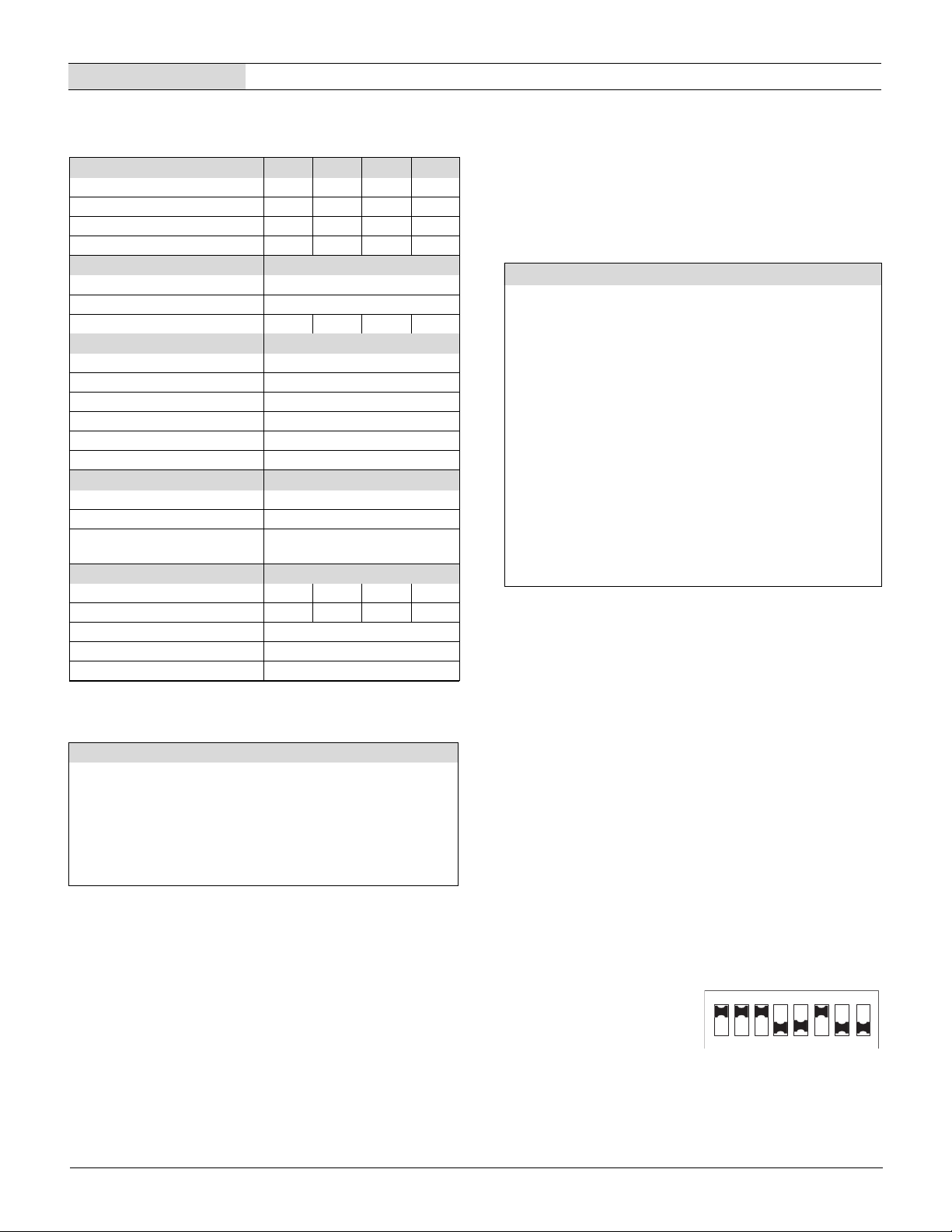
2. Set SW1 to ON (up position). See DIP switch setting #3.
3. Apply a precision 4mA input, with proper polarity, and adjust R3 until
the meter's display reads "000".
4. Apply a precision 20mA and adjust R7 until the display reads "1999".
Repeat 3 and 4 to make sure adjustments do not affect one another.
5. If desired, select the appropriate decimal point by setting either SW5,
SW6 or SW7 to ON (DP1, DP2 or DP3 respectively).
NOTE: If a display reading other than "000" to "1999" is desired,
refer to the DIP-Switch Settings Table for SW1-SW4 settings.
Examples
1. Desired display readings are:
4mA ="0.00"
20mA = "2.00"
Use DIP-switch setting #1 and enable decimal point DP2 via SW6.
Apply 4mA and adjust R3 so the display reads "0.00". Apply 20mA and
adjust R7 so the display reads "2.00".
red LED’s
green LED’s
O N
O N
4
2
1
3
1
2
1
4
3
7 8
6
5
7
8
6
5
DATEL, Inc., Mansfield, MA 02048 (USA) • Tel: (508)339-3000, (800)233-2765 Fax: (508)339-6356 • E-mail: [email protected] • Internet: www.datel.com
2
 Loading...