

Datasheet DM74LS670N, DM74LS670MX, DM74LS670M, DM74LS670CW Datasheet (Fairchild Semiconductor)
Page 1
© 2000 Fairchild Semiconductor Corporation DS006436 www.fairchildsemi.com
August 1986
Revised March 2000
DM74LS670 3-STATE 4-by-4 Register File
DM74LS670
3-STATE 4-by-4 Register File
General Description
These register files are organized as 4 words of 4 bits
each, and separate on-chip decoding is provided for
addressing the four word locations to either write-in or
retrieve data. This permits writing into one location, and
reading from another word location, simultaneously.
Four data inputs are available to supply the word to be
stored. Location of the word is determined by the write
select inputs A and B, in conjunction with a write-enable
signal. Data applied at the inputs should be in its true form.
That is, if a high level signal is desired from the output, a
high level is applied at the data in put for tha t particular bit
location. The latch inputs a re arranged so that new data
will be accepted only if both internal addre ss gate inputs
are HIGH. When this condition exists, data at the D input is
transferred to the latch output. When the write-enable
input, G
W
, is HIGH, the data inputs are inhibited and their
levels can cause no change in the information stored in the
internal latches. W h en the r ead -enable input, G
R
, is HIGH,
the data outputs are inhibited an d go into the high impedance state.
The individual address lines permit direct acquisition of
data stored in any four of the latches. Four individual
decoding gates are used to co mple te th e ad dre ss for rea ding a word. When the read addre ss is ma de in con juncti on
with the read-enable sig nal, the word appears at the four
outputs.
This arrangement—data entry addressing separate from
data read addressin g and individual sense line — elimi-
nates recovery times, permits simultaneous reading and
writing, and is limited in speed only by the write time (27 ns
typical) and the read time (24 ns typica l). The register fi le
has a non-volatile readout in that data is not lost when
addressed.
All inputs (except read enable and w rite enable) are b uffered to lower th e driv e require ments to one no rmal Series
DM74LS load, and inpu t clamping diod es minimi ze switching transients to simplify system design. High spee d, double ended AND-OR-INVERT gat es are employed for the
read-address function and have high sink current, 3-STATE
outputs. Up to 128 of th ese o utp uts may be wire-AND connected for increa sing the capacity up to 5 12 words. Any
number of these regi sters may be parallel ed to provide nbit word length.
Features
■ For use as:
Scratch pad memory
Buffer storage between processors
Bit storage in fast multiplication designs
■ Separate read/write addressing permits simultaneous
reading and writing
■ Organized as 4 words of 4 bits
■ Expandable to 512 words of n-bits
■ 3-STATE versions of DM74LS170
■ Fast access times 20 ns typ
Ordering Code:
Devices also availab le in Tape and Reel. Specify by appending th e s uffix let t er “X” to the ordering code.
Order Number Package Number Package Description
DM74LS670M M16A 16-Lead Small Outline Integrated Circuit (SOIC), JEDEC MS-0 12, 0.150 Narrow
DM74LS670N N16E 16-Lead Plastic Dual-In-Line Package (PDIP), JEDEC MS-001, 0.300 Wide
Page 2
www.fairchildsemi.com 2
DM74LS670
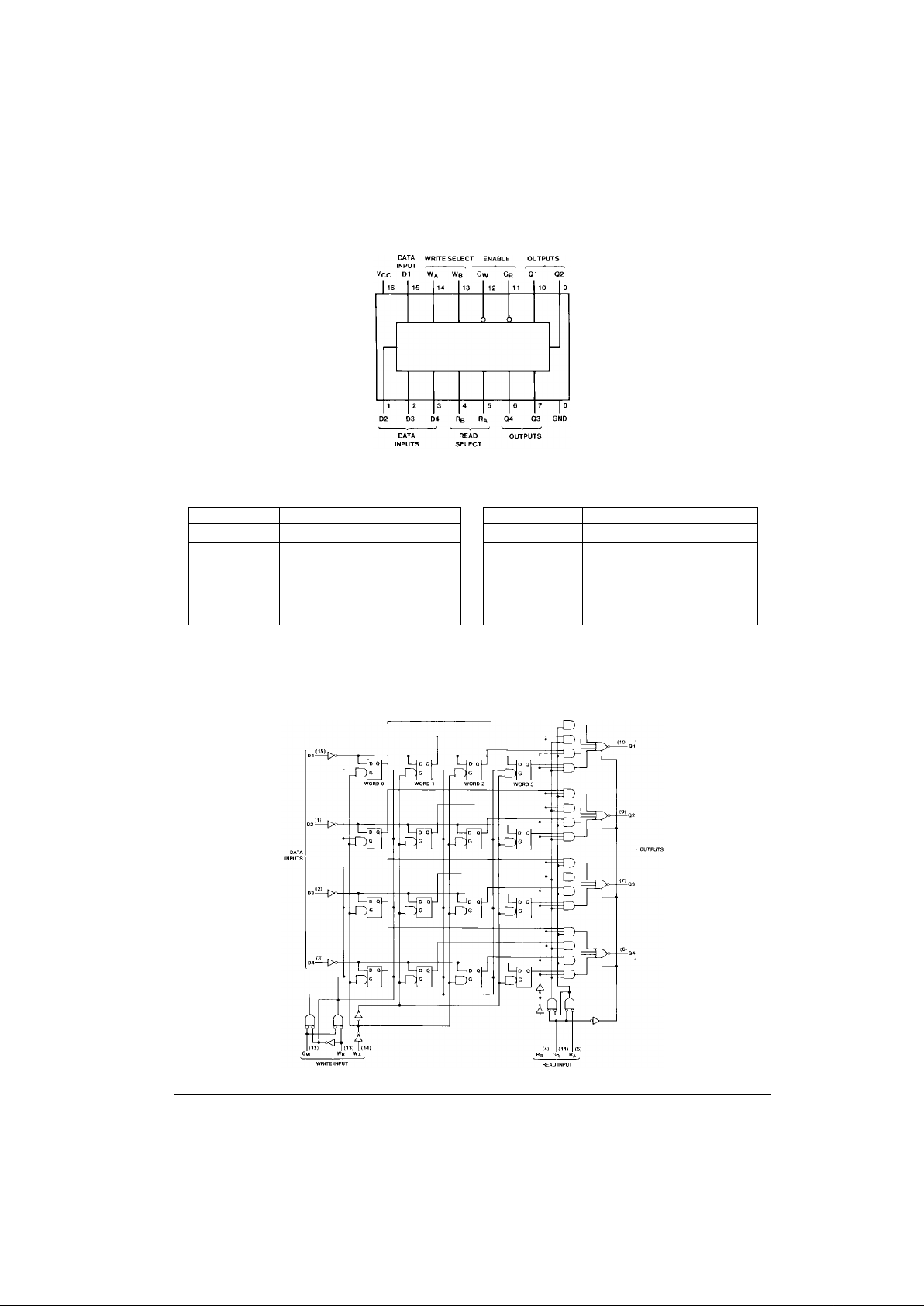
Connection Diagram
Function Tables
Write Table
(Note 1)(Note 2) Read Table (Note 3)
H = HIGH Level L = LOW Level X = Don’t Care Z = High Impedance (OFF)
Note 1: (Q = D) = The four selected inte rnal flip-flop outputs will assume the states app lied to the four external dat a inputs.
Note 2: Q
0
= The level of Q befo re t he indicated input cond iti ons were established .
Note 3: WOB1 = The first bit of word 0, etc.
Logic Diagram
Write Inputs Word
W
BWAGW
0123
LLLQ = DQ
0
Q
0
Q
0
LHL Q0Q = DQ0Q
0
HLL Q0Q0Q = DQ
0
HHL Q0Q
0
Q0Q = D
XXH Q
0
Q
0
Q
0
Q
0
Read Inputs Outputs
R
BRAGR
Q1 Q2 Q3 Q4
L L L WOB1 WOB2 WOB3 WOB4
L H L W1B1 W1B2 W1B3 W1B4
H L L W2B1 W2B2 W2B3 W2B4
H H L W3B1 W3B2 W3B3 W3B4
XXHZZZZ
Page 3
3 www.fairchildsemi.com
DM74LS670
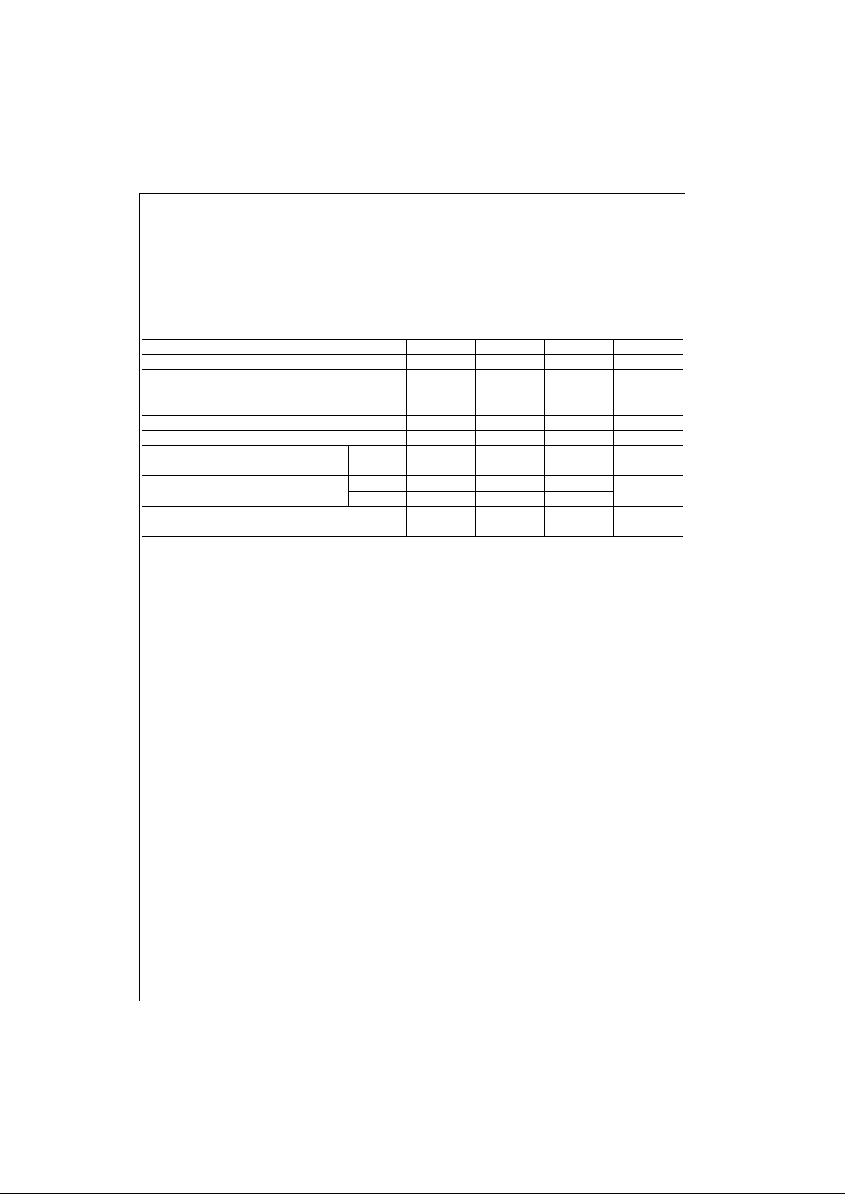
Absolute Maximum Ratings(Note 4)
Note 4: The “Absolute M aximu m R atin gs” are t hose valu es b eyo nd w hich
the safety of the device cannot be guaranteed. The device should not be
operated at these limits. The parametric values defined in the Electrical
Characteristics tables are not guaranteed at the absolute maximum ratings.
The “Recommend ed O peratin g Cond itions” t able w ill defin e the condition s
for actual device operation.
Recommended Operating Conditions
Note 5: TA = 25°C and VCC = 5V.
Note 6: Times are with respect t o the Write-Enable i nput. Write-Select time will protect the data written into the previous address. If protection of data in the
previous address, t
SETUP
(WA, WB) can be ignored. As any address selection sustained for the fin al 30 ns of the Write-Ena ble pulse and during tH (WA, WB)
will result in data being writ ten into that loca tion. D epen din g on the durat ion of the inpu t cond itions , on e or a num ber of previous addresses may have been
written into.
Note 7: Latch time is the time allowed for the internal output of the latch to assume the state of new data. This is important only when attempting to read from
a location immediately after that location h as rec eived new data.
Supply Voltage 7V
Input Voltage 7V
Operating Free Air Temperature Range 0°C to +70°C
Storage Temperature Range −65°C to +150°C
Symbol Parameter Min Nom Max Units
V
CC
Supply Voltage 4.75 5 5.25 V
V
IH
HIGH Level Input Voltage 2 V
V
IL
LOW Level Input Voltage 0.8 V
I
OH
HIGH Level Output Current −2.6 mA
I
OL
LOW Level Output Current 24 mA
t
W
Write Enable Pulse Width (Note 5) 25 ns
t
SU
Setup Time Data 10
ns
(Note 5)(Note 6) W
A
, W
B
15
t
H
Hold Time Data 15
ns
(Note 5)(Note 6) W
A
, W
B
5
t
LATCH
Latch T ime for New Data (Note 5)(Note 7) 25 ns
T
A
Free Air Operating Temperature 0 70 °C
Page 4

www.fairchildsemi.com 4
DM74LS670
Electrical Characteristics
over recommended operating free air temperature range (unless otherwise noted)
Note 8: All typicals are at VCC = 5V, TA = 25°C.
Note 9: Not more than one output should be shorted at a time, and the duration should not exceed one second.
Note 10: I
CC
is measured with 4.5 V applied to all DATA inputs and both ENABLE in puts, all ADDRESS inputs are grounded and all outputs are OPEN.
Switching Characteristics
at VCC = 5V and TA = 25°C
Note 11: CL = 5 pF.
Symbol Parameter Conditions Min
Typ
Max Units
(Note 8)
V
I
Input Clamp Voltage VCC = Min, II = −18 mA −1.5 V
V
OH
HIGH Level VCC = Min, IOH = Max
2.4 3.4 V
Output Voltage VIL = Max, VIH = Min
V
OL
LOW Level VCC = Min, IOL = Max
0.34 0.5 V
Output Voltage IOL = Max, VIH = Min
I
I
Input Current @ Max VCC = Max D, R or W 0.1
Input Voltage VI = 7V G
W
0.2 mA
G
R
0.3
I
IH
HIGH Level VCC = Max D, R or W 20
Input Current VI = 2.7V G
W
40 µA
G
R
60
I
IL
LOW Level VCC = Max D, R or W −0.4
Input Current VI = 0.4V G
W
−0.8 mA
G
R
−1.2
I
OZH
Off-State Output Current with VCC = Max, VO = 2.7V
20 µA
HIGH Level Output Voltage Applied VIH = Min, VIL = Max
I
OZL
Off-State Output Current with VCC = Max, VO = 0.4V
−20 µA
LOW Level Output Voltage Applied VIH = Min, VIL = Max
I
OS
Short Circuit Output Current VCC = Max (Note 9) −20 −100 mA
I
CC
Supply Current VCC = Max (Note 10) 30 50 mA
RL = 667Ω
Symbol Parameter From (Input)
CL = 45 pF CL = 150 pF
Units
To (Output) Min Max Min Max
t
PLH
Propagation Delay Time
Read Select to Q 40 50 ns
LOW-to-HIGH Level Output
t
PHL
Propagation Delay Time
Read Select to Q 45 55 ns
HIGH-to-LOW Level Output
t
PLH
Propagation Delay Time
Write Enable to Q 45 55 ns
LOW-to-HIGH Level Output
t
PHL
Propagation Delay Time
Write Enable to Q 50 60 ns
HIGH-to-LOW Level Output
t
PLH
Propagation Delay Time
Data to Q 45 55 ns
LOW-to-HIGH Level Output
t
PHL
Propagation Delay Time
Data to Q 40 50 ns
HIGH-to-LOW Level Output
t
PZH
Output Enable Time
Read Enable to Any Q 35 45 ns
to HIGH Level Output
t
PZL
Output Enable Time
Read Enable to Any Q 40 50 ns
to LOW Level Output
t
PHZ
Output Disable Time from
Read Enable to Any Q 50 ns
HIGH Level Output (Note 11)
t
PLZ
Output Disable Time from
Read Enable to Any Q 35 ns
LOW Level Output (Note 11)
Page 5

5 www.fairchildsemi.com
DM74LS670
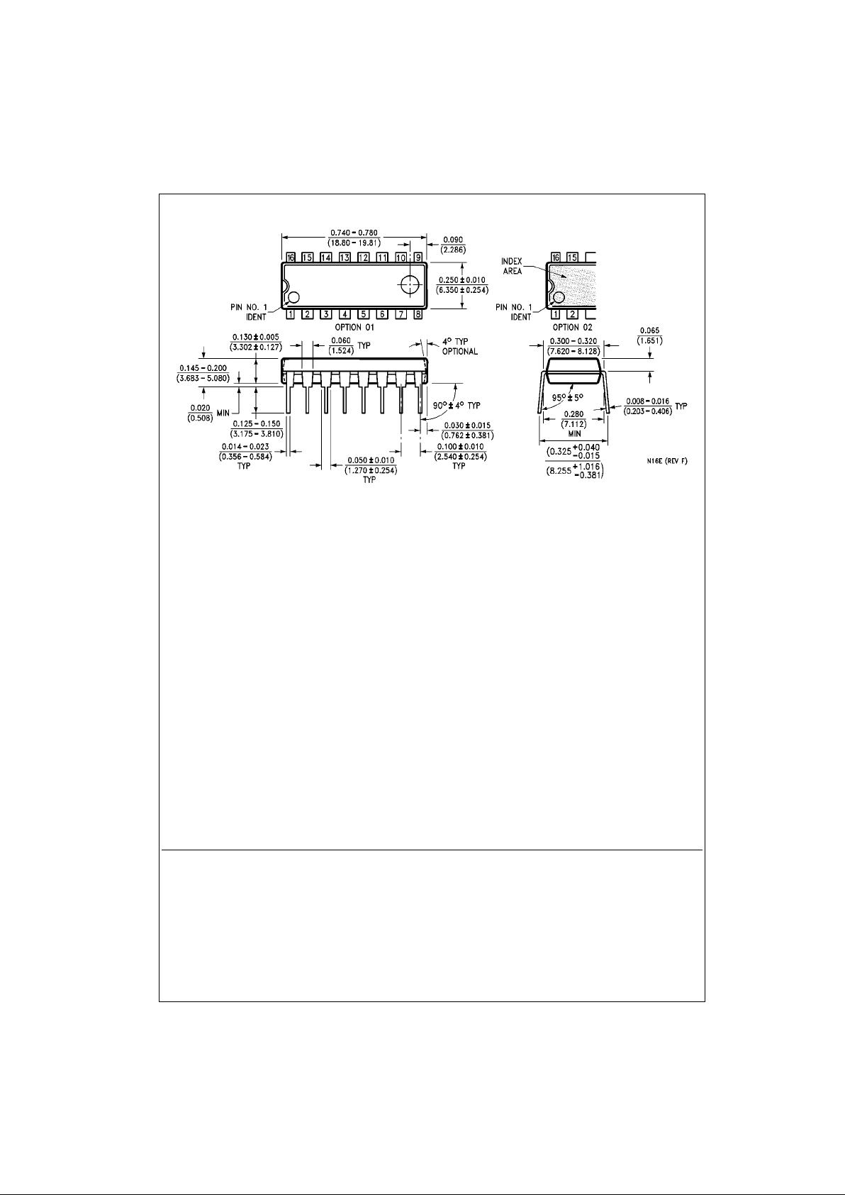
Physical Dimensions inches (millimeters) unless otherwise noted
16-Lead Small Outline Integrated Circuit (SOIC), JEDEC MS-012, 0.150 Narrow
Package Number M16A
Page 6
www.fairchildsemi.com 6
DM74LS670 3-STATE 4-by-4 Register File
Physical Dimensions inches (millimeters) unless otherwise noted (Continued)
16-Lead Plastic Dual-In-Line Package (PDIP), JEDEC MS-001, 0.300 Wide
Package Number N16E
Fairchild does not assume any responsibility for use of any circuitry described, no circuit pate nt licenses are implied and
Fairchild reserves the right at any time without notice to change said circuitry and specifications.
LIFE SUPPORT POLICY
FAIRCHILD’S PRODUCTS ARE NOT AUTHORIZED FOR USE AS CRITICAL COMPONENTS IN LIFE SUPPORT
DEVICES OR SYSTEMS WITHOUT THE EXPRESS WRITTEN APPROVAL OF THE PRESIDENT OF FAIRCHILD
SEMICONDUCTOR CORPORATION. As used herein:
1. Life supp or t de vices o r syste ms are devices or syste ms
which, (a) are intended for surgical implant into the
body, or (b) support or sustain life, and (c) whose failure
to perform when properly used in accordance with
instructions for use provided in the labeling, can be reasonably expected to result in a significant inju ry to the
user.
2. A cr itical compon ent in any componen t of a life su pport
device or system whose failu re to perform can be reasonably expected to ca use the fa i lure of the life su pp ort
device or system, or to affect its safety or effectiveness.
www.fairchildsemi.com
 Loading...