

Page 1
DM74LS194A
4-Bit Bidirectional Universal Shift Register
DM74LS194A 4-Bit Bidirectional Universal Shift Register
August 1986
Revised March 2000
General Description
This bidirectional shif t register is designed to incorp orate
virtually all of the features a system designer may want in a
shift register; they feature p arallel inputs, parallel outputs,
right-shift and left-shi ft serial inputs, operating-mode -control inputs, and a di rect overriding clear lin e. The register
has four distinct modes of operation, namely:
Parallel (broadside) load
Shift right (in the direction Q
Shift left (in the direction Q
Inhibit clock (do nothing)
Synchronous parallel loading is accomplished by applying
the four bits of da ta and taking b oth mode control inputs,
S0 and S1, HIGH. T he data is l oaded into the associated
flip-flops and appear at the outputs after the positive transition of the clock input. During loading, seri al data flow is
inhibited.
Shift right is accomplished synchronously with the rising
edge of the clock pulse when S0 is HIGH a nd S1 is LOW.
Serial data for this mode is entered at the shift-right data
input. When S0 is LOW and S1 is HIGH, data shifts left
synchronously and new data is entered at the shift-left
serial input.
Clocking of the flip-flop is inhibited when both mode control
inputs are LOW.
toward QD)
A
toward QA)
D
Features
■ Parallel inputs and outputs
■ Four operating modes:
Synchronous parallel load
Right shift
Left shift
Do nothing
■ Positive edge-triggered clocking
■ Direct overriding clear
Ordering Code:
Order Number Package Number Package Description
DM74LS194AM M16A 16-Lead Small Outline Integrated Circuit (SOIC), JEDEC MS-012, 0.150 Narrow
DM74LS194AN N16E 16-Lead Plastic Dual-In-Line Package (PDIP), JEDEC MS-001, 0.300 Wide
Devices also availab le in Tape and Reel. Specify by appending th e s uffix let t er “X” to the ordering cod e.
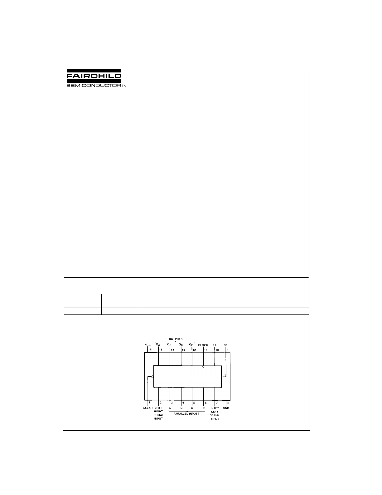
Connection Diagram
© 2000 Fairchild Semiconductor Corporation DS006407 www.fairchildsemi.com
Page 2
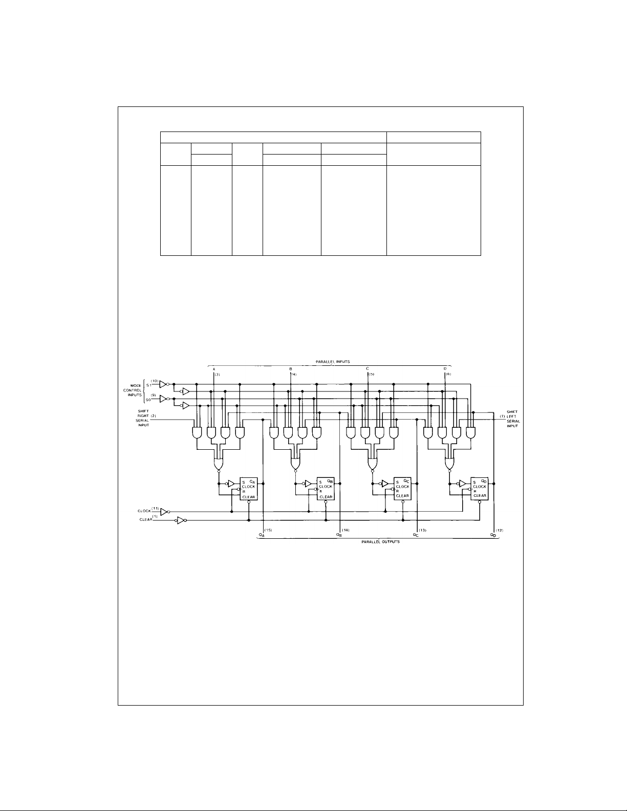
Function Table
Inputs Outputs
DM74LS194A
Clear
Mode
S1 S0 Left Right A B C D
Clock
L X X X X X XXXX L L L L
H X X L X X XXXXQ
Serial Parallel
Q
AQBQCQD
A0QB0QC0QD0
HHH↑ XXabcdabcd
HLH↑ X H XXXX H Q
HLH↑ X L XXXX L QAnQBnQ
HHL ↑ H X XXXXQBnQCnQ
HHL ↑ L X XXXXQ
H L L X X X XXXXQ
H = HIGH Level (steady state)
L = LOW Level (steady state)
X = Don’t Care (any input, including transitions)
↑ = Transition from LOW-to-HIGH lev el
a, b, c, d = The level of steady state input at inputs A, B, C or D, re s pec t iv ely.
, QB0, QC0, QD0 = The level of QA, QB, QC, or QD, respectively, before the indicated steady state input conditions were established.
Q
A0
, QBn, QCn, QDn = The level of QA, QB, QC, respectively, before the most -recent ↑ transition of the clock.
Q
An
BnQCnQDn
A0QB0QC0QD0
Logic Diagram
AnQBnQCn
H
Dn
L
Cn
www.fairchildsemi.com 2
Page 3
Absolute Maximum Ratings(Note 1)
Supply Voltage 7V
Input Voltage 7V
Operating Free Air Temperature Range 0°C to +70°C
Storage Temperature Range −65°C to +150°C
Note 1: The “Absolute Maximum Ratings ” are those val ues beyond w hich
the safety of the device cannot be guaranteed. The device should not be
operated at these limits. The parametric values defined in the Electrical
Characteristics tables are not guaranteed at the absolute maximum ratings.
The “Recommend ed O peratin g Cond itions” t able w ill defin e the condit ions
for actual device operation.
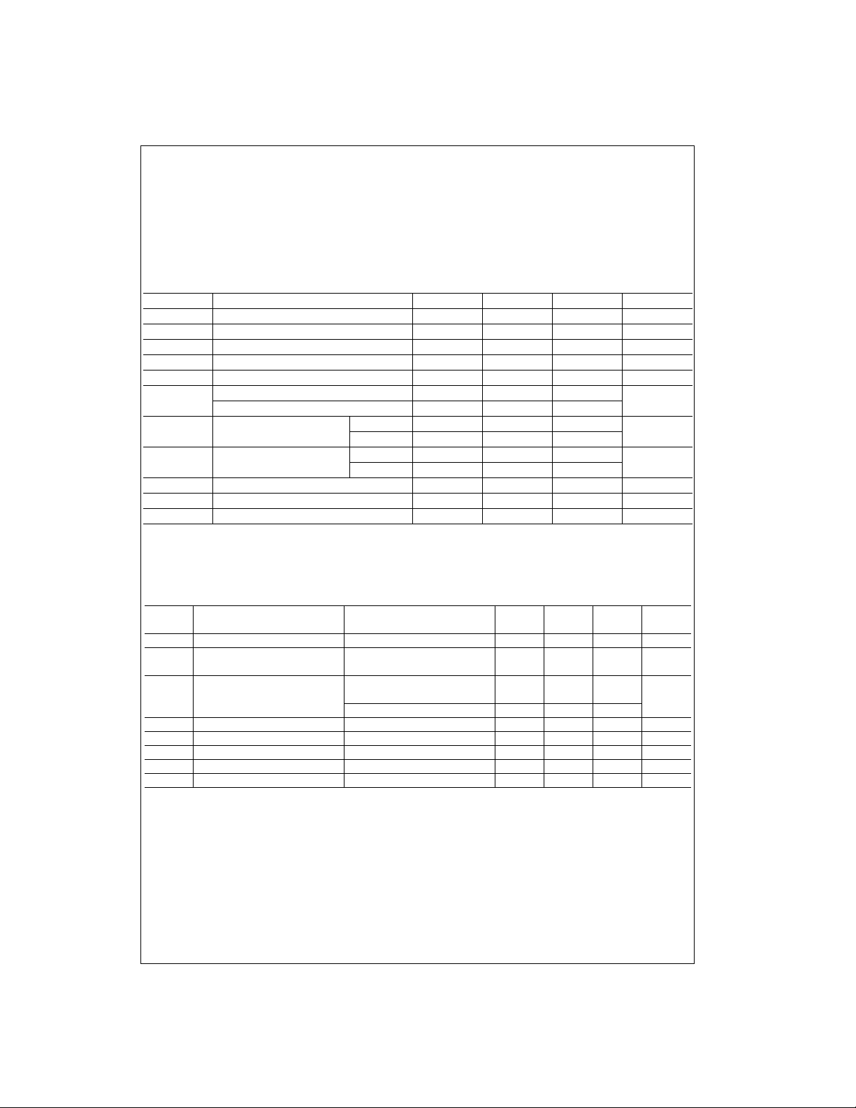
Recommended Operating Conditions
Symbol Parameter Min Nom Max Units
V
CC
V
IH
V
IL
I
OH
I
OL
f
CLK
t
W
t
SU
t
H
t
REL
T
A
Note 2: CL = 15 pF, TA = 25°C and VCC = 5V.
Note 3: C
Note 4: T
Supply Voltage 4.75 5 5.25 V
HIGH Level Input Voltage 2 V
LOW Level In put Voltage 0.8 V
HIGH Level Output Current −0.4 mA
LOW Level Output Current 8 mA
Clock Frequency (Note 2) 0 25
Clock Frequency (Note 3) 0 20
Pulse Width Clock 20
(Note 4) Clear 20
Setup Time Mode 30
(Note 4) Data 20
Hold Time (Note 4) 0 ns
Clear Release Time (Note 4) 25 ns
Free Air Operating Temperature 0 70 °C
= 50 pF, RL = 2 kΩ, TA = 25°C and VCC = 5V.
L
= 25°C and VCC = 5V.
A
DM74LS194A
MHz
ns
ns
Electrical Characteristics
over recommended operating free air temperature range (unless otherwise noted)
Symbol Parameter Conditions Min
V
I
V
OH
V
OL
I
I
I
IH
I
IL
I
OS
I
CC
Note 5: All typicals are at VCC = 5V, TA = 25°C.
Note 6: Not more than one output should be shorted at a time, and the duration should not exc eed one second.
Note 7: With all outputs open, inputs A through D grounded, and 4.5V applied to S0, S1, CLEAR, and the serial inputs, I
then 4.5V applied to CLOCK.
Input Clamp Voltage VCC = Min, II = −18 mA −1.5 V
HIGH Level VCC = Min, IOH = Max
Output Voltage VIL = Max, VIH = Min
LOW Level VCC = Min, IOL = Max
Output Voltage VIL = Max, VIH = Min V
IOL = 4 mA, VCC = Min 0.4
Input Current @ Max Input Voltage VCC = Max, VI = 7V 0.1 mA
HIGH Level Input Current VCC = Max, VI = 2.7V 20 µA
LOW Level Input Current VCC = Max, VI = 0.4V −0.4 mA
Short Circuit Output Current VCC = Max (Note 6) −20 −100 mA
Supply Current VCC = Max (Note 7) 15 23 mA
2.7 3.4 V
3 www.fairchildsemi.com
Typ
(Note 5)
0.35 0.5
is tested with momentary ground,
CC
Max Units
Page 4
Switching Characteristics
at VCC = 5V and TA = 25°C
Symbol Parameter
f
MAX
t
PLH
DM74LS194A
t
PHL
t
PHL
Note 8: All typicals are at VCC = 5V, TA = 25°C.
Note 9: Not more than one output should be shorted at a time, and the duration should not exceed one second.
Note 10: With all outputs ope n, inputs A through D grounded, a nd 4.5V ap plied to S0 , S1, CLEA R, and the serial inpu ts, I
ground, then 4.5V applied to CLOCK.
Maximum Clock Frequency 20 MHz
Propagation Delay Time Clock to Any Q
LOW-to-HIGH Level Output
Propagation Delay Time Clock to Any Q
HIGH-to-LOW Level Output
Propagation Delay Time Clear to Any Q
HIGH-to-LOW Output
From (Input)
To (Output) Min Max
CL = 50 pF, RL = 2 kΩ
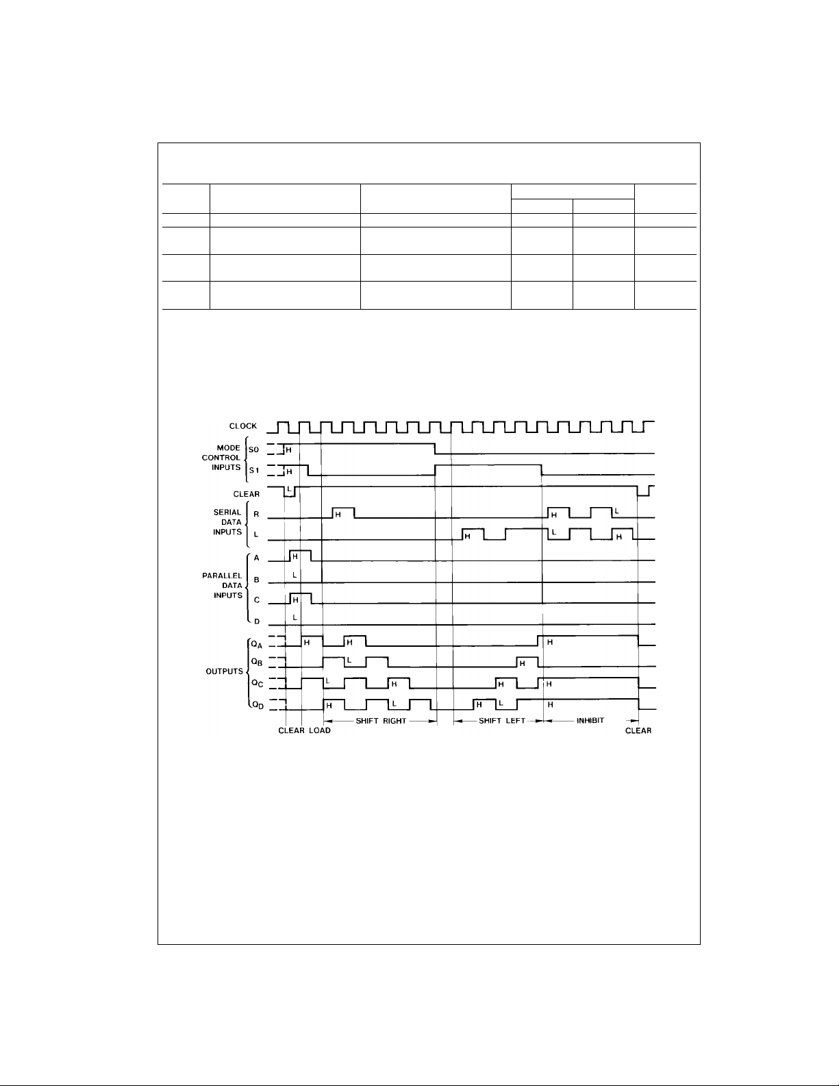
Timing Diagram
Typical Clear, Load, Right-Shift, Left-Shift, Inhibit, and Clear Sequences
Units
26 ns
35 ns
38 ns
is tested with momentary
CC
www.fairchildsemi.com 4
Page 5
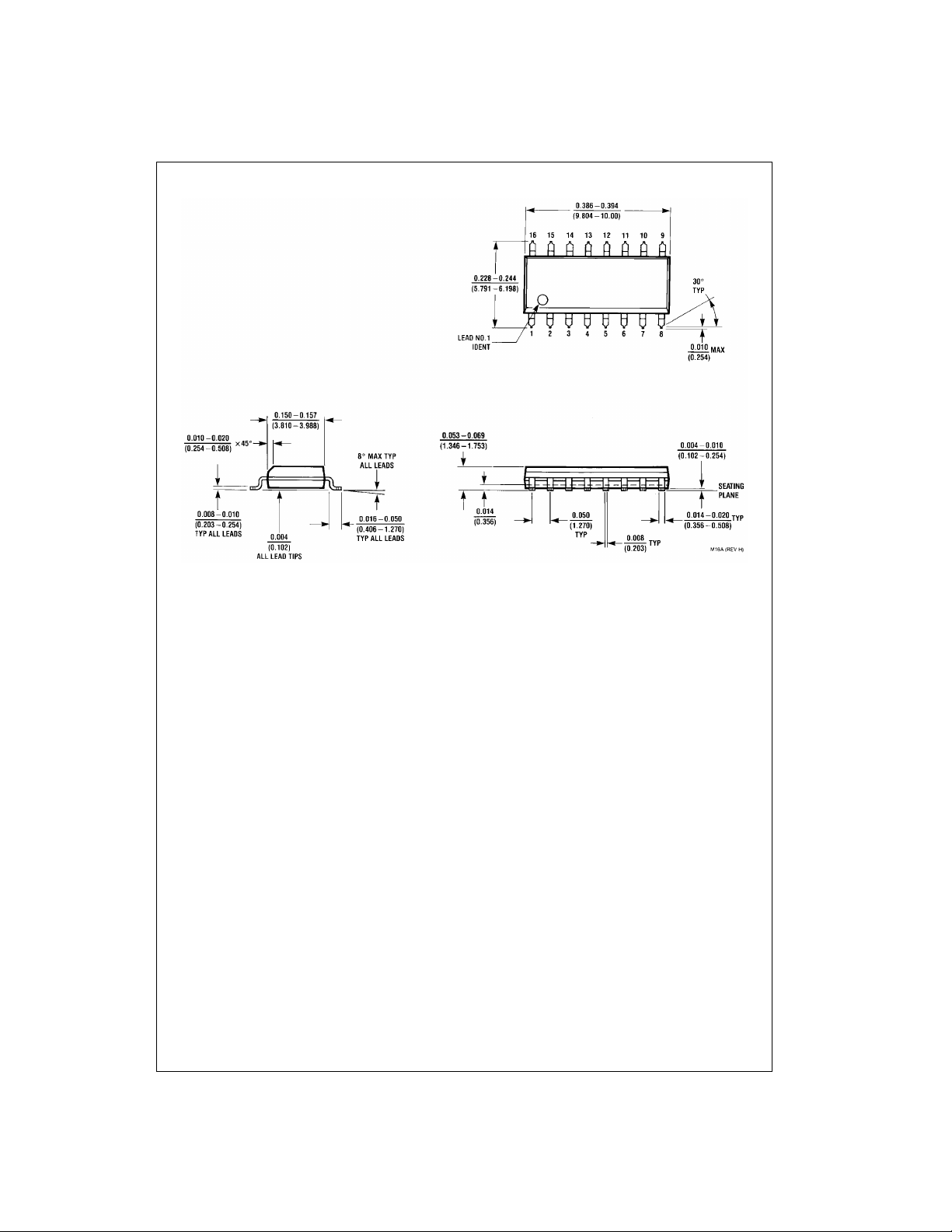
Physical Dimensions inches (millimeters) unless otherwise noted
DM74LS194A
16-Lead Small Outline Integrated Circuit (SOIC), JEDEC MS-012, 0.150 Narrow
Package Number M16A
5 www.fairchildsemi.com
Page 6
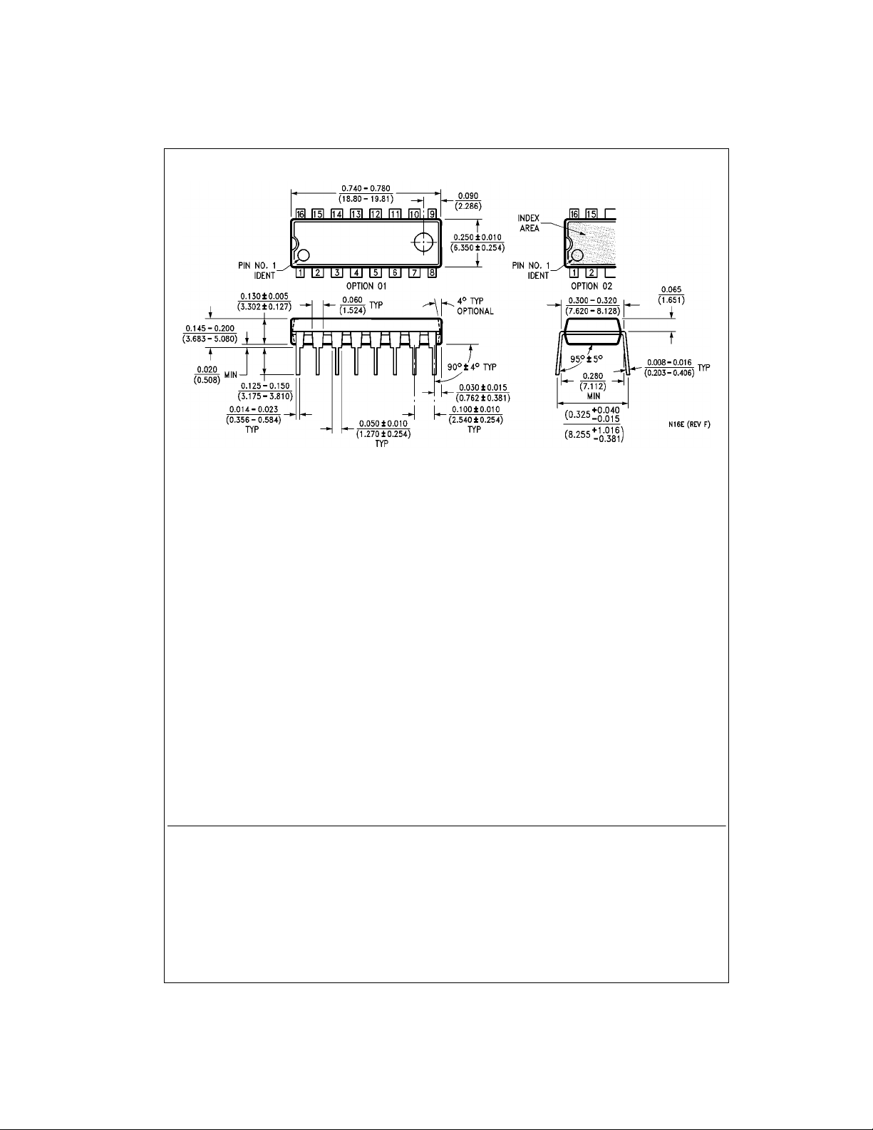
Physical Dimensions inches (millimeters) unless otherwise noted (Continued)
16-Lead Plastic Dual-In-Line Package (PDIP), JEDEC MS-001, 0.300 Wide
Package Number N16E
DM74LS194A 4-Bit Bidirectional Universal Shift Register
Fairchild does not assume any responsibility for us e of any circuitry described, no circuit patent licenses are implied and
Fairchild reserves the right at any time without notice to change said circuitry and specifications.
LIFE SUPPORT POLICY
FAIRCHILD’S PRODUCTS ARE NOT AUTHORIZED FOR USE AS CRITICAL COMPONENTS IN LIFE SUPPORT
DEVICES OR SYSTEMS WITHOUT THE EXPRESS WRITTEN APPROVAL OF THE PRESIDENT OF FAIRCHILD
SEMICONDUCTOR CORPORATION. As used herein:
1. Life support devices o r syste ms are devices or syste ms
which, (a) are intended for surgical implant into the
body, or (b) support or sustain life, and (c) whose failure
to perform when properly used in accordance with
instructions for use provided in the labeling, can be reasonably expected to result in a significan t injury to the
user.
2. A critical compon ent in any compon ent of a lif e supp ort
device or system whose failu re to perform can be reasonably expected to ca use the fa i lure of the li fe su pp ort
device or system, or to affect its safety or effectiveness.
www.fairchildsemi.com
www.fairchildsemi.com 6
 Loading...