

Page 1
© 2000 Fairchild Semiconductor Corporation DS006225 www.fairchildsemi.com
September 1986
Revised February 2000
DM74ALS564A Octal D-Type Edge-Triggered Flip-Flop with
DM74ALS564A
Octal D-Type Edge-Triggered Flip-Flop with
3-STATE Outputs
General Description
These 8-bit register s feature totem-pole 3- STATE outp uts
designed specifically fo r driving highly-capacitive or relatively low-impedance loa ds. Th e hi gh -im ped ance state and
increased high-logic-level drive provide these registers with
the capability of being connected directly to and driving the
bus lines in a bu s-or ga nized sy stem w ith ou t n eed fo r interface or pull-up components. They are particularly attractive
for implementing buffer registers, I/O ports, bidirectional
bus drivers, and working registers.
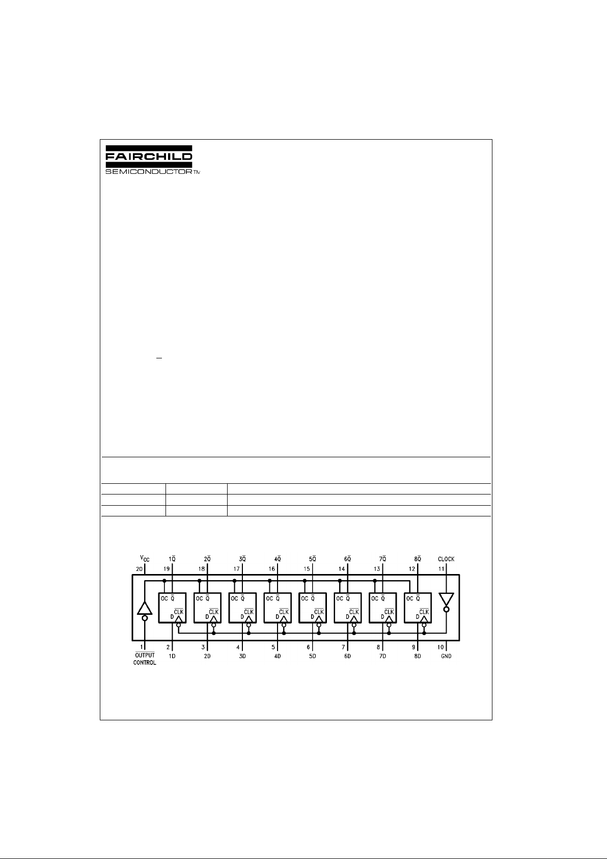
The eight flip-flops of the DM74ALS564A are edge-triggered inverting D-type flip-fl ops. On the positive transition
of the clock, the Q
outputs will be set to the complement of
the logic states that were set up at the D inputs.
A buffered output control input ca n be used to place the
eight outputs in either a normal l ogic state (HIGH or LOW
logic levels) or a high-impedance state. In the high-impedance state the outputs ne ither load nor dr ive the bus lines
significantly.
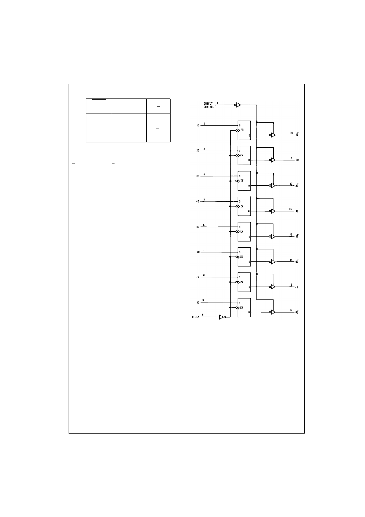
The output control does not affect the i nternal oper ation of
the flip-flops. That is, the old data can be retained or new
data can be entered even while the outputs are OFF.
Features
■ Switching specifications at 50 pF
■ Switching specifications guaranteed over full tempera-
ture and V
CC
range
■ Advanced oxide-isolated, ion-implanted Schottky TTL
process
■ 3-STATE buffer-type outputs drive bus lines directly
Ordering Code:
Devices also availab le in Tape and Reel. Specify by appending th e s uffix let t er “X” to the ordering code.
Connection Diagram
Order Number Package Number Package Description
DM74ALS564AWM M20B 20-Lead Small Outline Integrated Circuit (SOIC), JEDEC MS-013, 0.300 Wide
DM74ALS564AN N20A 20-Lead Plastic Dual-In-Line Package (PDIP), JEDEC MS-001, 0.300 Wide
Page 2
www.fairchildsemi.com 2
DM74ALS564A
Function Table
L = LOW State
H = HIGH State
X = Don’t Care
↑ = Positive Edge Transition
Z = High Impedance State
Q
0
= Previous Condit ion of Q
Logic Diagram
Output Clock D Output
Control Q
L ↑ HL
L ↑ LH
LLXQ
0
HXXZ
Page 3

3 www.fairchildsemi.com
DM74ALS564A
Absolute Maximum Ratings(Note 1)
Note 1: The “Absolute M aximu m R atin gs” are t hose valu es b eyo nd w hich
the safety of the device cannot be guaranteed. The device should not be
operated at these limits. The parametric values defined in the Electrical
Characteristics tables are not guaranteed at the absolute maximum ratings.
The “Recommend ed O peratin g Cond itions” t able w ill defin e the condition s
for actual device operation.
Recommended Operating Conditions
Note 2: This product meets application requirements of 500 temp erature cycles from −65°C to +150°C.
Note 3: The (↑) arrow indicates t he positive edge of the Clo c k is us ed for reference.
Electrical Characteristics
over recommended operating free air temperature range. All typical values are measured at VCC = 5V, TA = 25°C.
Supply Voltage 7V
Input Voltage 7V
Voltage Applied to Disabled Output 5.5V
OperatingFree Air Temperature Range 0°C to +70°C
Storage Temperature Range −65°C to +150°C
Typical θ
JA
N Package 56.0°C/W
M Package 75.0°C/W
Symbol Parameter Min Nom Max Units
V
CC
Supply Voltage 4.5 5 5.5 V
V
IH
HIGH Level Input Voltage 2 V
V
IL
LOW Level Input Voltage 0.8 V
I
OH
HIGH Level Output Current −2.6 mA
I
OL
LOW Level Output Current 24 mA
f
CLOCK
Clock Frequency 0 30 MHz
t
W
Width of Clock Pulse HIGH 14 ns
LOW 14 ns
t
SU
Data Setup Time (Note 3) 15↑ ns
t
H
Data Hold Time (Note 3) 0↑ ns
T
A
Free Air Operating Temperature 0 70 °C
Symbol Parameter Conditions Min Typ Max Units
V
IK
Input Clamp Voltage VCC = 4.5V, II = −18 mA −1.2 V
V
OH
HIGH Level VCC = 4.5V
IOH = Max 2.4 3.2 V
Output Voltage VIL = VILMax
VCC = 4.5V to 5.5V IOH = −400 µAVCC − 2V
V
OL
LOW Level VCC = 4.5V IOL = 12 mA 0.25 0.4 V
Output Voltage VIH = 2V IOL = 24 mA 0.35 0.5 V
I
I
Input Current @ Maximum
VCC = 5.5V, VIH = 7V 0.1 mA
Input Voltage
I
IH
HIGH Level Input Current VCC = 5.5V, VIH = 2.7V 20 µA
I
IL
LOW Level Input Current VCC = 5.5V, VIL = 0.4V −0.2 mA
I
O
Output Drive Current VCC = 5.5V, VO = 2.25V −30 −112 mA
I
OZH
OFF-State Output Current VCC = 5.5V, VIH = 2V
20 µA
HIGH Level Voltage Applied VO = 2.7V
I
OZL
OFF-State Output Current VCC = 5.5V, VIH = 2V
−20 µA
LOW Level Voltage Applied VO = 0.4V
I
CC
Supply Current VCC = 5.5V Outputs HIGH 10 18 mA
Outputs OPEN Outputs LOW 15 24 mA
Outputs Disabled 16 30 mA
Page 4

www.fairchildsemi.com 4
DM74ALS564A
Switching Characteristics
over recommended operating free air temperature range
Symbol Parameter Conditions From To Min Max Units
f
MAX
Maximum Clock Frequency VCC = 4.5V to 5.5V 30 MHz
t
PLH
Propagation Delay Time RL = 500Ω
Clock Any Q 414ns
LOW-to-HIGH Level Output CL = 50 pF
t
PHL
Propagation Delay Time
Clock Any Q 414ns
HIGH-to-LOW Level Output
t
PZH
Output Enable Time Output
Any Q 418ns
to HIGH Level Output Control
t
PZL
Output Enable Time Output
Any Q 418ns
to LOW Level Output Control
t
PHZ
Output Disable Time Output
Any Q 210ns
from HIGH Level Output Control
t
PLZ
Output Disable Time Output
Any Q 315ns
from LOW Level Output Control
Page 5

5 www.fairchildsemi.com
DM74ALS564A
Physical Dimensions inches (millimeters) unless otherwise noted
20-Lead Small Outline Integrated Circuit (SOIC), JEDEC MS-013, 0.300 Wide
Package Number M20B
Page 6

www.fairchildsemi.com 6
DM74ALS564A Octal D-Type Edge-Triggered Flip-Flop with
Physical Dimensions inches (millimeters) unless otherwise noted (Continued)
20-Lead Plastic Dual-In-Line Package (PDIP), JEDEC MS-001, 0.300 Wide
Package Number N20A
Fairchild does not assume any responsibility for use of any circuitry described, no circuit pate nt licenses are implied and
Fairchild reserves the right at any time without notice to change said circuitry and specifications.
LIFE SUPPORT POLICY
FAIRCHILD’S PRODUCTS ARE NOT AUTHORIZED FOR USE AS CRITICAL COMPONENTS IN LIFE SUPPORT
DEVICES OR SYSTEMS WITHOUT THE EXPRESS WRITTEN APPROVAL OF THE PRESIDENT OF FAIRCHILD
SEMICONDUCTOR CORPORATION. As used herein:
1. Life support devices or systems are devices or syste ms
which, (a) are intended for surgical implant into the
body, or (b) support or sustain life, and (c) whose failure
to perform when properly used in accordance with
instructions for use provided in the labeling, can be reasonably expected to result in a significant inju ry to the
user.
2. A critical component i n any compon ent of a lif e support
device or system whose failu re to perform can be reasonably expected to ca use the fa i lure of the life su pp ort
device or system, or to affect its safety or effectiveness.
www.fairchildsemi.com
 Loading...