

Page 1
1
DESCRIPTION
The single output DGP30 Series is designed to accept an extended
2:1 input voltage range for use in industrial and telecom
applications. The output of the converter is electrically isolated,
thereby allowing the output to be configured as a positive or
negative output voltage. For additional system utility output Trim
and Remote ON/OFF are featured. Overcurrent protection,
overtemperature protection, and output overvoltage transient
protection allow safe, reliable operation.
FEATURES
• Remote ON/OFF and TRIM
• Low OFF Current
• Overcurrent and Overtemperature Protection
• Efficiencies to 86%
• Transient Output Overvoltage Protection
• 1544V Isolation
• Five-Side Shielded Case
• Extended Range Input (2:1)
DGP30 SERIES
SINGLE OUTPUT
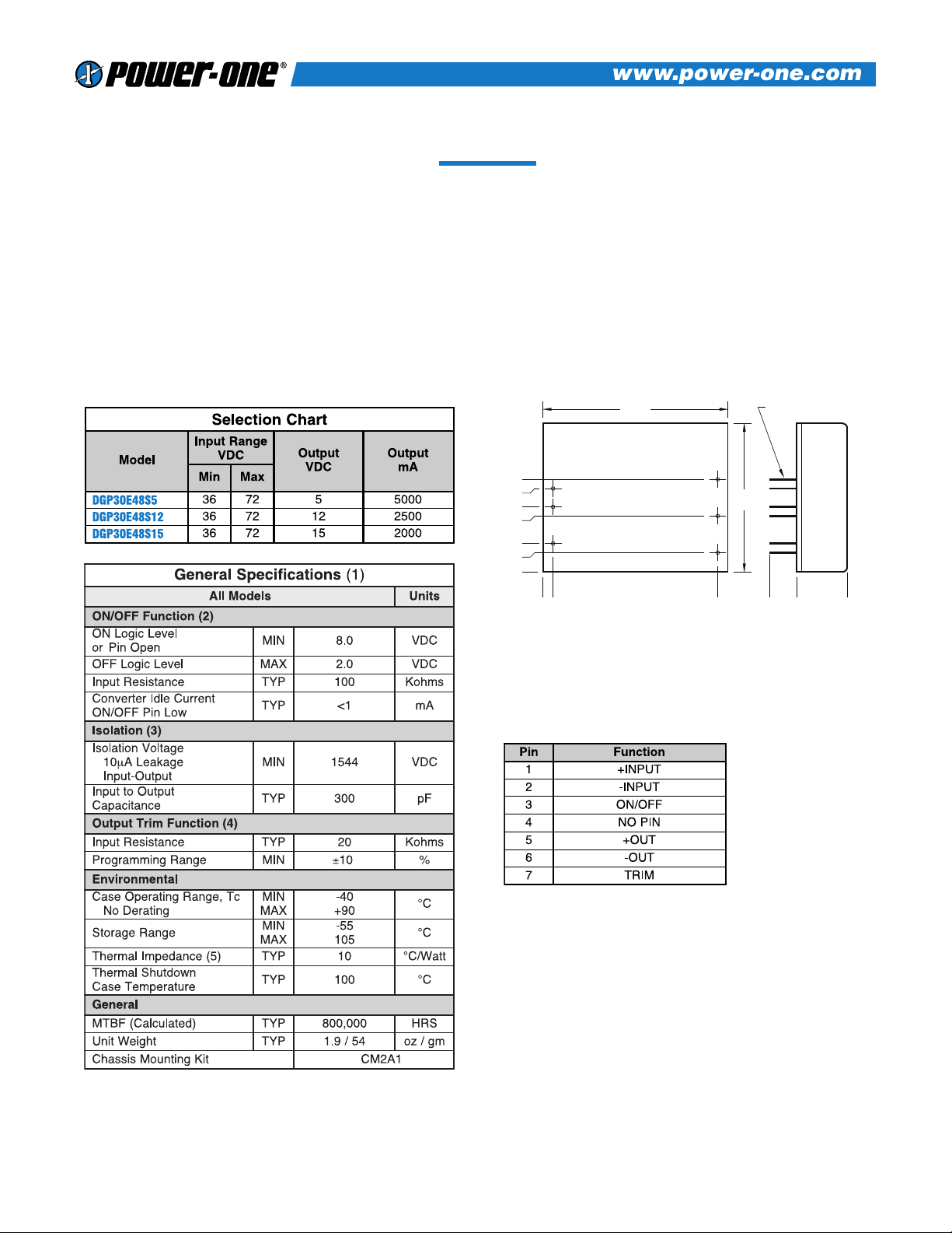
Mechanical tolerances unless otherwise noted:
X.XX dimensions: ±0.020 inches
X.XXX dimensions: ±0.005 inches
NOTES
(1) All parameters measured at Tc = 25°C, nominal input voltage and full rated load unless otherwise noted.
Refer to the Technical Reference Section for the definition of terms, measurement circuits and other
information.
(2) ON/OFF pin is referenced to pin 2, -Input. See DGP30 Series Application Notes for the specific
requirements of this feature.
(3) The Case is electrically connected to Pin 1, +Input.
(4) Full output trim range may not be available at minimum input voltage and full load. Full trim is
guaranteed from minimum input voltage, plus 5%, and full load.
(5) The case thermal impedance is specified as the case temperature rise over ambient per package watt
dissipated.
1
BOTTOM VIEW SIDE VIEW
0.000
0.000
0.3
0.000
2.02
(51.31)
(7.62)
0.040 (1.02) DIA
6 PLACES
0.55
1.62
(13.97)
(41.15)
2
3
7
6
5
1.800
0.11
0.700
0.400
0.100
0.600
0.300
0.31
(10.16)
(2.54)
(7.62)
(7.9)
(17.78)
(15.24)
(2.8)
(45.72)
Rev. 04/2000
Page 2
2
DGP30 SERIES – SINGLE OUTPUT
NOTES
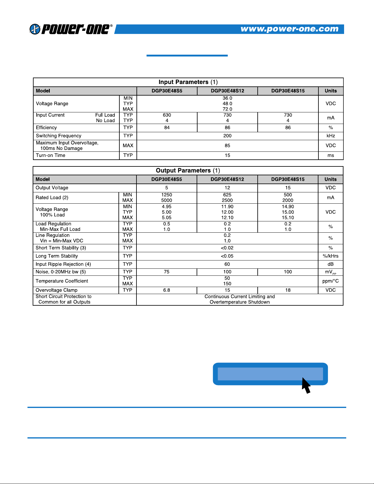
(1) All parameters measured at Tc=25 °C case temperature, nominal input voltage and full rated load
unless otherwise noted. Refer to the Technical Reference Section for definition of terms,
measurement circuits and other information.
(2) Minimum load required for rated regulation only. Module will not be damaged if run at less than
minimum load.
(3) Short term stability is specified after a 30 minute warm-up at full load, and with constant line, load
and ambient conditions.
(4) The input ripple rejection is specified for DC to 120Hz ripple with a modulation amplitude of 1% Vin.
(5) Noise is measured per Technical Reference Section. Output noise is measured with a 1µF tantalum
capacitor connected 1” from the output pins.
www.power-one.com
www.power-one.com
For the Most Up-To-Date Information
24 Hours/Day—7 Days/Week
NUCLEAR AND MEDICAL APPLICATIONS Power-One products are not authorized for use as critical components in life support systems, equipment used in hazardous environments,
or nuclear control systems without the express written consent of the President of Power-One, Inc.
TECHNICAL REVISIONS The appearance of products, including safety agency certifications pictured on labels, may change depending on the date manufactured. Specifications are
subject to change without notice.
Page 3
3
DGP30 SERIES – SINGLE OUTPUT
DGP30 SERIES APPLICATION NOTES:
External Capacitance Requirements
No external capacitance is required for operation of the DGP30
Series. However, it is recommended that the DGP30 Series use a
capacitor of sufficient ripple current capacity connected across the
input pins if a capacitive input source is farther than 1” from the
converter. To meet the reflected ripple requirements of the
converter, an input impedance of less than 0.05 Ohms from DC to
200KHz is required. External output capacitance is not required
for operation, however it is recommended that 1F to 10F of
tantalum and 0.001 to 0.1F ceramic capacitance be selected for
reduced system noise. Additional output capacitance may be
added for increased filtering, but should not exceed 400F.
Negative Outputs
A negative output voltage may be obtained by connecting the
+OUT to circuit ground and connecting -OUT as the negative
output.
Remote ON/OFF Operation
The remote ON/OFF pin may be left floating if this function is
not used. It is recommended to drive this pin with an open
collector arrangement or a relay contact. When the ON/OFF pin
is pulled low with respect to the -INPUT, the converter is placed
in a low power drain state. Since the ON/OFF pin is driven by a 9
volt internal source via a 100K resistor, the pin should not be
driven by TTL logic. Attempts to drive this circuit with logic
circuits may result in damage to user circuitry.
Output TRIM
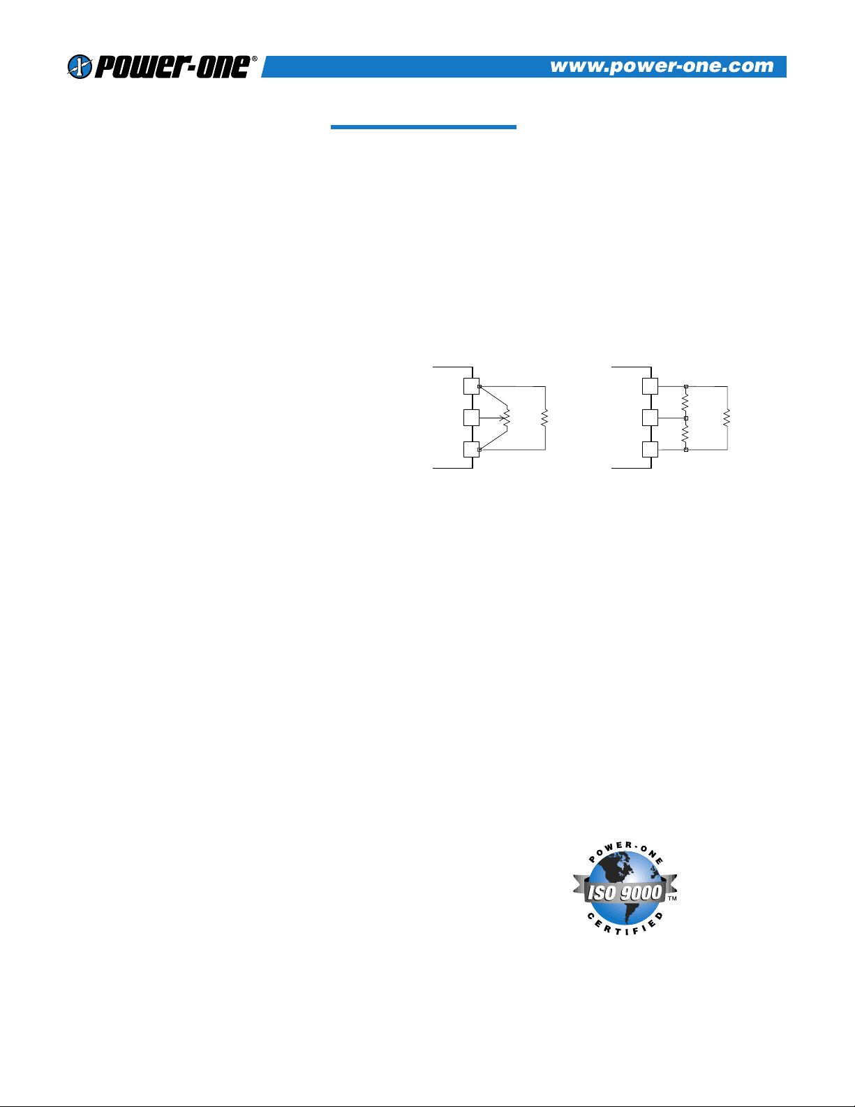
The TRIM pin may be used to adjust the output ±5% from the
nominal setting. This function allows adjustment for voltage drops
in the system wiring, as well 5.2 volt outputs for ECL applications.
Figure 1 shows the proper connections to use this function. A
trimpot value of 10K should be used for the 5 volt output.
A trimpot value of 20K should be used for 12 and 15 volt outputs.
If the TRIM function is not required the pin may be left floating.
5
+OUT
7
TRIM 10K LOAD
USING TRIMPOT
6
-OUT
5
+OUT
7
TRIM
TRIM
DOWN
TRIM
UP
LOAD
USING FIXED RESISTORS
6
-OUT
Figure 1.
Page 4
4
DGP30 SERIES – SINGLE OUTPUT
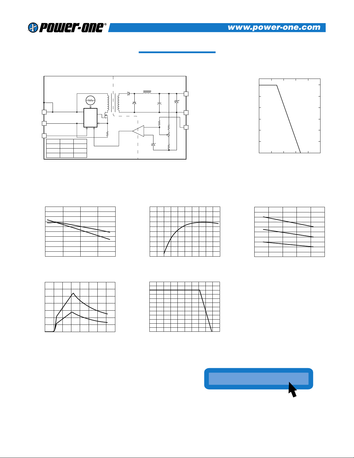
DGP30 SERIES BLOCK DIAGRAM
5
+ OUTPUT
SHIELDED ISOLATION TRANSFORMER
+
6
7
TRIM
ISOLATED
FEEDBACK
LOW TC
BANDGAP
REFERENCE
SIX SIDED SHIELDED COPPER CASE
+
–
2
– INPUT
ON/OFF
ON/OFF C D
5 270F6.8V
12 40F 15V
15 40F 18V
1
3
+ INPUT
CURRENT
MODE
PWM
THERMAL SHUTDOWN
D
C
- OUT
35
0
5
10
15
20
25
30
40 45 50 55 60
OUTPUT POWER DERATING
AMBIENT TEMPERATURE
POWER OUTPUT
90
85
86
87
88
89
80
81
82
83
84
35 6555
100% LOAD
50% LOAD
45 75
EFFICIENCY Vs. LINE INPUT VOLTAGE
LINE INPUT (VOLTS)
EFFICIENCY (%)
90
85
89
88
87
86
84
83
82
81
80
080
905020 30 40 60 7010 100
EFFICIENCY Vs. LOAD
LOAD (%)
EFFICIENCY (%)
1.2
100% LOAD
75% LOAD
50% LOAD
0.7
0.2
0.3
0.4
0.5
0.6
0.8
0.9
1.0
1.1
30 70
40 50 60 80
INPUT RIPPLE Vs. LINE INPUT VOLTAGE
LINE INPUT (VOLTS)
INPUT RIPPLE (RMS)
1.4
100% LOAD
50% LOAD
0.0
0.4
0.2
0.6
0.8
1.0
1.2
070
10 20 30 40 50 60 80
INPUT CURRENT Vs. LINE INPUT VOLTAGE
LINE INPUT (VOLTS)
INPUT CURRENT (AMPS)
120
0
40
10
20
30
50
60
70
80
90
100
110
0 180
20 40 60 80 100 120 140 160 200
OUTPUT VOLTAGE Vs. OUTPUT LOAD
OUTPUT LOAD (%)
OUTPUT VOLTAGE (%)
Typical Performance: (Tc=25°C, Vin=Nom VDC, Rated Load)
www.power-one.com
www.power-one.com
For the Most Up-To-Date Information
24 Hours/Day—7 Days/Week
 Loading...