

Page 1

*H
Text Script for “Development Tools Overview”
Table of Contents
Introduction ............................................................................................................... Slide 1
MPLAB
MPSIM™ Simulator .................................................................................................... Slide 3
MPLAB
MPLAB ICE Features .................................................................................................. Slide 5
Knowledge Check #1 ................................................................................................. Slide 6
MBLAB C17/C18 Compilers ........................................................................................ Slide 7
Third Party Compilers ................................................................................................ Slide 8
In-Circuit Debugger (ICD) ........................................................................................... Slide 9
Knowledge Check #2 ................................................................................................Slide 10
PICSTART
PRO MATE
Knowledge Check #3 ................................................................................................Slide 13
PICDEM™ evaluation boards ....................................................................................Slide 14
PICDEM.net™ ...........................................................................................................Slide 15
ROMless Development Board ...................................................................................Slide 16
USB Development Board ..........................................................................................Slide 17
PICDEM MSC1 ...........................................................................................................Slide 18
Knowledge Check #4 ................................................................................................Slide 19
MXLAB™ Mixed Signal Development Tool ...............................................................Slide 20
FilterLab™ Software .................................................................................................Slide 21
CAN Developer’s Kit .................................................................................................Slide 22
Infrared Development Kit ..........................................................................................Slide 23
Fan Controller Development Boards .........................................................................Slide 24
Thermal Sensor Demo Board ....................................................................................Slide 25
The KEELOQ
microID
Serial EEPROM Designer’s Kit ..................................................................................Slide 28
Total Endurance™ Software .....................................................................................Slide 29
Third Party Development Tools ................................................................................Slide 30
Knowledge Check #5 ................................................................................................Slide 31
Closing Slide .............................................................................................................Slide 32
®
Integrated Environment for PIC MCU Development ..................................... Slide 2
®
ICE 2000 Overview ....................................................................................... Slide 4
®
Plus .......................................................................................................Slide 11
®
II ............................................................................................................Slide 12
®
™
Evaluation Kit ....................................................................................Slide 26
Developer’s Kit ..........................................................................................Slide 27
Page 2
Slide 1: Title Slide
Development Tools Overview
Thank you for joining Microchip’s Development Tools Overview course.
This session gives an overview of the development tools that support Microchip’s complete
portfolio of products.
Page 3
Slide 2: Architecture Overview
Development Tools Overview
MPLAB IDE
MPLAB
Integrated Development Environment (IDE)
®
Plus
Project
Manager
Third Party
ToolsProgrammers
· Compilers
· Programmers
· Emulators
· Dev Boards
· Training Tools
MPASM
Assembler
MPLINK
Object Linker
MPLIB
Object Librarian
®
®
®
Built in
Editor
MPSIM™
Simulator
Source Level
Debugger
Emulators/
DebuggersSimulatorsLanguages
MPLAB ICE
In-Circuit Emulator
· ICE 2000
· ICEPIC™
MPLAB ICD
In-Circuit Debugger
PICSTART®
Development
Programmer
PRO MATE® II
Production Quality
Programmer
C Compilers
· MPLAB C17
· MPLAB C18
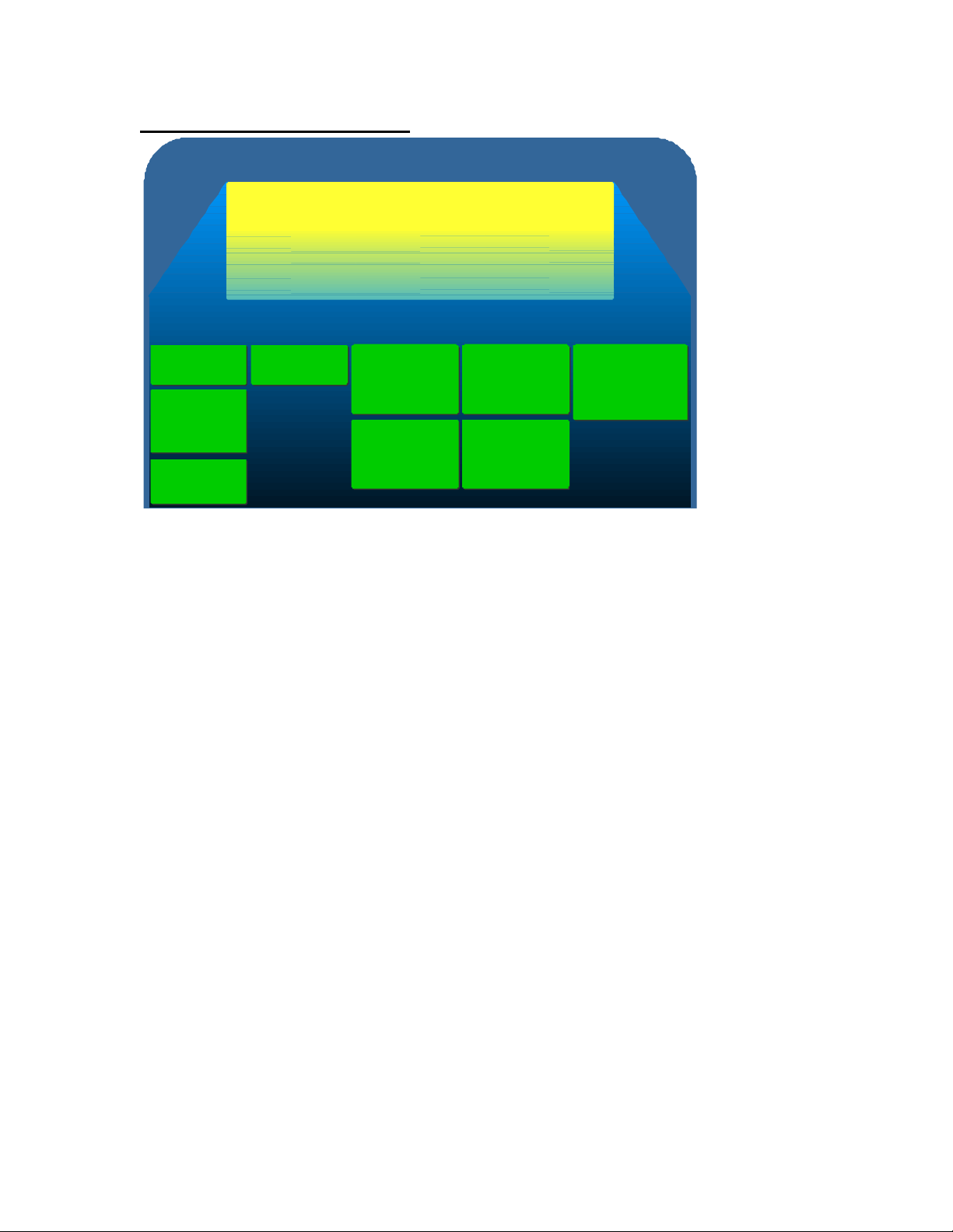
The MPLAB® Integrated Development Environment, or IDE, can be looked at as the foundation of
many of Microchip’s other PIC® microcontroller development tools. MPLAB IDE contains a builtin editor, source level debugger, and project manager and also acts as the interfac e for the
included built-in MPASM™ Assembler, and Linker / Librarian facilities. The IDE is also the front end for Microchip C compilers and integrated Third Party C compilers.
The IDE contains a built-in software instruction simulator and it implement s most of the PIC MCU
peripherals. The IDE is also the front -end for the real -time in-circuit emulators including
Microchip’s MPLAB ICE 2000 and the Third Party ICEPIC™ Emulator.
Also running under the IDE is the real-time In -Circuit Debugger (ICD) and Microchip’s
programmers including the PICSTART® Plus Development Programmer and the PRO MATE® II
Production Quality Programmer.
The beauty of MPLAB, which contains the assembler, simulator, editor, and debugger, is that its
available free. It is not licensed software, and you can always go to www.microchip.com and
download the latest version.
Page 4

Slide 3: MPSIM™ Simulator
Development Tools Overview
MPSIM - Simulator
Microchip's MPSIM simulator - Its free!
- Single Step through code
- Unlimited breakpoints
- Unlimited trace capability
- Examine/Modify all registers
- Stopwatch feature that calculates time and instruction
cycles for a section of code
- Use pin/register stimulus functions to test code, including
A/D functions
Included in the MPLAB IDE is the discrete event instruction MPSIM™ simulator. The simulator
let’s you single step through source code, while providing unlimited breakpoint capability,
unlimited trace capability and the ability to modify and examine all of the internal variables and
watch registers. The simulator also provides real-time time stamping so you can see how long
your code takes to execute and it also supports stimulus injection so you can inject I/O pin
stimulus or A/D register stimulus files. These stimulus features allow you to run your code and
test an algorithm based on a certain input signal waveform.
Register stimulus files enable you to specify a waveform that can be generated by tools like
Microsoft Excel. Your code, when executed, can then be validated using a particular register
stimulus file. This is particularly valuable when simulating an A/D converter, allowing you to
simulate analog waveforms.
Page 5
Slide 4: MPLAB® ICE 2000 Overview
Development Tools Overview
MPLAB ICE 2000 Overview
Supports PICmicro MCUs up to 64K words
Full speed emulation up to 25Mhz on 18xxx devices
Supports other PICmicro MCUs up to 20Mhz
Communicates to PC via the parallel port
Interfaces to MPLAB IDE
Emulator Pod
Processor
Module
Device Adapter
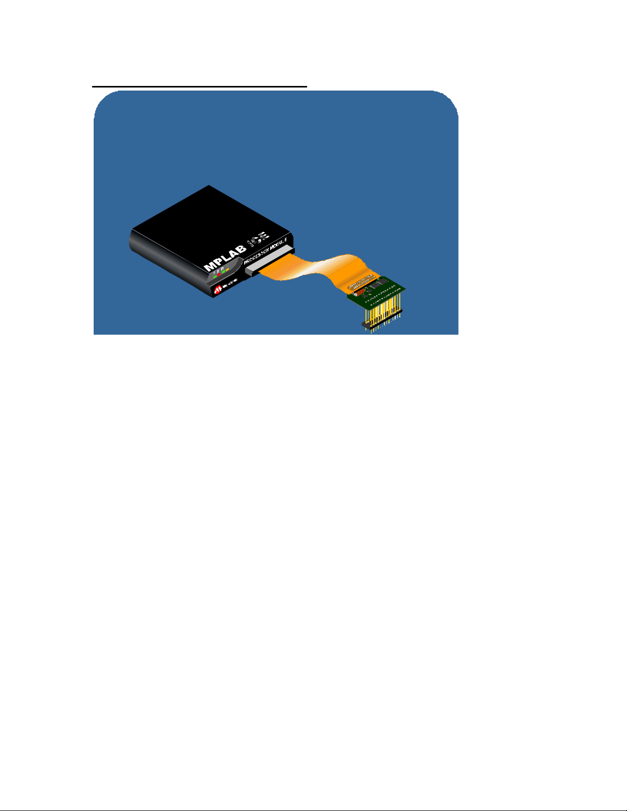
The MPLAB In-Circuit Emulator, the ICE 2000, supports most of the PIC MCUs with up to 64K
words of program memory space. It provides full speed emulation of PIC18 devices up to 25MHz
and supports other devices up to 20 MHz. The ICE 2000 communicates to the PC through the
parallel port interface while the user is running MPLAB IDE. The ICE consists of three standard
elements: an emulator pod, a processor module, and a device adapter. In addition, transition
sockets are available for designs using surface mount devices.
The emulator pod is a universal system and remains the same regardless of the device you are
using. The pod contains the trace memory, breakpoint logic, complex trigger and trace logic, and
RAM in place of program memory. The processor module for the device you are using slides into
a slot in the pod.
The processor module will support a number of different devices depending on which
microcontroller family you select. The device adapter then plugs into the processor module via a
flex cable.
The device adapter is pin-out specific and available in configurations from 8 pins up to 84 pins. If
your microcontroller is a surface mount device and uses an SO or a TQFP package, an SOIC
transition socket is available which will solder down on your board in place of the actual device.
The device adapter then plugs directly into the surface mount transition socket. Since the ICE
2000 is universal, you can purchase the pod, processor module and device adapter for a specific
microcontroller and easily migrate to a device within the same family by just purchasing a new
device adapter. For emulation of another family of PICmicro MCUs, a processor module and
device adapter will be required.
The ICE 2000 supports low-voltage emulation from 2.5 volts to 5.5 volts using the voltage level
from the actual target board. The user can select the oscillator from the target board or use an
internal software programmable clock that can generate frequencies anywhere from 32 kHz up to
the max imum operating frequency of the device. The internal clock is a PLL that can be set in fine
increments thus enabling the user to test various target frequencies to optimize software
execution speed, power consumption and crystal selection.
Page 6

Slide 5: MPLAB ICE Features
Development Tools Overview
MPLAB ICE Features
Extensive Trace Capabilities
- 32K trace buffer
- Traces all registers
- Time Stamping
- Set breakpoints on register access
Four level conditional break/trace/trigger
- Pass counter triggers after n events
- Trigger conditions can be ANDed together
- Trigger order can be specified
- Trigger conditions can be ORed together
Measure time between events
Code coverage to find untested code
The ICE 2000 has extensive trace capabilities, featuring a 32 Kb trace buffer which can trace 8bits of logic analyzer input. The trace buffer not only traces program memory, instruction and its
address, but also includes access to internal registers including general purpose file registers and
peripheral registers.
The ICE2000 can set breakpoints when any internal register is written to or read from. A
breakpoint can also be set to trigger when writing a specific value, a specific bit, or a set of bits.
The trace buffer contains a timestamp with a real -time instruction execution clock. The
timestamp feature displays when each instruction is executed in instruction cycles or in actual
time. This feature can be used to find out how often an interrupt service routine (ISR) is entered
by setting up a filter criteria that only traces the entry to the interrupt service routine. The trace
buffer would then only contain ISR entry points. Comparing the relative time stamps of
successive entries would show the timing between interrupts.
There are four levels of triggers which can be specified as an execution of a specific instruction,
or a read or write to an internal register. The user can also enable a pass counter. A pass
counter allows the user to specify how many times an event occurs before the trigger condition is
satisfied.
The four trigger conditions can be “ANDed” together, requiring that all four conditions occur
simultaneously before the trigger condition is met. The user may also specify an order for these
conditions. For example, the first condition needs to be satisfied before the second condition is
monitored, and so on. Lastly, these trigger conditions can be “ORed” together where only one of
the four conditions needs to be true for the trigger condition to be satisfied.
The ICE 2000 can directly measure time between events. This allows the user to specify a start
and stop events and it will measure the amount of time that has elapsed between the two events.
The ICE 2000 offers code coverage that shows instructions that have and have not executed.
This can be extremely useful before releasing your code to manufacturing, since you can validate
that all code paths have been tested, and potentially locate unused code.
Page 7

Slide 6: Knowledge Check #1
The free MPLAB Integrated Development Environment requires you to acquire
your own:
a) Editor
b) Project manager software
c) Nothing
d) Debugger software
Slide 7: MBLAB C17/C18 Compilers
Development Tools Overview
MPLAB C17/C18 C Compilers
MPLAB
Supports PIC17XXX devices
C17
MPLAB
Supports PIC18XXX devices
C18
- ANSI compliant
- Compatible with MPASM and MPLINK
- Trial copy available from www.microchip.com
MPLAB C17 and MPLAB C18 are Microchip’s own C compilers which support the PIC17 and
PIC18 series of devices. They are ANSI compliant, and are compatible with Microchip’s MPASM
Assembler and MPLINK™ linker.
One nice feature these compilers have, is when you have written relocatable assembly code, you
can generate an object file and then link that into your project and call those assembly routines
from C modules.
You can download a free trial copy of either of these compilers from www.microchip.com.
Page 8

Slide 8: Third Party Compilers
Development Tools Overview
Third Party Compilers
- ANSI compliant
- Source level debuggin within MPLAB
- Supports all PICmicro families
- Supports PIC12 and PIC16 series
- Small C implementation - not ANSI compliant
- Low cost
- Support for PIC16, PIC17 and PIC18 series
- Interfaces to ICE2000
- Future support for ICD is planned
If you are looking for a more universal compiler that supports the mid-range family of PIC12
series, PIC16 series, PIC17 and high end PIC18 series, take a look at the Hi -Tech, CCS or IAR
compilers.
The Hi -Tech compiler is ANSI C compliant and also implements all the necessary debug files to
provide source level debugging within MPLAB. It supports all PICmicro MCUs, including the
PIC12, PIC16, PIC17 and PIC18 series. This is very efficient and robust compiler that has been
available for some time now. There is a free demo offered as well.
There is a much smaller compiler available from CCS which currently supports the PIC12 and
PIC16 series. This is a small C implementation and is not ANSI C compliant but there is some
very good library support available and also this compiler is typically lower cost than compilers
from Hi-Tech or IAR.
IAR Systems is another worldwide supplier of C compilers and they are currently supporting the
PIC16 and PIC17 series. They have just released a PIC18 series compiler as well to offer a
complete suite of compiler tools.
IAR Systems provides their own custom integrated development environment which interfaces
with the MPLAB ICE 2000 and they plan to support the in -circuit debugger in the future as well.
Page 9
Slide 9: In-Circuit Debugger (ICD)
Development Tools Overview
In-Circuit Debugger (ICD)
Utilizes In-Circuit debugging capabilites of the PIC16F87X
- Provides low cost In-circuit debugging and programming
- Supports frequencies from 32Khz to 20Mhz
- Operates from 3V to 5.5V
MPLAB-ICD
MODULE
ICD.HEX v1.03
PIC16F877
MPLAB-ICD HEADER
ICD Header
ICD Module
ICD
232A
RESET RB0
ICD Demo Board
One of Microchip’s most innovative tools is the low-cost real-time In -Circuit Debugger called the
MPLAB ICD. The ICD utilizes the In-Circuit Debugging capability of the PIC16F87X. This
feature, along with Microchip’s In -Circuit Serial Programming® (ICSP®) protocol, offers cost
effective in-circuit FLASH programming and debugging from the MPLAB IDE interface. A
designer can develop and debug sourc e code by watching variables, setting breakpoints and
single stepping. MPLAB ICD can support target board oscillators varying from 32 kHz up to 20
MHz and will operate at voltages from 3 volts to 5.5 volts
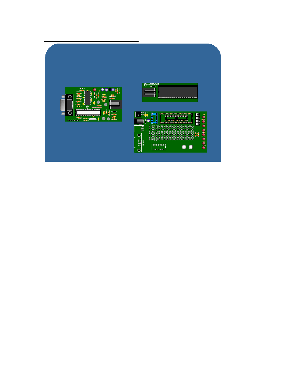
The modular design of the In-Circuit Debugger consists of the three basic components: the ICD
module, the ICD header and the ICD demo board. All of these components are included in the
ICD Evaluation Kit.
The ICD module plugs into the serial port on your PC. When instructed by MPLAB IDE, the ICD
module programs and issues debug commands to the target PIC16F87X using the ICSP protocol.
A 9-inch 6-conductor cable connects the ICD module to the ICD header. The header contains a
target PIC16F87X, a modular jack, and 28 -pin and 40-pin male DIP headers. The DIP headers
can be plugged into a target circuit board or the ICD demo board. The demo board offers LEDs,
DIP switches, a potentiometer and a prototyping area. A modular jack can be designed into the
target circuit board to accept direct connection to the ICD module.
The ICD uses the true target oscillator and target peripherals so you will see complete parallelism
of the debugger’s behavior and the real device because it is the real device that is providing that
information. There is one real -time hardware breakpoint available, which can be set at any
program memory space location. The user can also watch, examine or modify, all of the internal
file registers including general purpose registers and special function registers. You can also
download a new program to your target device.
The interface used by the ICD requires connections to only 5 pins: power, ground, MCLR and two
general purpose I/O pins, RB6 and RB7. Access to RB6 and RB7 is only required during
debugging, however, you can regain access to those pins after you are finished debugging by
reprogramming the device and disabling the debugger.
Page 10

It should be noted that the PIC16F87X devices are pin and functionally compatible with many
ROM and OTP devices. So it is possible, with care, to debug code for a ROM or OTP PIC MCU
using the appropriate PIC16F87X device.
The MPLAB ICD complete hardware development system along with the free MPLAB IDE
software provides a powerful, affordable run-time development tool.
Page 11
Slide 10: Knowledge Check #2
To write a C program for PIC18FXXX microcontrollers, all you need is:
a) Borland C++
b) MPLAB C18
c) Visual C++
d) MPLAB ICD
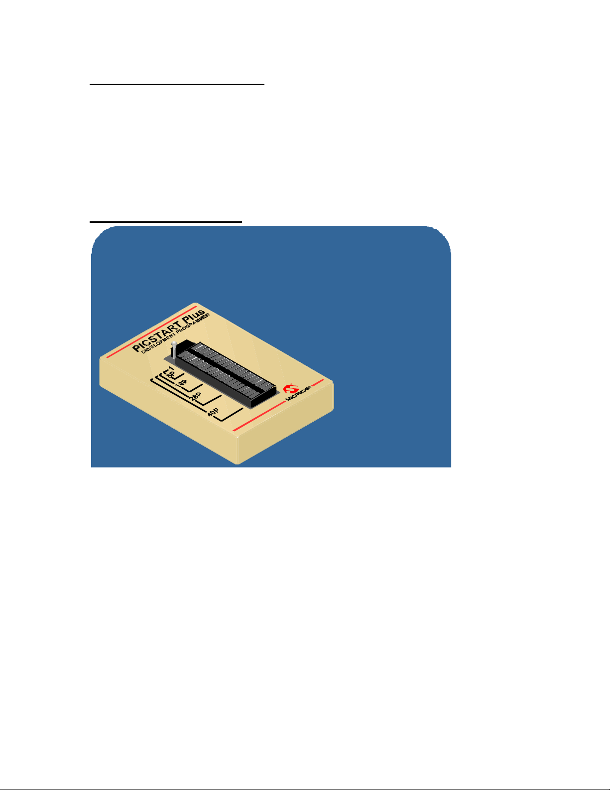
Slide 11: PICSTART® Plus
Development Tools Overview
PICSTART Plus Programmer
- Supports all devices except 16C432/433
- Interfaces to MPLAB
- Adapter sockets for PLCC packages
- Connects to PC via RS-232 port
- Firmware upgrades available from
www.microchip.com
Once you have code up and running through either the emulator, the debugger or simulator, you
will need to program your devices. The PICSTART Plus is a very convenient universal desktop
development programmer that supports all devices except the 16C432/433 devices, and also
runs under the MPLAB IDE.
It has a 40 -pin ZIF socket which supports DIP packages up to 40 pins directly. Microchip also
offers 84- and 68-pin PLCC adapters for those larger pin count surface mount devices. The
PICSTART Plus connects to a PC through a standard RS -232 serial cable.
Firmware upgrades are available www.microchip. The PICSTART Plus firmware is upgraded by
first of all, obtaining a PIC17C44 window device (available for purchase from you local Microchip
distributor), plugging it into the ZIF socket and then programming the latest firmware into that
device. Simply replacing the existing PIC17C44 with the newly programmed device enables you
to do future firmware upgrades for free at the cost of your first PIC17C44 windowed device.
Page 12
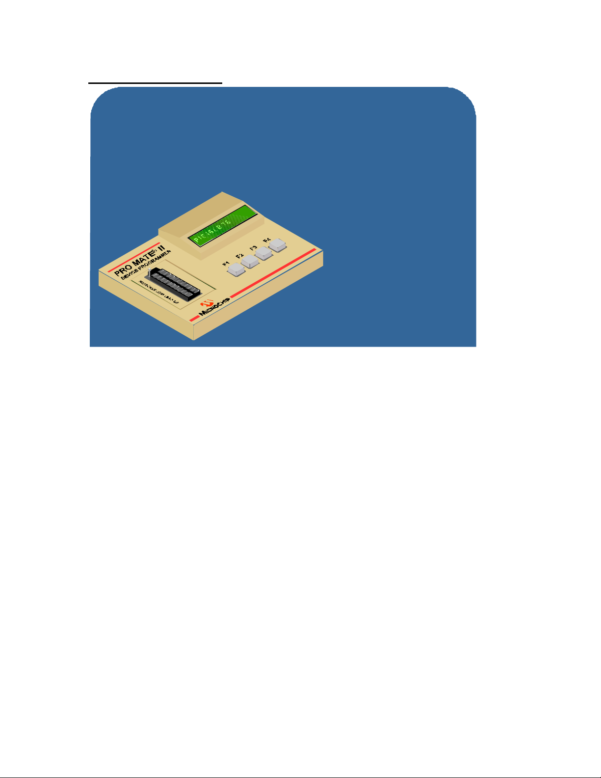
Slide 12: PRO MATE® II
Development Tools Overview
PRO MATE® II Production Programmer
- Operates in Stand-Alone mode or with MPLAB
- Interchangeable device sockets
- Supports surface mount packages
- Supports Serialized Quick Turn Programming (SQTP™)
- Environment Save and Restore
- Supports Serial EEPROMs and
Keeloq security devices
The PRO MATE II is a production quality programmer which can operate in a standalone mode or
under the MPLAB IDE.
Unlike the PICSTART Plus which is designed for DIP devices, the PRO MATE II has
interchangeable socket modules and supports all surface mount devices.
PRO MATE II also supports an In -Circuit Serial Programming module which enables you to
program a PICmicro device on your circuit board through 5 pins. Conveniently, these pins are the
same as those used for the in-circuit debugger.
In-Circuit Serial Prog ramming is convenient for late manufacturing programming or
reprogramming of devices prior to shipment. PRO MATE II has environmental save and restore
capability which allows you to save target or test voltages along with other user environment
variables. PRO MATE II supports the minimum and maximum VDD verification required by OTP
devices.
Serialized Quick Turn Programming, SQTPSM, is supported which means that the programmer
can automatically create and maintain a unique serial number that is stored in program memory
space for every device programmed. This feature allows you to program a unique serial number
in every device for applications such as remote keyless entry (RKE).
PRO MATE II also provides the capability to program Microchip’s Serial EEPROM and
KEELOQ® security devices .
Page 13

Slide 13: Knowledge Check #3
The MPLAB ICD allows the user to:
a) Program FLASH -based PICmicro microcontrollers
b) Perform Real time debug at maximum speed
c) Debug at lowest specified operating voltage
d) All of the above
Page 14

Slide 14: PICDEM™ Evaluation Boards
Development Tools Overview
PICDEM™ Evaluation Boards
PICDEM-1
- Supports 18 pin devices, 16C5x family and 17C family
PICDEM-2
- All x14 architecture devices in 28/40 pin DIP
PICDEM-3
- Supports PIC16C9XX LCD control devices
PICDEM-14A
- Supports PIC14000
PICDEM-17
- Supports PIC17C756/766
A good way to familiarize yourself with the new PICmicro MCUs is by using one of the PICDEM
evaluation boards.
The PICDEM boards differ based on the devices supported. The boards feature LEDs to indicate
the state of an I/O port pin, pushbutton switches connected to some of the I/O pins to simulate an
input pin changing, and potentiometers to test A/D features. There is a 9-pin RS -232 port
connector, which allows you to use the hardware UART featured on most PICmicro MCUs. An
oscillator socket and integrated RC oscillator support enables users to test various oscillator
frequencies.
The demo boards typically contain a programmed PIC MCU with demo firmware that customers
can use to validate that the PICDEM board is working.
The PICDEM-1 supports Microchip’s 18 -pin devices, the PIC16C5X family and the PIC17 family
of devices.
The PICDEM-2 supports all of the x14 architecture devices, including 28- and 40-pin DIP
packages.
The PICDEM-3 includes an on -board LCD display to demonstrate Microchip’s PIC16C9XX LCD
control devices.
The PICDEM-14A demonstrates the PIC14000 capabilities.
The PICDEM-17 supports PIC17C756 & PIC17C766 devices.
In additional to PICDEM boards that support specific device families, Microchip offers evaluation
kits that support various peripherals and application-specific devices, such as the PICDEM.net™.
Page 15
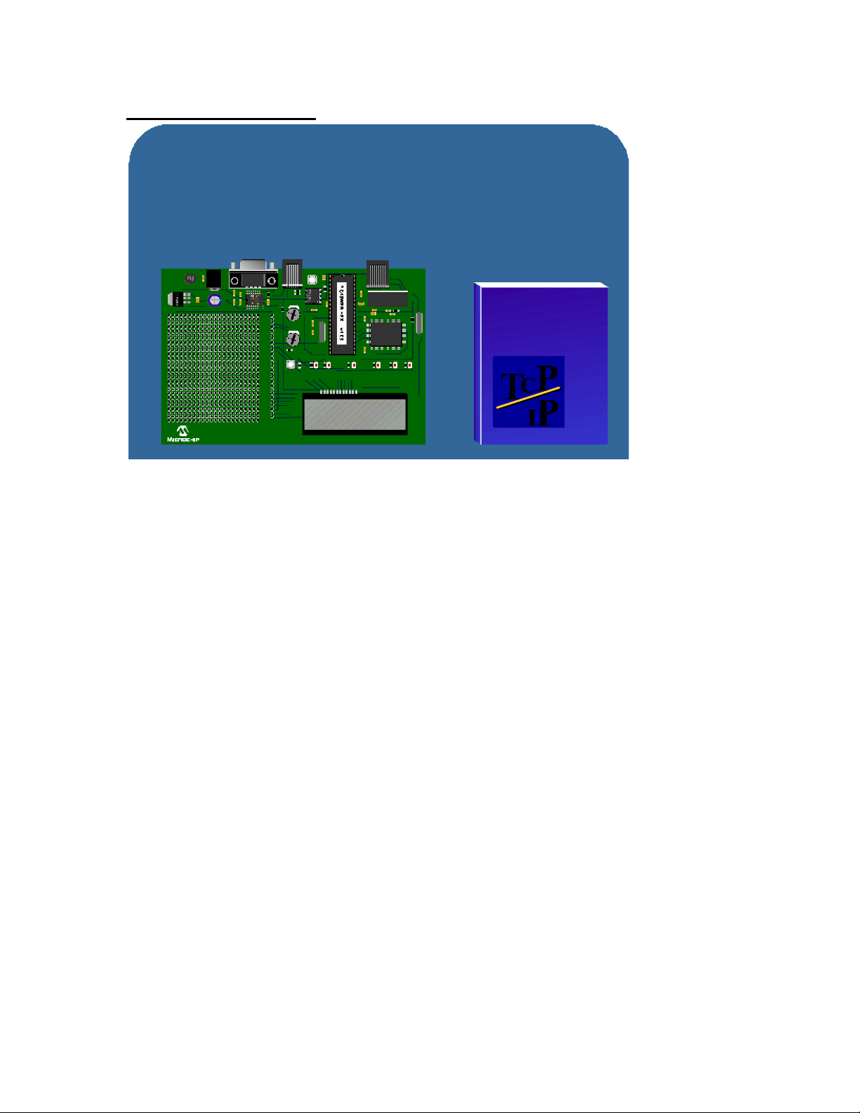
Slide 15: PICDEM.net™
Development Tools Overview
PICDEM.net™ Demo Kit
Internet and Ethernet Connectivity Design Kit
Kit includes Dev board and book
+ 9V
IN
PICDEM.net™
DEMO BOARD
MCLR
ICD
AN0
RB0
RB1
RB2
RB3
AN1
RB4
RA0
RA1
RA2
RA3
RA4
RA5
RC0
RC1
RC2
RC3
8
RB5
USER LEDs SYSTEM
RC4
RC5
RC6
RC7
RD0
RD1
RD2
RD3
RD4
RD5
RD6
RD7
FL1012
TCP/IP
LINK
XMIT
statusRXstatus
LED
status
C
T
Jeremy Bentham
LEAN
Web Servers
for
Embedded
Systems
P
I
P
The PICDEM.net™ is an Internet and Ethernet demonstration kit that is designed to show internet
connectivity capability using PIC MCUs. The complete kit includes a demonstration board with
TCP/IP stack and a book written by Jeremy Bentham which explains the basics of small TCP/IP
Internet connectivity and we b servers, along with the basics on how to implement those on a 8-bit
embedded systems.
The PICDEM.net board contains a PIC16F877, a MAC and PHY (from a company called
Realtech). The networking connection is standard RJ45 10 baseT.
The PICmicro cont ains TCP/IP stack software and a web server called, ChipWeb, both
implemented by Iosoft Ltd. This allows you to directly access the server and look at the current
state of on -board potentiometers from a remote networked PC. You can also click on buttons on
a web page to turn LEDs on and off, depicting both interactive inputs and outputs to web pages.
The PICDEM.net board supports In -Circuit Serial Programming and the ICD connector. This
allows you to update the firmware by plugging the ICD into the ICSP port and debugging the
TCP/IP stack through this port.
The board includes a prototype area for you to add some of your own circuitry.
Although PICDEM.net uses the TCP/IP stack from Iosoft Ltd., there are other stacks which are
available for PIC microcontrollers that offer various protocols including SMTP and DHCP. You
can visit the Connectivity Design Center on Microchip’s website for more information.
Page 16
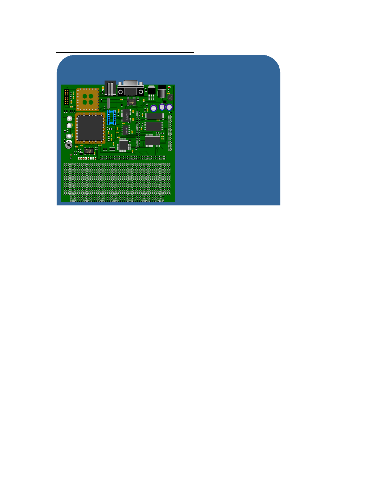
Slide 16: ROMless Development Board
Development Tools Overview
ROMless Development Board
Supports PIC18C601/801
ROMless MCUs
RESET
RB4
RB5
AGND
AVDD
12
PIC18C801
memory interfaces
- Supports 16-bit word select and
byte select memory interfaces
- 2M byes of JEDEC FLASH
memory
- 128 KB of external static RAM
- 64K I2C Serial EEPROM
- Multiplexed and de-multiplexed
The ROMless Demonstration Board supports the PIC18C601 and PIC18C801 ROMLESS
microcontrollers.
This board has both multiplexed and de-multiplexed memory interfaces and supports both16 -bit
word select and byte select memory interfaces. It contains two megabytes of JEDEC compliant
flash memory, 128 KB of external JEDEC compliant static RAM and a 64 KB I2C serial EEPROM.
There are 8 LEDs, some pushbutton switches and a potentiometer input for testing the various
I/O capabilities for these devices.
There is code included for the PC which allows you to download new hex files into static RAM
and then execute them. The user programmable PC downloader allows you to download a new
hex file to the external FLASH program area.
Page 17
Slide 17: USB Development Board
Development Tools Overview
USB Development Board
Supports PIC16C745/765 PICmicro MCUs
Powered
Addressed
Sleeping
Default
Configured
RA4
EP0-Act
EP1-Act
EP2-Act
RB0
RB0
RB1
RB1
RB2
RB2
RB3
RB3
RB4
RB4
RA0
RA0
RA1
RA1
RA2
RA2
RA3
RA3
RA4
RA4
RA5
RA5
RC0
RC0
RC1
RC1
RC2
RC2
RC3
RC3
RC4
RC4
RC5
RC5
RC6
RC6
RC7
RC7
RD0
RD0
LCD MODULE
PICDEM USB
USB
GND V+
LCD BACKLIGHT
POWER
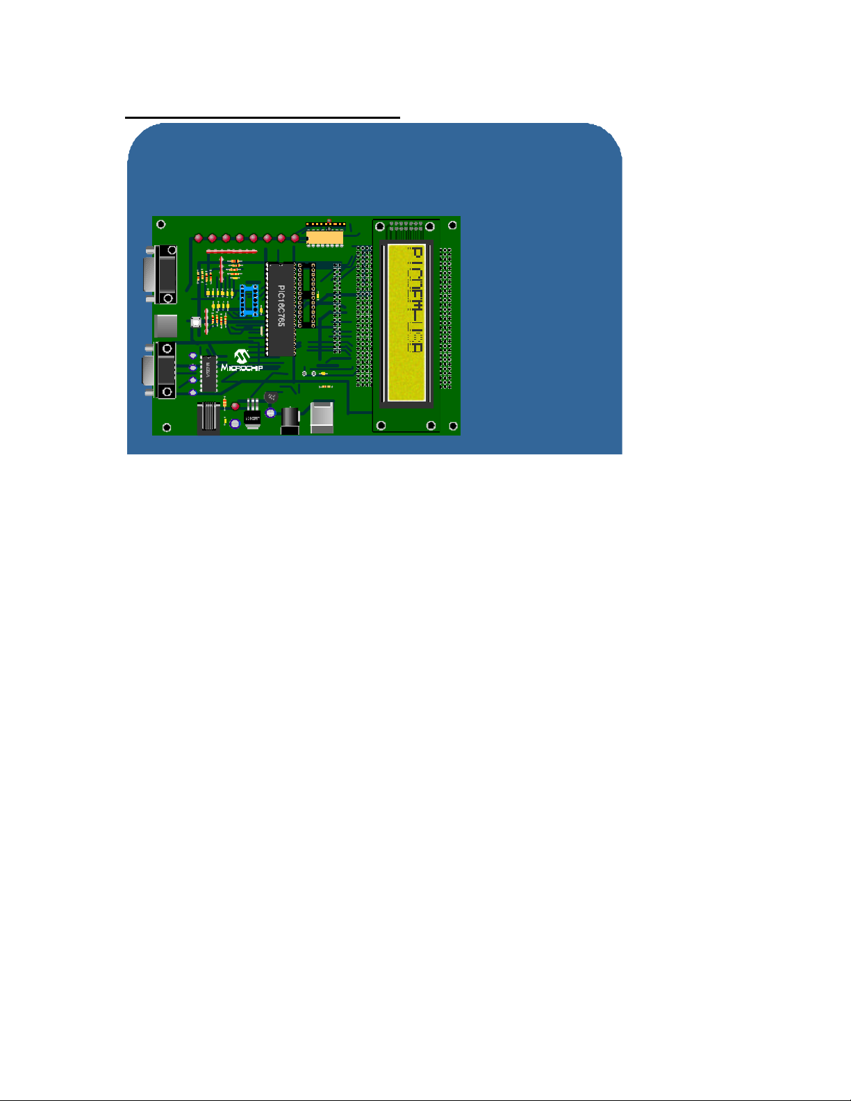
The USB Development Board supports Microchip’s PIC16C745/765 USB PIC microcontrollers.
It contains a standard USB connector which integrates the necessary 3.3 volt power supply
regulator. It also has an RS -232 serial port which connects to the PIC16C745/765 hardware
UART. A PS-2 port connects to the PICmicro MCUs general purpose I/O pins and a game port
which connects to the PICmicro’s A/D and a few general purpose I/O pins.
A prototype area and 8 LEDs are included for diagnostic purposes. There is also an LCD module
interface on the board that accepts an industry standard 2 line by 20 character LCD display.
Page 18
Slide 18: PICDEM MSC1
Development Tools Overview
PICDEM MSC1
Supports PIC17C781/782 Devices
MCLR
TP1
TP2
PIC16C781/782
Evaluation Board
+ 9V
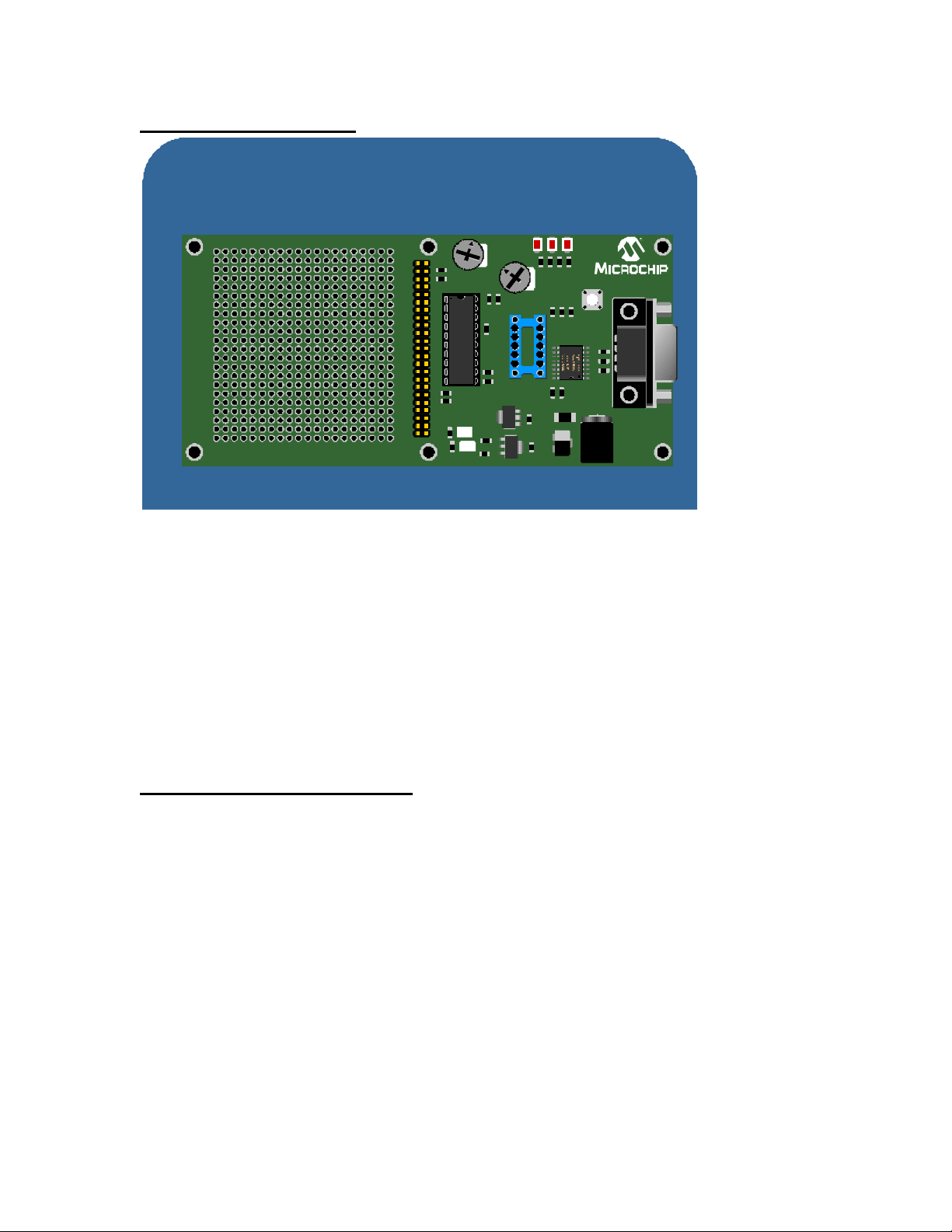
The PICDEM MSC1 is Microchip’s first mixed signal analog configurable demonstration board
which supports the PIC16C781/782 microcontrollers. This board comes with Windows based
software that allows the user to visually examine and modify all of the analog configuration
special function registers.
This will enable you to test out the switch mode power supply controller, D/A, A/D and Op Amp
features of this device without writing any PICmicro code. This is accomplished though a
software serial interface which interfaces to the PC configuration software.
As with other PICDEM boards, there is also a generous prototyping area for building additional
circuitry.
Slide 19: Knowledge Check #4
What tool does Microchip offer to assist specifically in development of real time
web pages using a PICmicro microcontroller?
a) MPLAB ICE2000
b) PICDEM.net
c) PICSTART Plus
d) MPLAB ICD
Page 19
Slide 20: MXLAB™ Mixed Signal Development Tool
Development Tools Overview
FilterLab™ Software
Windows® based software makes the design and
analysis of active low pass filters a snap!
- Shows frequency and phase response of a filter
- Shows circuit diagram
- Allows the user to choose different filter parameters and
observe the change in the filter response
FilterLab
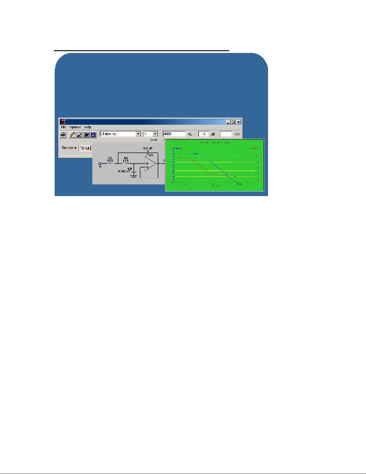
The Mixed Signal Development Tool provides support for Microchip’s standalone MCP A/D
devices and digital potentiometers. This tool consists of contains Windows based software, a
main controller board and device specific daughter boards.
The software allows you to collect A/D results and display the data in several formats, including
histogram, real time scope plot and FFT. The FFT can be useful when you want to characterize a
moderate sample rate analog sub-system, collect that data and then look at an FFT of that data
to see if you’ve got 60 or 50 Hz noise. Noise of other various primary and secondary harmonics
also show up after collecting this data an d running an FFT.
In addition to the software, the main controller/display board provides the means for acquiring
data and transmitting to a PC via a serial port. This board can also show acquired data at slow
sample rates on an LCD display. Daughter boards available separately plug into the main board
and are device specific. These include boards for A/Ds, digital pots and Op Amps. These boards
all contain a general prototyping area to enable connections to your application specific circuitry.
Page 20
Slide 21: FilterLab™ Software
Development Tools Overview
FilterLab™ Software
Windows® based software makes the design and
analysis of active low pass filters a snap!
- Shows frequency and phase response of a filter
- Shows circuit diagram
- Allows the user to choose different filter parameters and
observe the change in the filter response
FilterLab
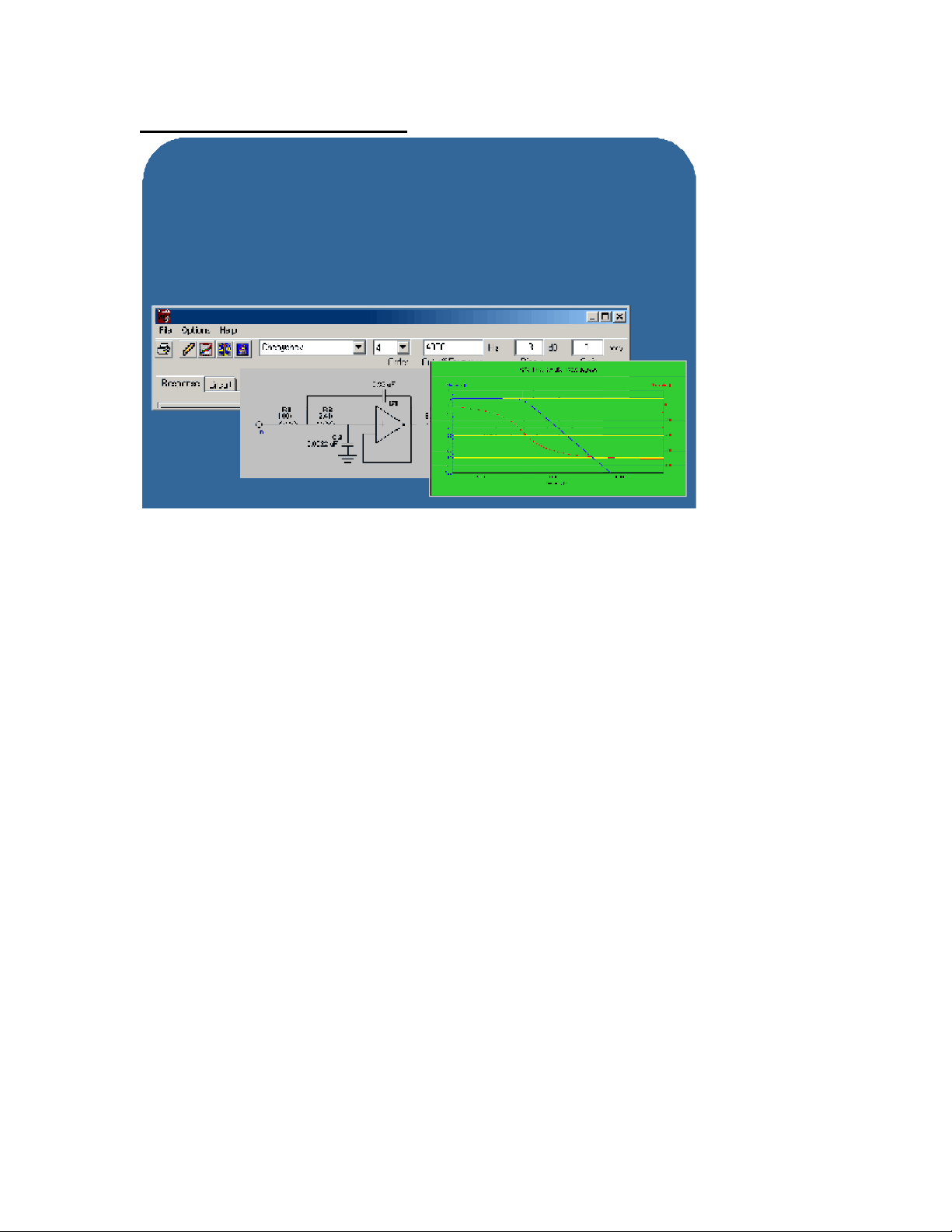
FilterLab is an active filter design tool, which greatly simplifies the job of designing low -pass filters
which are required for anti-aliasing in nearly all analog sampling systems.
The program allows the user to specify the type of filter that you want to use, such as Chebyshev,
Bessel or Butterworth, and then specify the order of the filter, desired cut -off frequency, ripple and
gain. FilterLab will then generate a schematic and show you all of the R and C values for the lowpass filter that was generated. It will also show the frequency and phase response of the filter,
and can even generate a spice model.
This tool is available free and can greatly reduce the amount of time required to design active low
pass filters.
Page 21
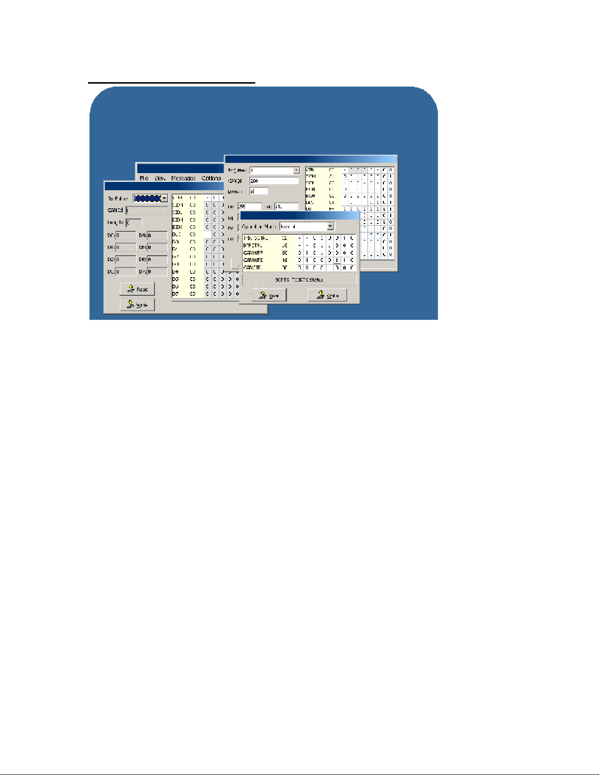
Slide 22: CAN Developer’s Kit
Development Tools Overview
CAN Developer's Kit
Supports the MCP2510 Stand-alone CAN controller
- Windows based software to watch/modify CAN registers
- Demo board provides access to two complete CAN nodes
CANking for Windows
MCP2510 Receive Buffer
MCP2510 Transmit Buffer
MCP Configuration
The MCP2510 CAN Developer’s Kit enables a user to evaluate and test systems that implement
the MCP2510 standalone CAN controller.
The kit comes with an evaluation board that communicates to a PC via the parallel port.
Windows based software allows you to set up and read all of the MCP2510 CAN registers. This
kit also contains a high level protocol called CAN Kingdom that enables you to send and receive
messages and validate the operation of a CAN enabled system.
There is a second node on the CAN bus which consists of another MCP2510 and a PIC16F876
that are connected together via the SPI port. This enables the user to write PICmicro firmware
which communicates to the MCP2510 in order to send and receive CAN messages.
This board effectively creates a 2-node CAN bus that can be used to develop and troubleshoot
CAN communication firmware and hardware. The board also contains a prototype area for
experimenting with additional circuits or adding additional nodes to the bus.
Page 22
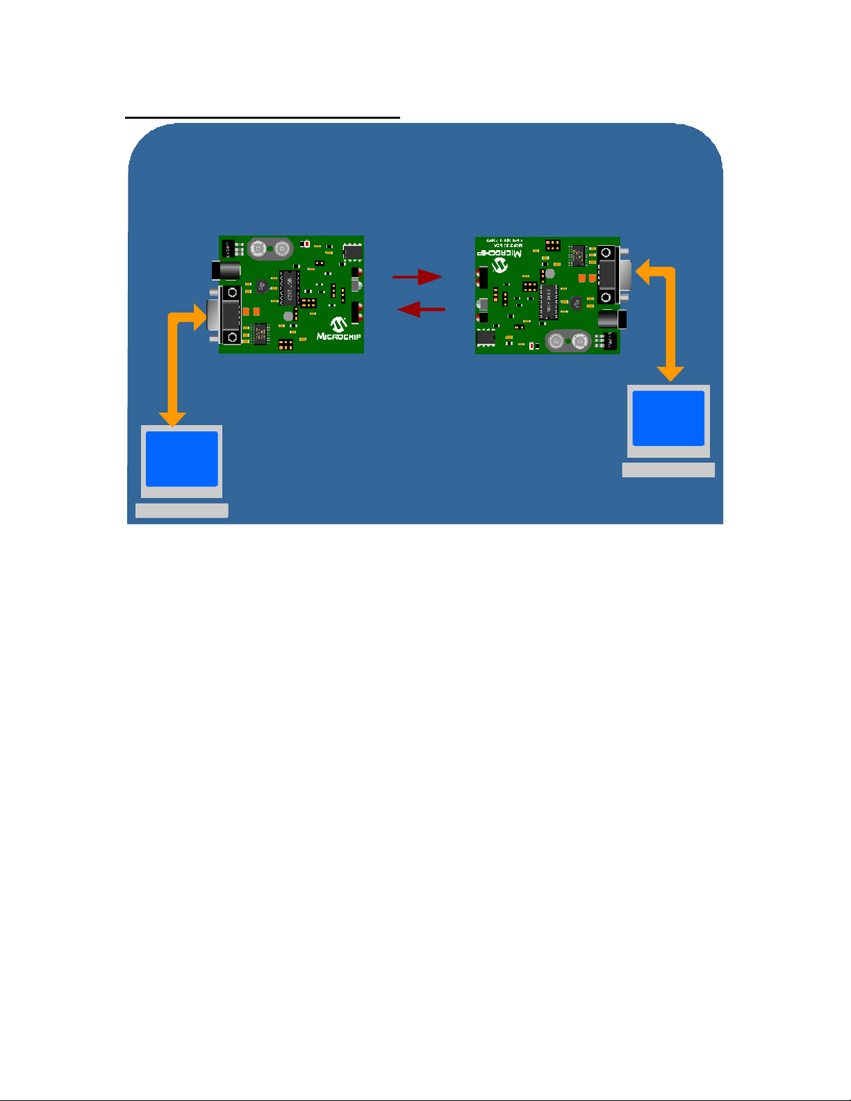
Slide 23: Infrared Development Kit
Development Tools Overview
Infrared Development Kit
Supports MCP2120/2150 IrDA devices
- Kit includes MCP2120 boards that enable the user to
set up an IR communication link between 2 computers
MCP2120 IrDA
Developers Board
Microchip’s MCP2120 and MCP2150 Infrared Development Kit can be used to experiment with
data communication via an infrared link. This kit contains two MCP2120 developer’s boards and
one MCP2150 developer’s board.
The MCP2120 developer’s boards contain both integrated and discrete solutions of the IR
transceiver interface logic, which is selectable by the user.
The host controller interface on the board connects both to a serial port and a header connector.
When connected to a PC serial port, the MCP2120 board converts RS -232 data to IR and vice
versa. Two boards are included so 2 PCs can be used to communicate to one another via IR.
The MCP2150 developer’s board implements an IrDA stack for IRCOMM, 9-wire “cooked” service
class applications. This enables the MCP2150 to communicate with a PDA or PC. The PC
requires an IR driver set up as a virtual serial port that a terminal emulation program can connect
to. A PDA requires IrDA standard interface which a terminal emulation program can connect to.
The MCP2150 replaces a wired serial connection with an IR serial connection which allows data
to be sent back and forth.
RF Link
Page 23
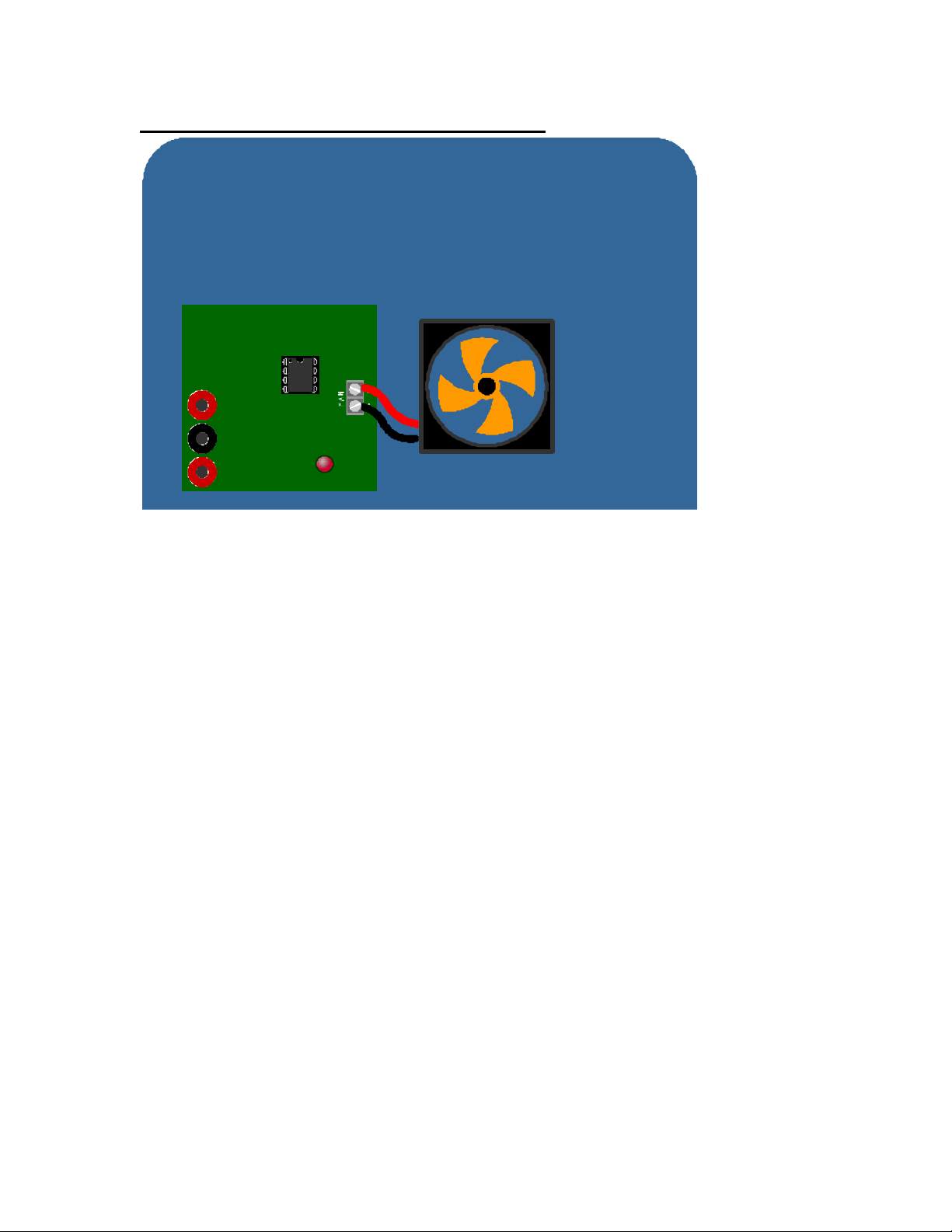
Slide 24: Fan Controller Development Boards
Development Tools Overview
Fan Controller Development Boards
Support for TC64x and TC65x Devices
- Controllers for DC brushless fans
- Locked rotor detection
- Set On/Off trigger points
TC64x/65x
Fan Controller
VFAN
GDN
VDD
FAULT
There are also development boards available for Microchip’s TC64x and TC65x PWM Fan
Controller devices. These boards allow the connection of a DC brushless fan to test the
automatic locked rot or detection, and also to trigger the fan to turn on and off at various
temperature threshold points.
Page 24
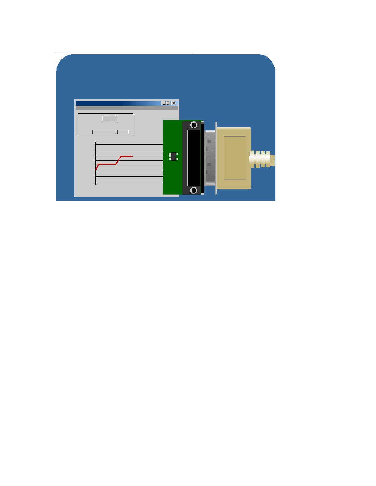
Slide 25: Thermal Sensor Demo Board
Development Tools Overview
TC74 Thermal Sensor Demo Board
Connects to PC via a standard Parallel cable
Easy to use Windows™ based software allows user to track
temperature and display in different formats
TC74 Serial Temperature Sensor Software
File LPT Port SMB Address Help
Board Power
(°C)
On
Temperature Register
00010101 +21
26
25
24
23
22
21
20
19
Sample Number
Parallel
Connector
TC74
Temperature
Sensor
The TC74 demo board demonstrates the simple to use TC74 Temperature sensor IC. This is a
very small demo board that connects directly to the parallel port on a PC. Software included
allows the user to acquire temperature data in in time increments ranging from seconds to hours.
Data acquired can be displayed in a number of different ways depending on the application.
Page 25
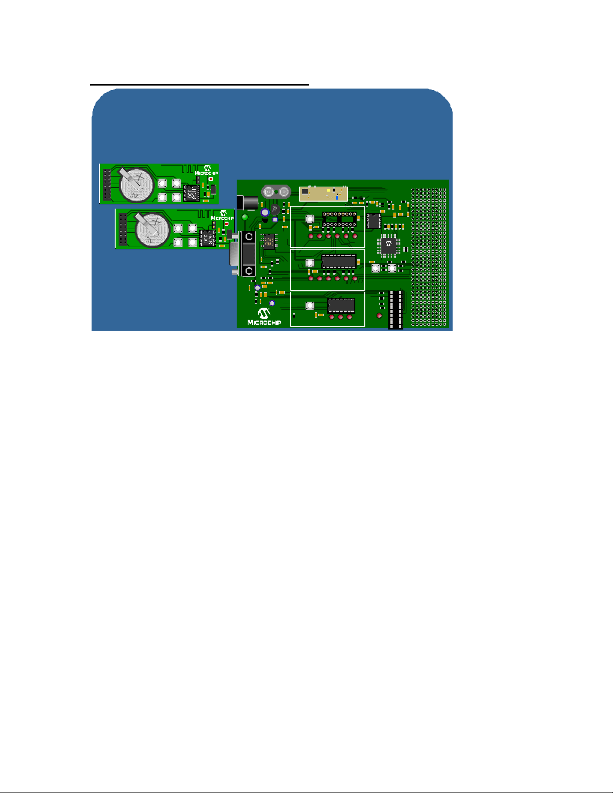
Slide 26: The KEELOQ® Evaluation Kit
Development Tools Overview
KEELOQ® Evaluation Kit
Supports HCS 500/512/515 Decoders and HCS300 Encoders
- Kit includes 2 transmitters and decoder/programmer board
- Allows demonstration/evaluation of RF code hopping technology
KEELOQ
Transmitter
®
KEELOQ
DECODER/PROGRAMMER
BOARD
KEELOQ
Transmitter
PWR
SOFTWARE DECODER
LEARN
LEARN
S0 S1 S2 S3 FUNC
OUT
HCS512 DECODER
LEARN
LEARN
S0 S1 S2 S3 FUNC
OUT
HCS515 DECODER
LEARN
LEARN
OUT
MCP 3204
S0 S1
OK
16F877
RESETBOOT
PROGRAMMING
OK
PROGRAM
MODRE
SOCKET
The KEELOQ Evaluation Kit demonstrates the HCS515 and HCS500 decoders. It also contains
a PIC16F877 which can be used to program any of the KEELOQ encoders and decoders such as
HCS300 and HCS500 series devices. There are also sockets for an RF receiver which can also
be used to demonstrate wireless transmission.
The kit comes with two independent RF transmitters which use HCS300 series encoders. These
transmitters can demonstrate wireless code hopping capabilities. This kit can be used as a
universal KEELOQ programmer, as well as a demonstration tool for transponder and standard
encoder wireless operation.
Page 26
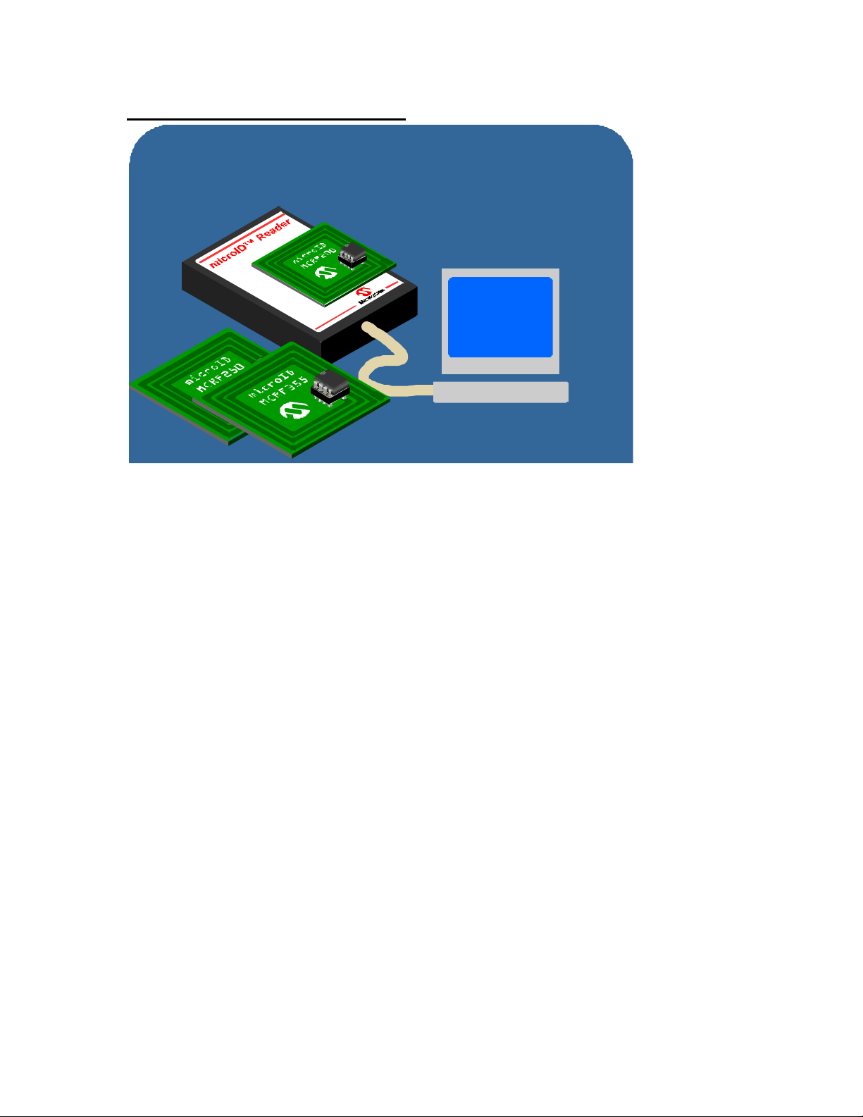
Slide 27: microID™ Developer’s Kit
Development Tools Overview
microID™ RFID Tag Developer's Kit
Developer kit support available for all microID products
Kit includes reader/programmer, software and sample tags
microID Data
7E4F4F0DCC
The microID Developer’s Kit includes a RFID reader and writer which supports the MCRF200,
MCRF250 and MCRF355 anti-collision devices.
The complete design for these RF readers is included, along with schematics, source code and
various reference design material. This kit enables an engineer who is new to RFID technology
to investigate a working design, and evaluate it’s performance.
These kits also contain a wireless RFID device programmer to support some of the latest
contactless programmable RFID products.
Page 27
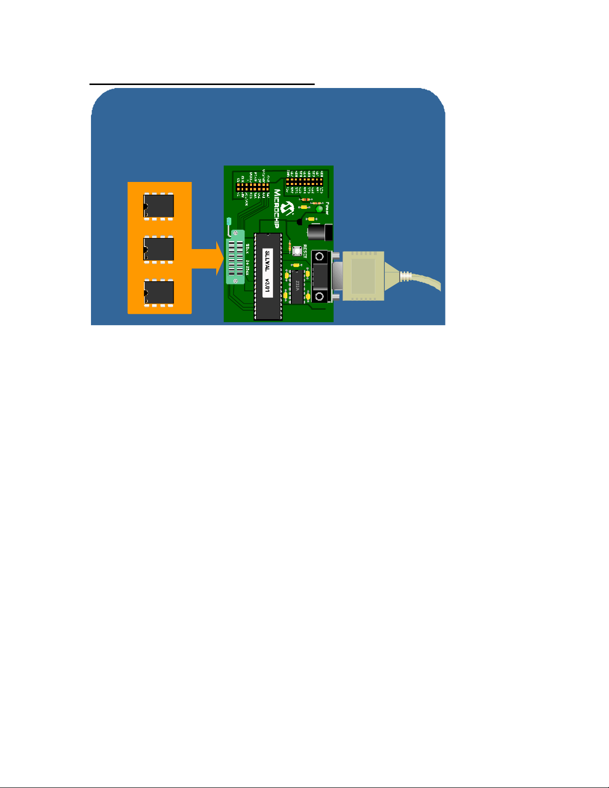
Slide 28: Serial EEPROM Designer’s Kit
Development Tools Overview
Serial EEPROM Designer's Kit (SEEVAL)
Reads and writes to any Microchip serial EEPROM
Windows based software
- Endurance testing
- Simple serial port connection
I2C™
24xxx
SPI™
25xxx
Microwire
®
93xxx
The Serial EEPROM Designer’s Kit can be used to read or program any of our serial EEPROM
devices. It can also be used to test the endurance of a device by exec uting a loop where it
continually writes data to the device and then validates the data after each cycle in the loop.
This kit comes with Windows based software and connects to the PC via the serial port. A ZIF
socket on the board allows support for I2C™, SPI™ and Microwire® Serial EEPROM devices.
Page 28
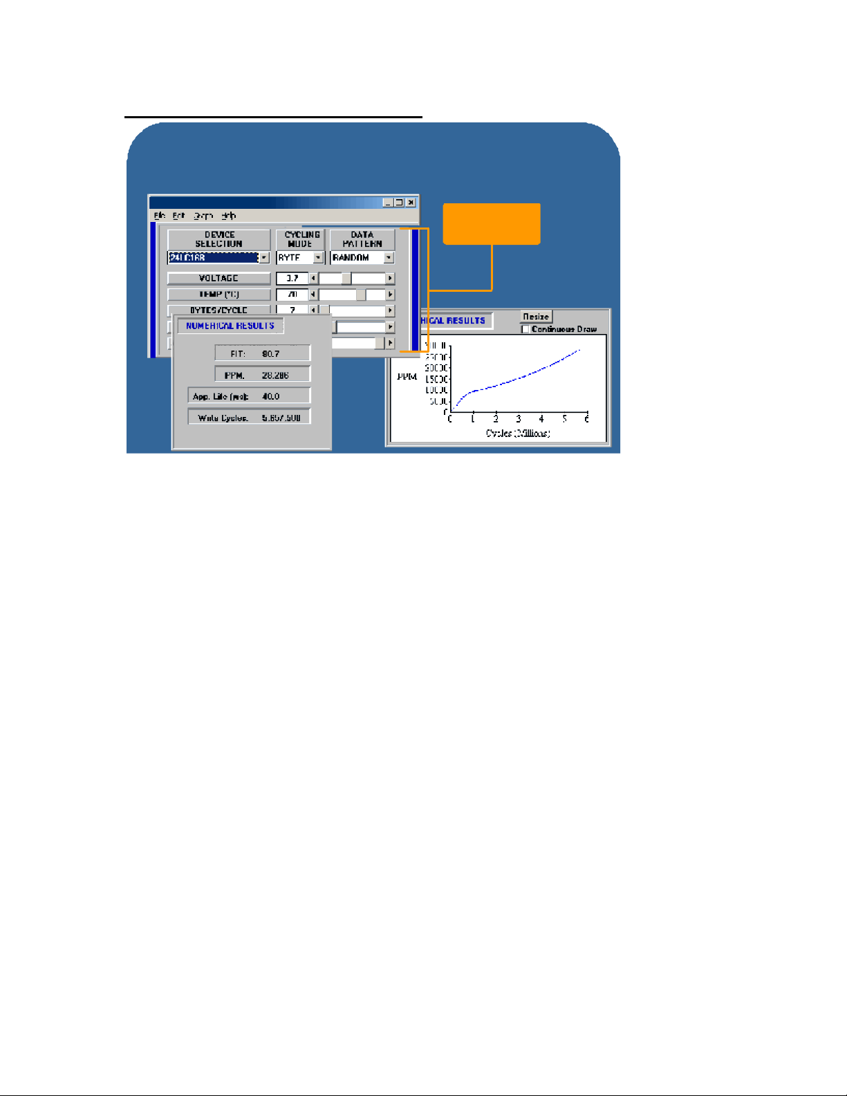
Slide 29: Total Endurance™ Software
Development Tools Overview
Total Endurance™ Software
Windows based software will predict the life of an EEPROM
product based on system parameters given by the user
TOTAL ENDURANCE
Enter your
application
parameters here
The Total Endurance software can be used to predict serial EEPROM endurance based on
application specific requirements. This software allows the user to enter application details such
as voltage, operating temperature, number of erase write cycles per day. The software will then
predict the EEPROM endurance throughout the expected application lifetime.
The Total Endurance software is Windows based and can be downloaded free from
www.microchip.com.
Page 29

Slide 30: Third Party Development Tools
Development Tools Overview
Third Party Development Tools
Third Party Partners provide
- C Compilers
- Programmers
- Assemblers
- Gang programmers
- Cross Assemblers
- Educational tools
- Development boards
- Assemblers
- Project Consulting
Download the Third Party Guide from www.microchip.com
There are many Third Parties who support the popular PICmicro® architecture. These Third Party
companies offer everything from assemblers, linkers, programmers, C compilers, real time
operating systems, TCP/IP stacks and other development tools.
You can visit the Microchip website and download the Third Party reference guide which offers a
variety of interconnect and gang prog rammer solutions.
This guide also contains a listing of more than 250 worldwide design consultants who are very
familiar with the PICmicro architecture and can provide consulting resources for both hardware
and software implementations using PICmicro devices.
Slide 31: Knowledge Check #5
Which of the following development tools provides the means for acquiring data
from an A/D and displaying the data as an FFT?
a) FilterLab
b) USB Developer Kit
c) FTTLab
d) MXLAB
Page 30
Slide 32: Closing Slide
Development Tools Overview
Closing Slide
Development Tools Overview
This concludes the Development Tools Overview course. We hope you found this presentation
interesting and worthwhile. If you have comments about this presentation or any other topic
concerning Microchip’s eLearning Program, you can send your comments by clicking on the
“Feedback” link on the left side of this screen.
 Loading...