

Page 1
LCDWIKI 2.0inch 4-line-SPI IPS Module MSP2008 User Manual CR2020-MI7011
2.0inch 4-line-SPI IPS Module MSP2008
User Manual
www.lcdwiki.com 1 / 21 Rev1.0
Page 2
LCDWIKI 2.0inch 4-line-SPI IPS Module MSP2008 User Manual CR2020-MI7011
Name
Description
Display Color
RGB 65K color
SKU
MSP2008
Screen Size
2.0(inch)
Type
TFT
Driver IC
ST7789
Resolution
320*240 (Pixel)
Module Interface
4-line SPI interface
Active Area
30.60x40.80 (mm)
Touch Screen Type
have no touch screen
Touch IC
have no touch IC
Module PCB Size
36.48x61.12(mm)
Product Description
This product is a 2.0inch IPS display module,it has a resolution of 320x240.it uses a
4-wire SPI communication method and the inner IC is ST7789.The module contains an
LCD display and PCB backboard.
Product Features
2.0-inch color screen,support 65K color display,display rich colors
320X240 resolution, clear display
Large viewing angle(full angle),display color undistorted.
Using the 4-line-SPI serial bus, it only takes a few IOs to illuminate the display
Provide a rich STM32, C51, Arduino and MSP430 sample program
Military-grade process standards, long-term stable work
Provide underlying driver technical support
Product Parameters
www.lcdwiki.com 2 / 21 Rev1.0
Page 3
LCDWIKI 2.0inch 4-line-SPI IPS Module MSP2008 User Manual CR2020-MI7011
Angle of view
all angle
Operating Temperature
-10℃~60℃
Storage Temperature
-20℃~70℃
Operating Voltage
3.3V
Power Consumption
TBD
Product Weight(With packaging)
15(g)
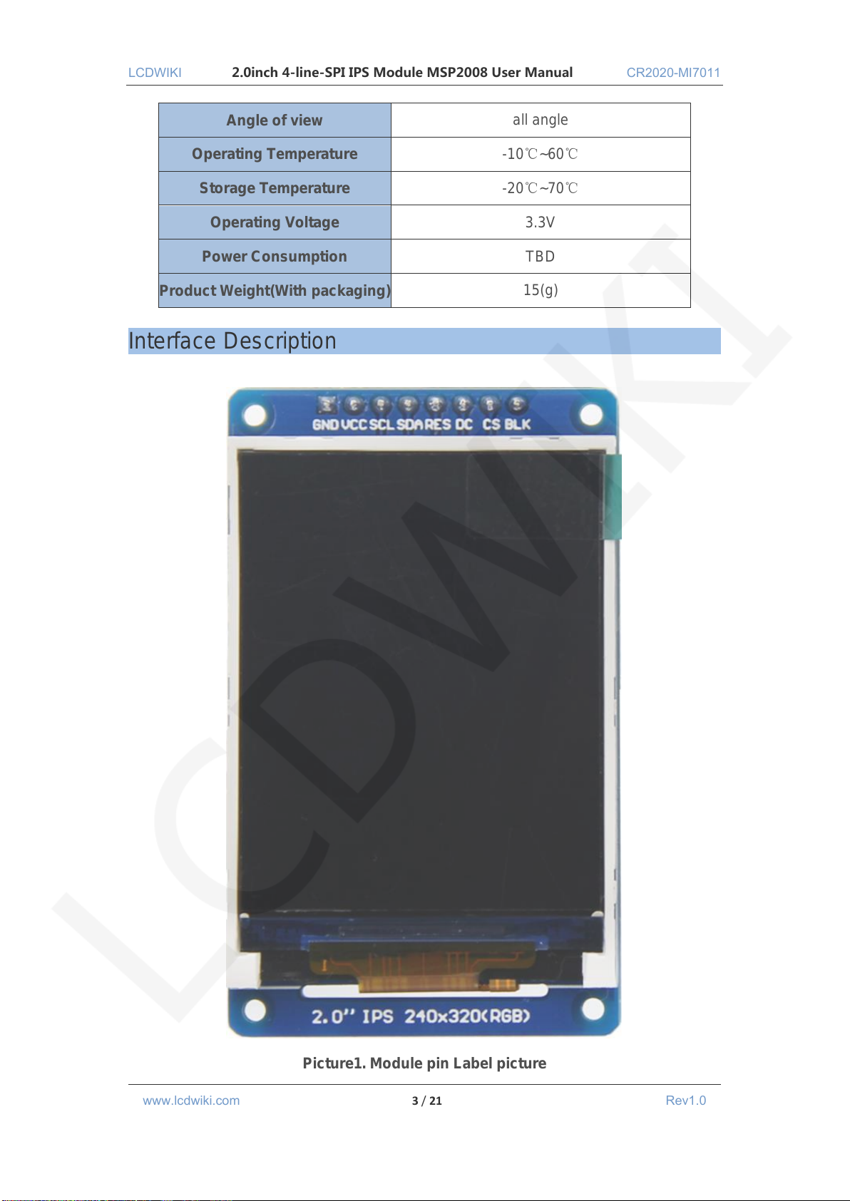
Interface Description
www.lcdwiki.com 3 / 21 Rev1.0
Picture1. Module pin Label picture
Page 4
LCDWIKI 2.0inch 4-line-SPI IPS Module MSP2008 User Manual CR2020-MI7011
Number
Module Pin
Pin Description
1
GND
LCD Power ground
2
VCC
LCD power supply is positive (Connect 5V on arduino MCU
and 3.3V on other MCU)
3
SCL
LCD SPI bus clock signal
4
SDA
LCD SPI bus write data signal
5
RES
LCD reset control signal(Low level reset)
6
DC
LCD register / data selection control signal(Low level:
register, high level: data)
7
CS
LCD chip select control signal (low level enable)
8
BLK
LCD backlight control signal (high level lighting, if you do not
need control, please connect 3.3V)
important:
1. The following pin numbers 1~8 refer to the module pin numbers of
our company with PCB backplane. If you are buying a bare screen,
please refer to the pin definition of the bare screen specification,
refer to the wiring according to the signal type instead of directly
according to the following. The module pin number is used for
wiring. For example: DC is 6 feet on our module. It may be x pin on
different size bare screen.
2. About VCC supply voltage: The IPS display module can only be
connected to 3.3V.
3. About backlight voltage: The module with PCB backplane has
integrated triode backlight control circuit, only need to input high
level or PWM wave on BL pin to backlight. If you are buying a bare
screen, the LEDAx is connected to 3.0V-3.3V, and the LEDKx can be
grounded.
www.lcdwiki.com 4 / 21 Rev1.0
Page 5
LCDWIKI 2.0inch 4-line-SPI IPS Module MSP2008 User Manual CR2020-MI7011
Hardware Configuration
The LCD module hardware circuit comprises two parts: an LCD display control circuit
and a backlight control circuit.
The LCD display control circuit is used to control the pins of the LCD, including
control pins and data transfer pins.
The backlight control circuit is used to control the backlight to be on and off. Of course,
if the backlight is not required to be be on and off, can be directly connected to the 3.3V
power supply.
working principle
1. Introduction to ST7789 Controller
The ST7789 controller supports a maximum resolution of 240*320 and a 172800-byte
GRAM. It also supports 8-bit, 9-bit, 16-bit, and 18-bit parallel port data buses. It also
supports 3-wire and 4-wire SPI serial ports. Since parallel control requires a large number
of IO ports, the most common one is SPI serial port control. The ST7789 also supports
65K, 262K RGB color display, display color is very rich, while supporting rotating display
and scroll display and video playback, display in a variety of ways.
The ST7789 controller uses 16bit (RGB565) to control a pixel display, so it can
display up to 65K colors per pixel. The pixel address setting is performed in the order of
rows and columns, and the incrementing and decreasing direction is determined by the
scanning mode. The ST7789 display method is performed by setting the address and then
setting the color value.
2. Introduction to SPI communication protocol
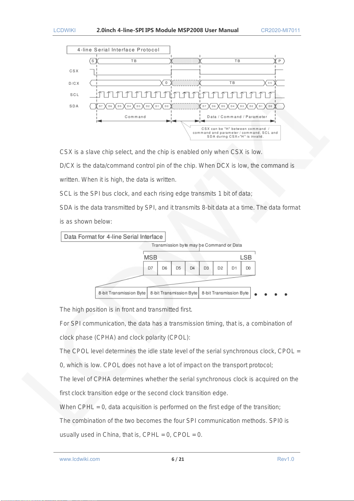
The 4-wire SPI bus write mode timing is shown in the following figure:
www.lcdwiki.com 5 / 21 Rev1.0
Page 6
LCDWIKI 2.0inch 4-line-SPI IPS Module MSP2008 User Manual CR2020-MI7011
CSX is a slave chip select, and the chip is enabled only when CSX is low.
D/CX is the data/command control pin of the chip. When DCX is low, the command is
written. When it is high, the data is written.
SCL is the SPI bus clock, and each rising edge transmits 1 bit of data;
SDA is the data transmitted by SPI, and it transmits 8-bit data at a time. The data format
is as shown below:
The high position is in front and transmitted first.
For SPI communication, the data has a transmission timing, that is, a combination of
clock phase (CPHA) and clock polarity (CPOL):
The CPOL level determines the idle state level of the serial synchronous clock, CPOL =
0, which is low. CPOL does not have a lot of impact on the transport protocol;
The level of CPHA determines whether the serial synchronous clock is acquired on the
first clock transition edge or the second clock transition edge.
When CPHL = 0, data acquisition is performed on the first edge of the transition;
The combination of the two becomes the four SPI communication methods. SPI0 is
usually used in China, that is, CPHL = 0, CPOL = 0.
www.lcdwiki.com 6 / 21 Rev1.0
Page 7
LCDWIKI 2.0inch 4-line-SPI IPS Module MSP2008 User Manual CR2020-MI7011
STM32F103RCT6 microcontroller test program wiring
instructions
Number
Module Pin
Corresponding to MiniSTM32
development board wiring pin
1
GND
GND
2
VCC
3.3V
3
SCL
PB13
4
SDA
PB15
5
RES
PB12
6
DC
PB10
7
CS
PB11
8
BLK
PB9
STM32F103ZET6 microcontroller test program wiring
instructions
Number
Module Pin
Corresponding to Elite STM32
development board wiring pin
1
GND
GND
2
VCC
3.3V
3
SCL
PB13
4
SDA
PB15
5
RES
PB12
6
DC
PB10
7
CS
PB11
8
BLK
PB9
Instructions for use
1. STM32 instructions
Wiring instructions:
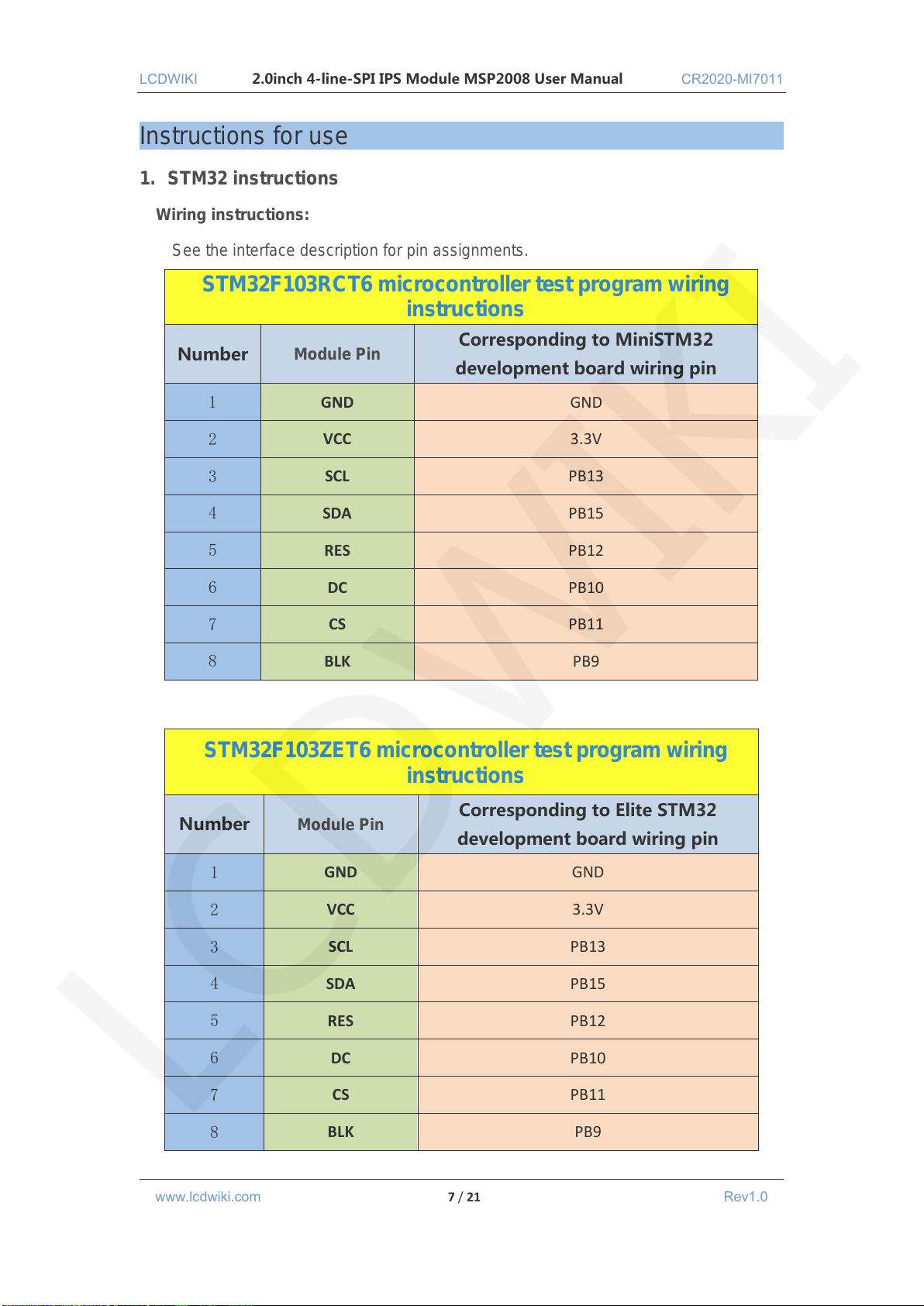
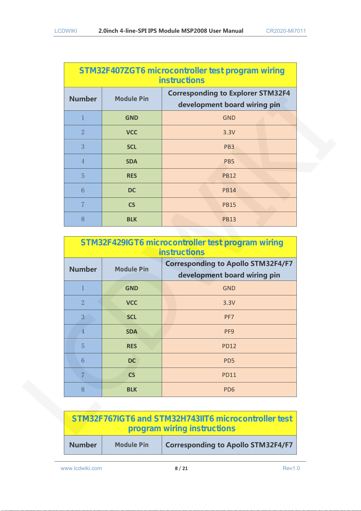
See the interface description for pin assignments.
www.lcdwiki.com 7 / 21 Rev1.0
Page 8
LCDWIKI 2.0inch 4-line-SPI IPS Module MSP2008 User Manual CR2020-MI7011
STM32F407ZGT6 microcontroller test program wiring
instructions
Number
Module Pin
Corresponding to Explorer STM32F4
development board wiring pin
1
GND
GND
2
VCC
3.3V
3
SCL
PB3
4
SDA
PB5
5
RES
PB12
6
DC
PB14
7
CS
PB15
8
BLK
PB13
STM32F429IGT6 microcontroller test program wiring
instructions
Number
Module Pin
Corresponding to Apollo STM32F4/F7
development board wiring pin
1
GND
GND
2
VCC
3.3V
3
SCL
PF7
4
SDA
PF9
5
RES
PD12
6
DC
PD5
7
CS
PD11
8
BLK
PD6
STM32F767IGT6 and STM32H743IIT6 microcontroller test
program wiring instructions
Number
Module Pin
Corresponding to Apollo STM32F4/F7
www.lcdwiki.com 8 / 21 Rev1.0
Page 9
LCDWIKI 2.0inch 4-line-SPI IPS Module MSP2008 User Manual CR2020-MI7011
development board wiring pin
1
GND
GND
2
VCC
3.3V
3
SCL
PB13
4
SDA
PB15
5
RES
PD12
6
DC
PD5
7
CS
PD11
8
BLK
PD6
Operating Steps:
A. Connect the IPS module and the STM32 MCU according to the above wiring
instructions, and power on;
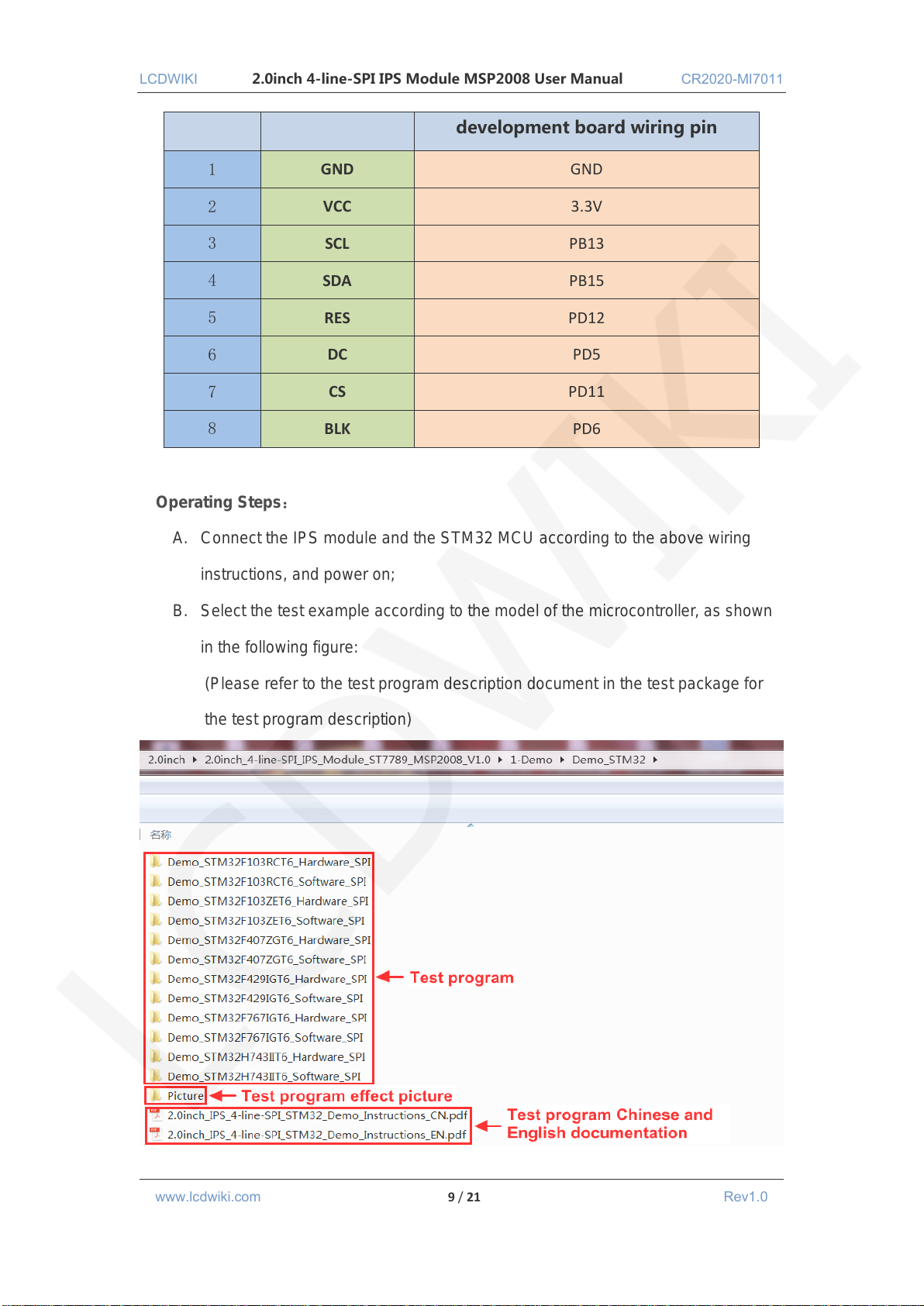
B. Select the test example according to the model of the microcontroller, as shown
in the following figure:
(Please refer to the test program description document in the test package for
the test program description)
www.lcdwiki.com 9 / 21 Rev1.0
Page 10
LCDWIKI 2.0inch 4-line-SPI IPS Module MSP2008 User Manual CR2020-MI7011
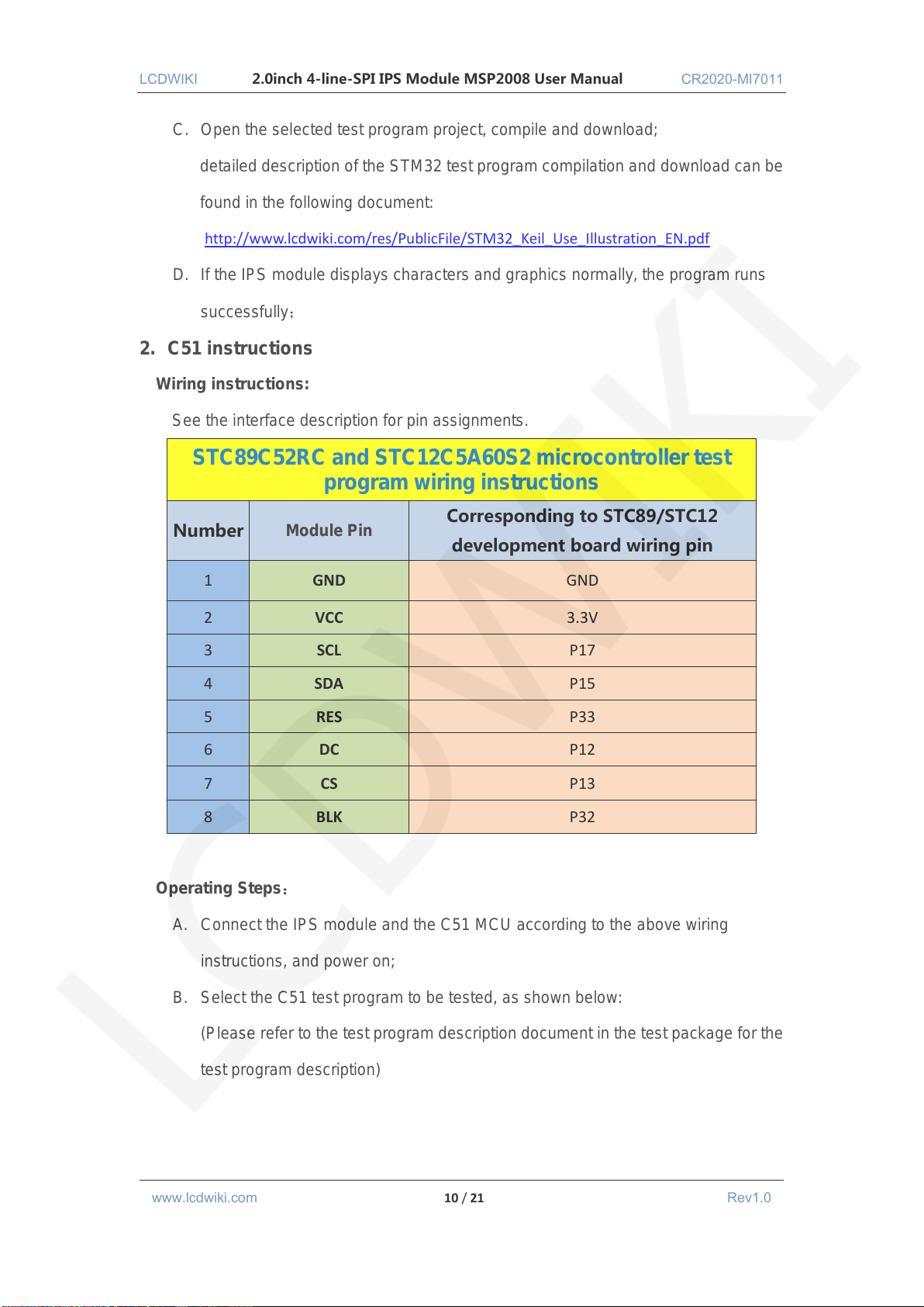
STC89C52RC and STC12C5A60S2 microcontroller test
program wiring instructions
Number
Module Pin
Corresponding to STC89/STC12
development board wiring pin
1
GND
GND
2
VCC
3.3V
3
SCL
P17
4
SDA
P15
5
RES
P33
6
DC
P12
7
CS
P13
8
BLK
P32
C. Open the selected test program project, compile and download;
detailed description of the STM32 test program compilation and download can be
found in the following document:
http://www.lcdwiki.com/res/PublicFile/STM32_Keil_Use_Illustration_EN.pdf
D. If the IPS module displays characters and graphics normally, the program runs
successfully;
2. C51 instructions
Wiring instructions:
See the interface description for pin assignments.
Operating Steps:
A. Connect the IPS module and the C51 MCU according to the above wiring
instructions, and power on;
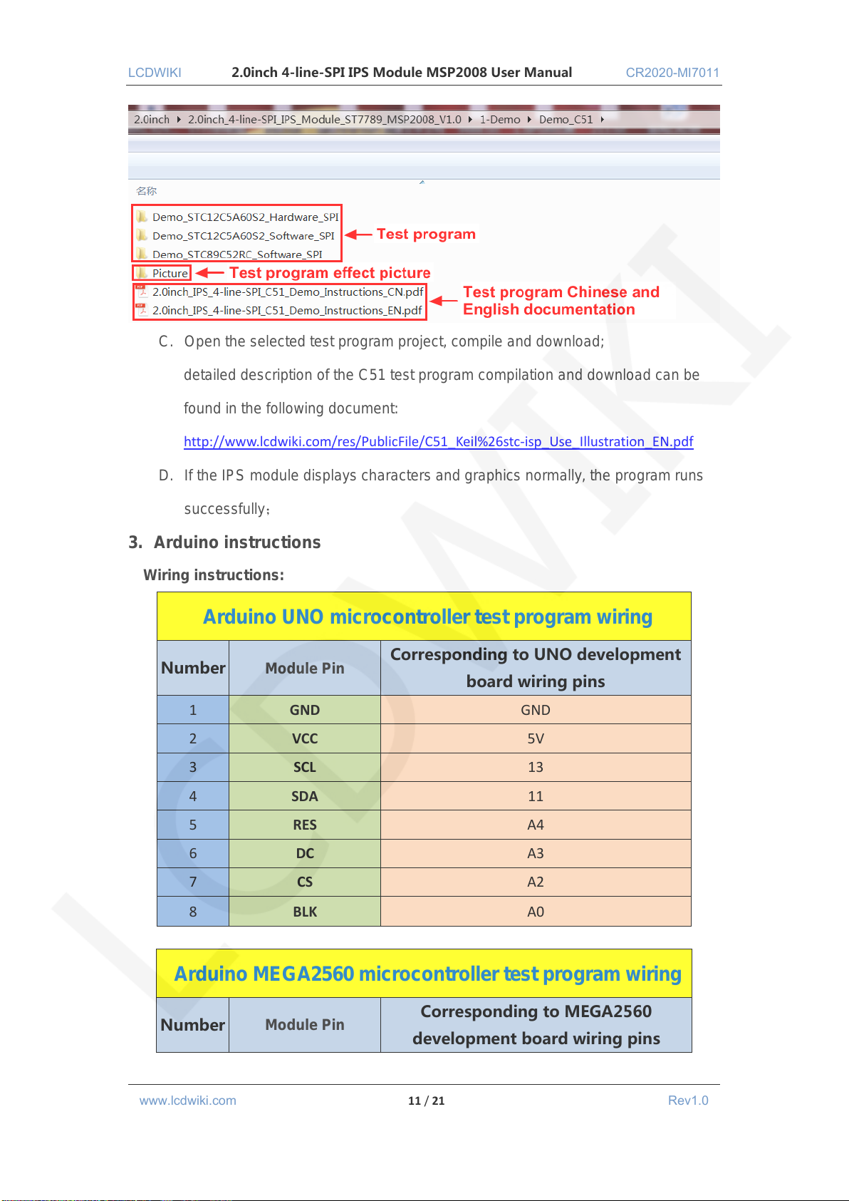
B. Select the C51 test program to be tested, as shown below:
(Please refer to the test program description document in the test package for the
test program description)
www.lcdwiki.com 10 / 21 Rev1.0
Page 11
LCDWIKI 2.0inch 4-line-SPI IPS Module MSP2008 User Manual CR2020-MI7011
Arduino UNO microcontroller test program wiring
Number
Module Pin
Corresponding to UNO development
board wiring pins
1
GND
GND
2
VCC
5V
3
SCL
13
4
SDA
11
5
RES
A4
6
DC
A3
7
CS
A2
8
BLK
A0
Arduino MEGA2560 microcontroller test program wiring
Number
Module Pin
Corresponding to MEGA2560
development board wiring pins
C. Open the selected test program project, compile and download;
detailed description of the C51 test program compilation and download can be
found in the following document:
http://www.lcdwiki.com/res/PublicFile/C51_Keil%26stc-isp_Use_Illustration_EN.pdf
D. If the IPS module displays characters and graphics normally, the program runs
successfully;
3. Arduino instructions
Wiring instructions:
www.lcdwiki.com 11 / 21 Rev1.0
Page 12
LCDWIKI 2.0inch 4-line-SPI IPS Module MSP2008 User Manual CR2020-MI7011
1
GND
GND
2
VCC
5V
3
SCL
52
4
SDA
51
5
RES
A4
6
DC
A3
7
CS
A2
8
BLK
A0
Operating Steps:
A. Connect the LCD module and the Arduino MCU according to the above wiring
instructions, and power on;
B. Copy the dependent libraries in the Install libraries directory of the test package to
the libraries folder of the Arduino project directory (the default Arduino project
directory is C:\Users\Administrator\ Documents\Arduino\libraries.if you do not
need to depend on the libraries, you do not need to copy them);
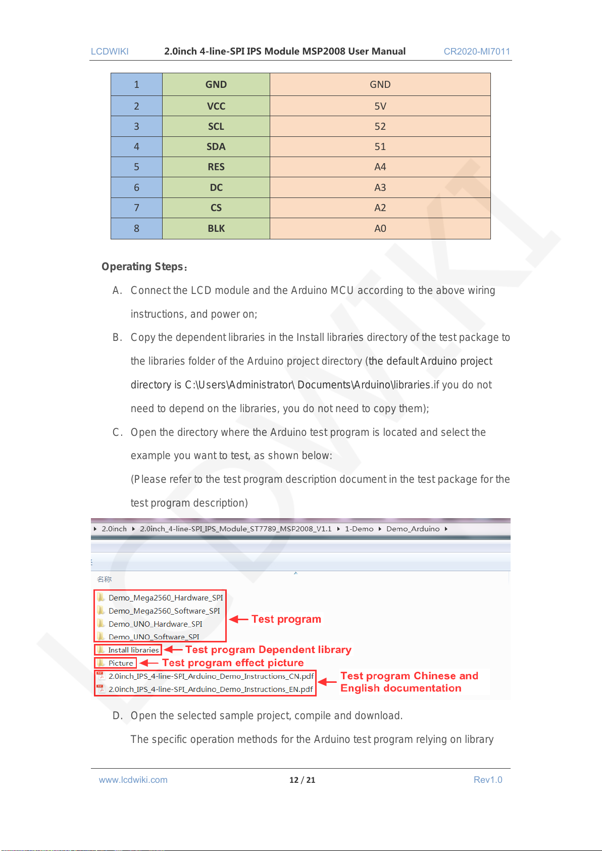
C. Open the directory where the Arduino test program is located and select the
example you want to test, as shown below:
(Please refer to the test program description document in the test package for the
test program description)
D. Open the selected sample project, compile and download.
The specific operation methods for the Arduino test program relying on library
www.lcdwiki.com 12 / 21 Rev1.0
Page 13
LCDWIKI 2.0inch 4-line-SPI IPS Module MSP2008 User Manual CR2020-MI7011
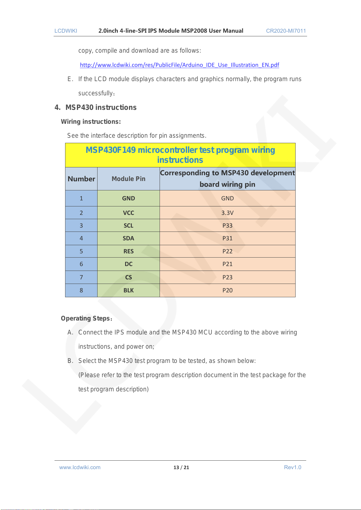
MSP430F149 microcontroller test program wiring
instructions
Number
Module Pin
Corresponding to MSP430 development
board wiring pin
1
GND
GND
2
VCC
3.3V
3
SCL
P33
4
SDA
P31
5
RES
P22
6
DC
P21
7
CS
P23
8
BLK
P20
copy, compile and download are as follows:
http://www.lcdwiki.com/res/PublicFile/Arduino_IDE_Use_Illustration_EN.pdf
E. If the LCD module displays characters and graphics normally, the program runs
successfully;
4. MSP430 instructions
Wiring instructions:
See the interface description for pin assignments.
Operating Steps:
A. Connect the IPS module and the MSP430 MCU according to the above wiring
instructions, and power on;
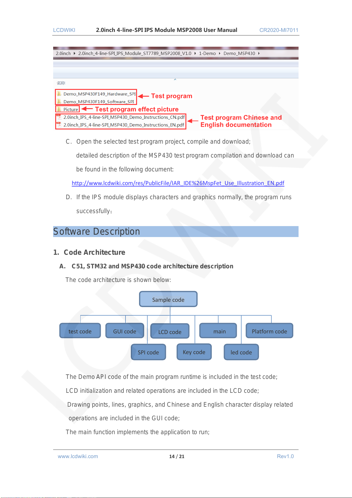
B. Select the MSP430 test program to be tested, as shown below:
(Please refer to the test program description document in the test package for the
test program description)
www.lcdwiki.com 13 / 21 Rev1.0
Page 14
LCDWIKI 2.0inch 4-line-SPI IPS Module MSP2008 User Manual CR2020-MI7011
Sample code
test code
GUI code
LCD code
main
Platform code
SPI code
led code
Key code
C. Open the selected test program project, compile and download;
detailed description of the MSP430 test program compilation and download can
be found in the following document:
http://www.lcdwiki.com/res/PublicFile/IAR_IDE%26MspFet_Use_Illustration_EN.pdf
D. If the IPS module displays characters and graphics normally, the program runs
successfully;
Software Description
1. Code Architecture
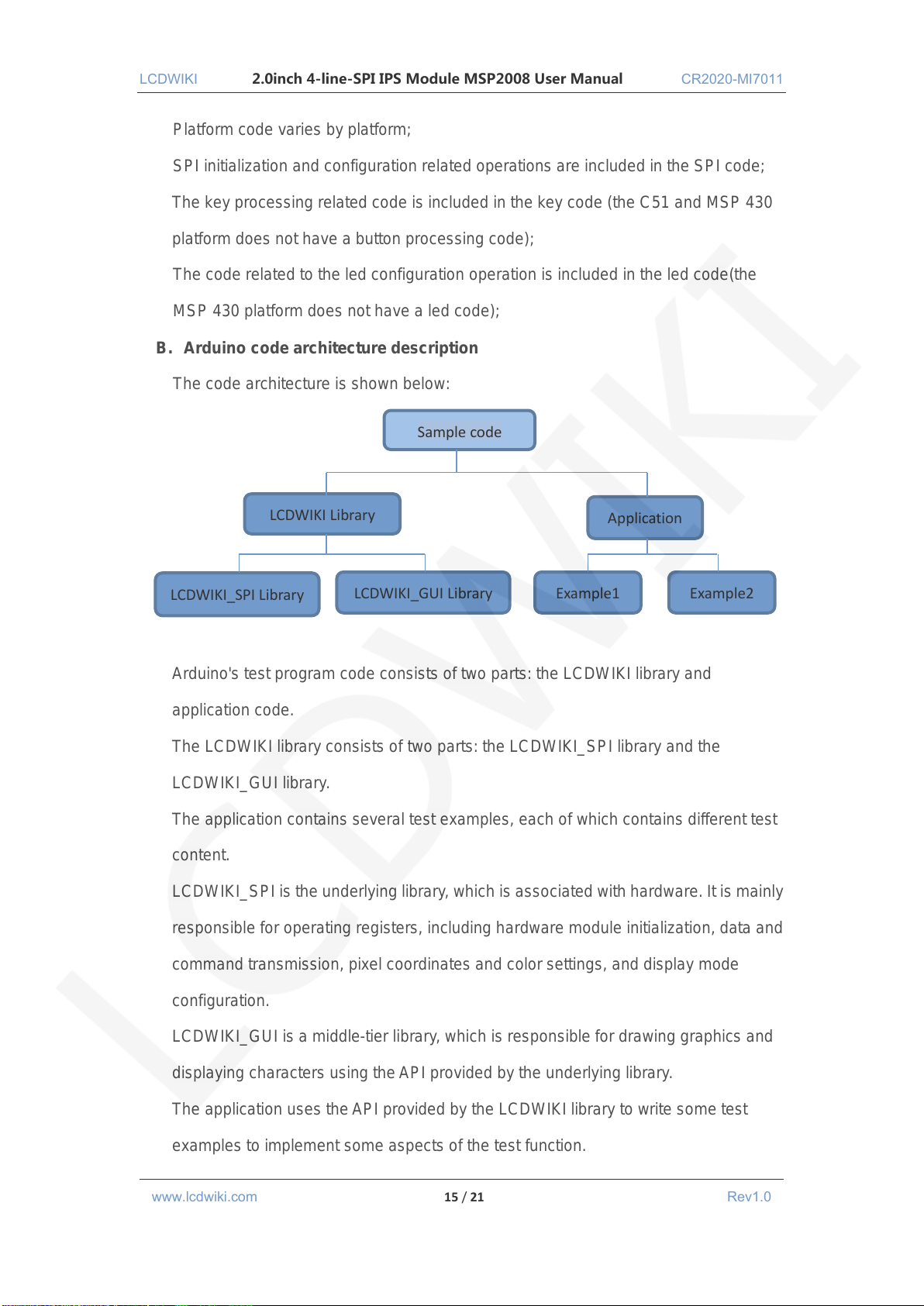
A. C51, STM32 and MSP430 code architecture description
The code architecture is shown below:
The Demo API code of the main program runtime is included in the test code;
LCD initialization and related operations are included in the LCD code;
Drawing points, lines, graphics, and Chinese and English character display related
operations are included in the GUI code;
The main function implements the application to run;
www.lcdwiki.com 14 / 21 Rev1.0
Page 15
LCDWIKI 2.0inch 4-line-SPI IPS Module MSP2008 User Manual CR2020-MI7011
Sample code
LCDWIKI Library
Application
LCDWIKI_SPI Library
LCDWIKI_GUI Library
Example1
Example2
Platform code varies by platform;
SPI initialization and configuration related operations are included in the SPI code;
The key processing related code is included in the key code (the C51 and MSP 430
platform does not have a button processing code);
The code related to the led configuration operation is included in the led code(the
MSP 430 platform does not have a led code);
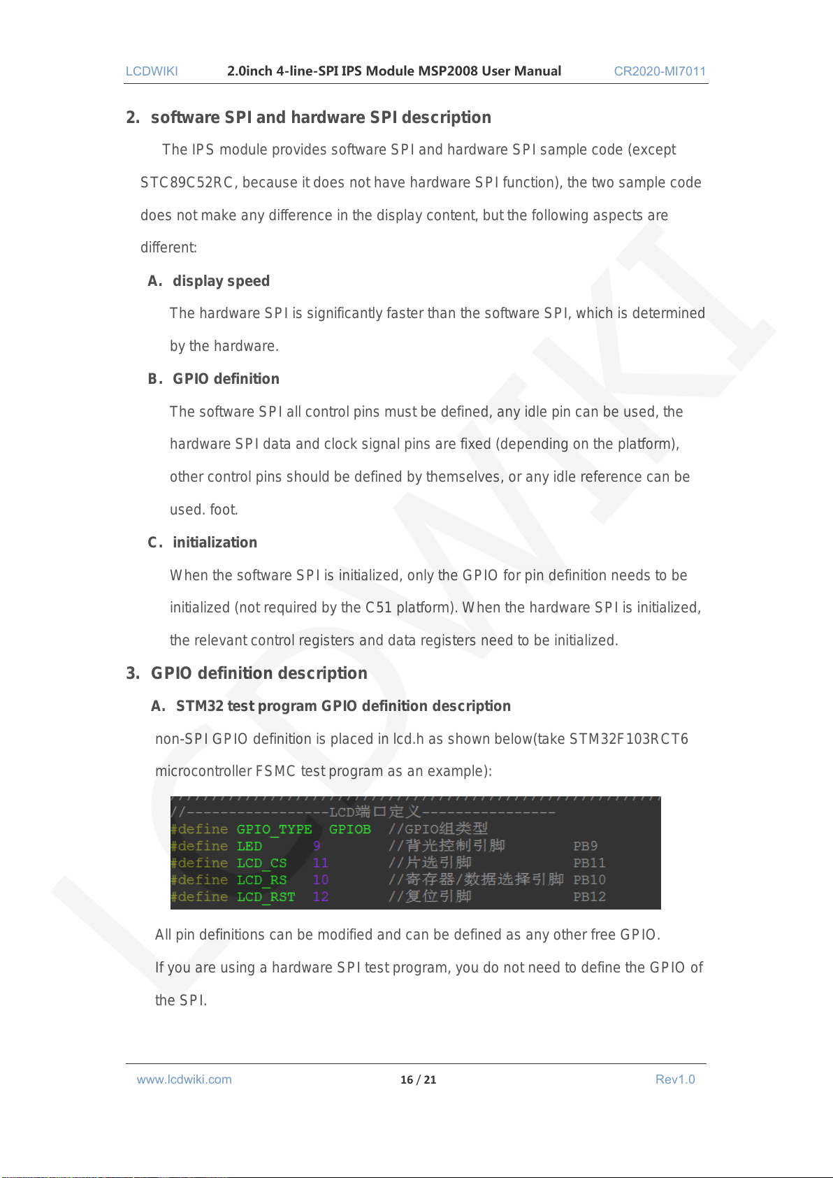
B. Arduino code architecture description
The code architecture is shown below:
Arduino's test program code consists of two parts: the LCDWIKI library and
application code.
The LCDWIKI library consists of two parts: the LCDWIKI_SPI library and the
LCDWIKI_GUI library.
The application contains several test examples, each of which contains different test
content.
LCDWIKI_SPI is the underlying library, which is associated with hardware. It is mainly
responsible for operating registers, including hardware module initialization, data and
command transmission, pixel coordinates and color settings, and display mode
configuration.
LCDWIKI_GUI is a middle-tier library, which is responsible for drawing graphics and
displaying characters using the API provided by the underlying library.
The application uses the API provided by the LCDWIKI library to write some test
examples to implement some aspects of the test function.
www.lcdwiki.com 15 / 21 Rev1.0
Page 16
LCDWIKI 2.0inch 4-line-SPI IPS Module MSP2008 User Manual CR2020-MI7011
2. software SPI and hardware SPI description
The IPS module provides software SPI and hardware SPI sample code (except
STC89C52RC, because it does not have hardware SPI function), the two sample code
does not make any difference in the display content, but the following aspects are
different:
A. display speed
The hardware SPI is significantly faster than the software SPI, which is determined
by the hardware.
B. GPIO definition
The software SPI all control pins must be defined, any idle pin can be used, the
hardware SPI data and clock signal pins are fixed (depending on the platform),
other control pins should be defined by themselves, or any idle reference can be
used. foot.
C. initialization
When the software SPI is initialized, only the GPIO for pin definition needs to be
initialized (not required by the C51 platform). When the hardware SPI is initialized,
the relevant control registers and data registers need to be initialized.
3. GPIO definition description
A. STM32 test program GPIO definition description
non-SPI GPIO definition is placed in lcd.h as shown below(take STM32F103RCT6
microcontroller FSMC test program as an example):
All pin definitions can be modified and can be defined as any other free GPIO.
If you are using a hardware SPI test program, you do not need to define the GPIO of
the SPI.
www.lcdwiki.com 16 / 21 Rev1.0
Page 17
LCDWIKI 2.0inch 4-line-SPI IPS Module MSP2008 User Manual CR2020-MI7011
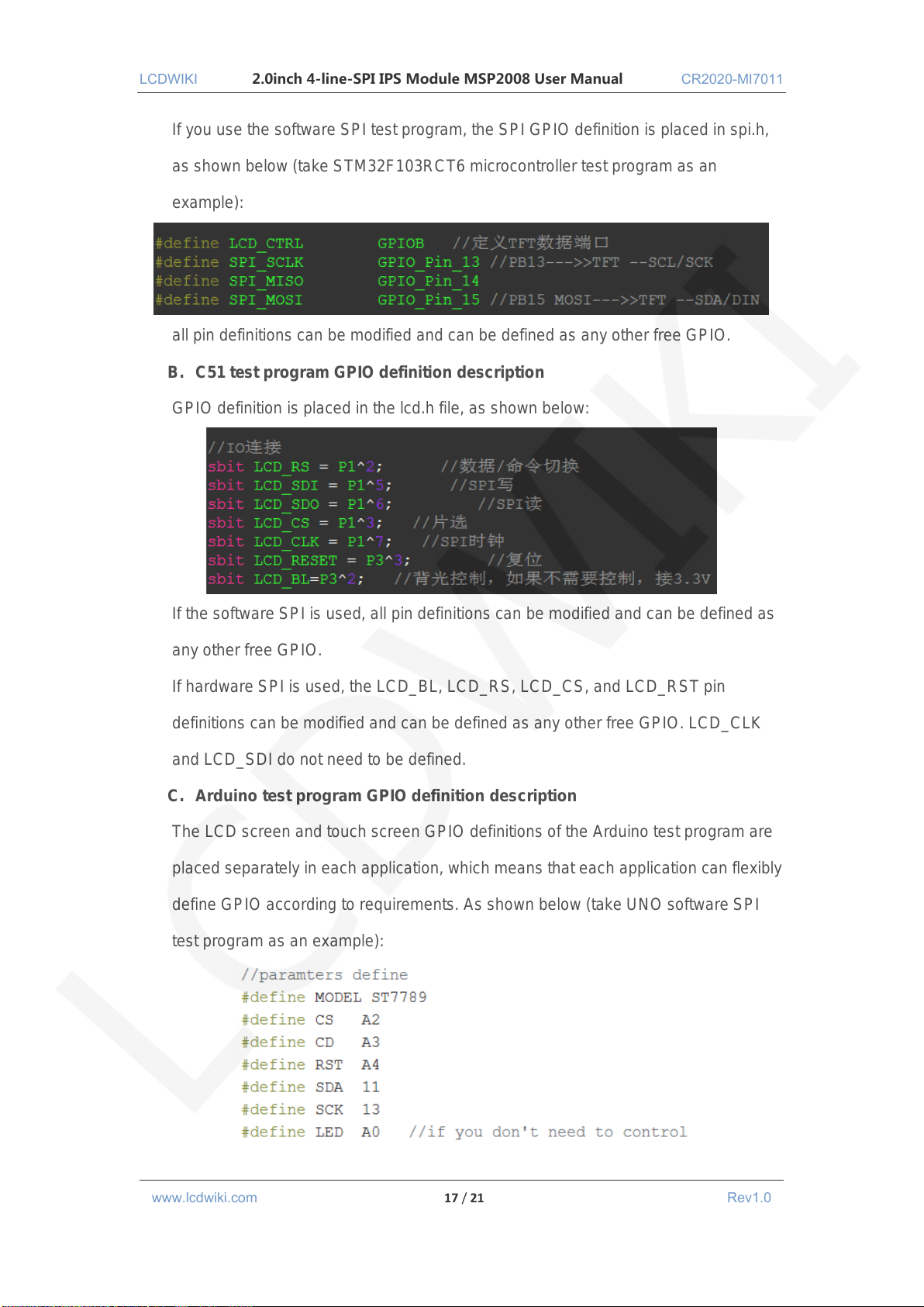
If you use the software SPI test program, the SPI GPIO definition is placed in spi.h,
as shown below (take STM32F103RCT6 microcontroller test program as an
example):
all pin definitions can be modified and can be defined as any other free GPIO.
B. C51 test program GPIO definition description
GPIO definition is placed in the lcd.h file, as shown below:
If the software SPI is used, all pin definitions can be modified and can be defined as
any other free GPIO.
If hardware SPI is used, the LCD_BL, LCD_RS, LCD_CS, and LCD_RST pin
definitions can be modified and can be defined as any other free GPIO. LCD_CLK
and LCD_SDI do not need to be defined.
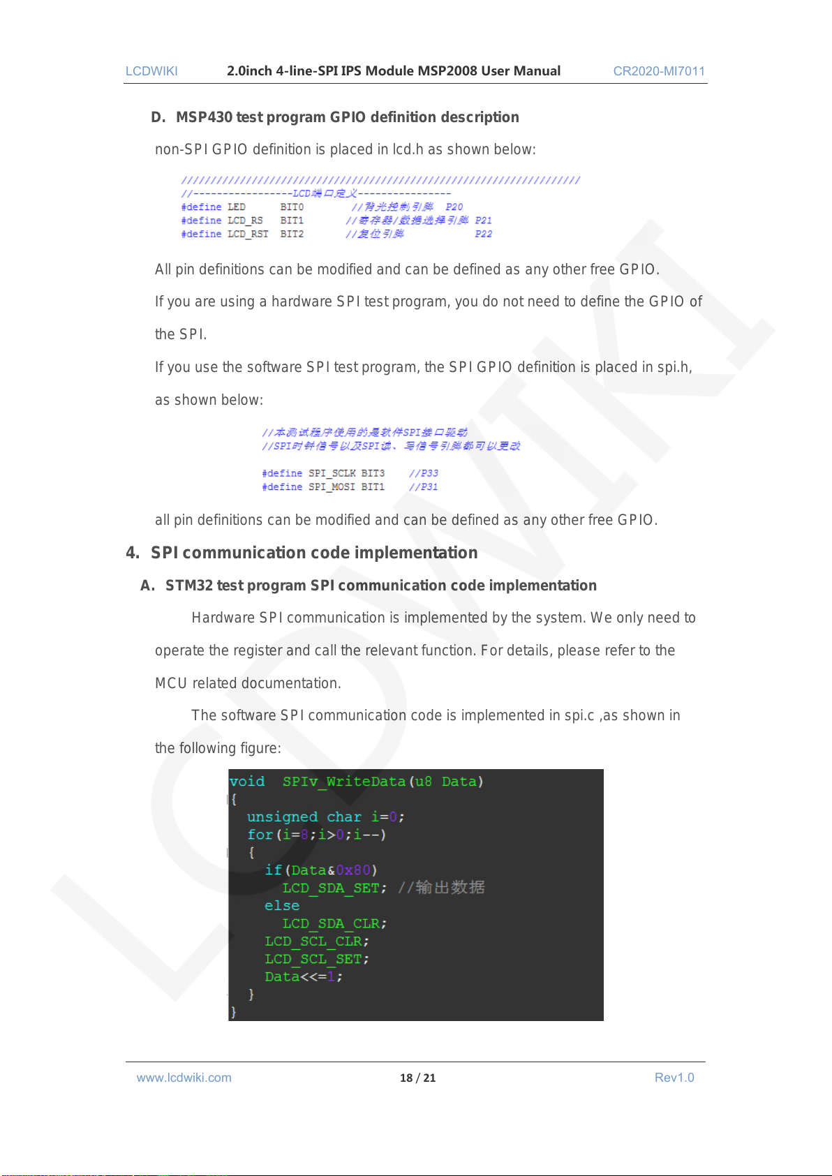
C. Arduino test program GPIO definition description
The LCD screen and touch screen GPIO definitions of the Arduino test program are
placed separately in each application, which means that each application can flexibly
define GPIO according to requirements. As shown below (take UNO software SPI
test program as an example):
www.lcdwiki.com 17 / 21 Rev1.0
Page 18
LCDWIKI 2.0inch 4-line-SPI IPS Module MSP2008 User Manual CR2020-MI7011
D. MSP430 test program GPIO definition description
non-SPI GPIO definition is placed in lcd.h as shown below:
All pin definitions can be modified and can be defined as any other free GPIO.
If you are using a hardware SPI test program, you do not need to define the GPIO of
the SPI.
If you use the software SPI test program, the SPI GPIO definition is placed in spi.h,
as shown below:
all pin definitions can be modified and can be defined as any other free GPIO.
4. SPI communication code implementation
A. STM32 test program SPI communication code implementation
Hardware SPI communication is implemented by the system. We only need to
operate the register and call the relevant function. For details, please refer to the
MCU related documentation.
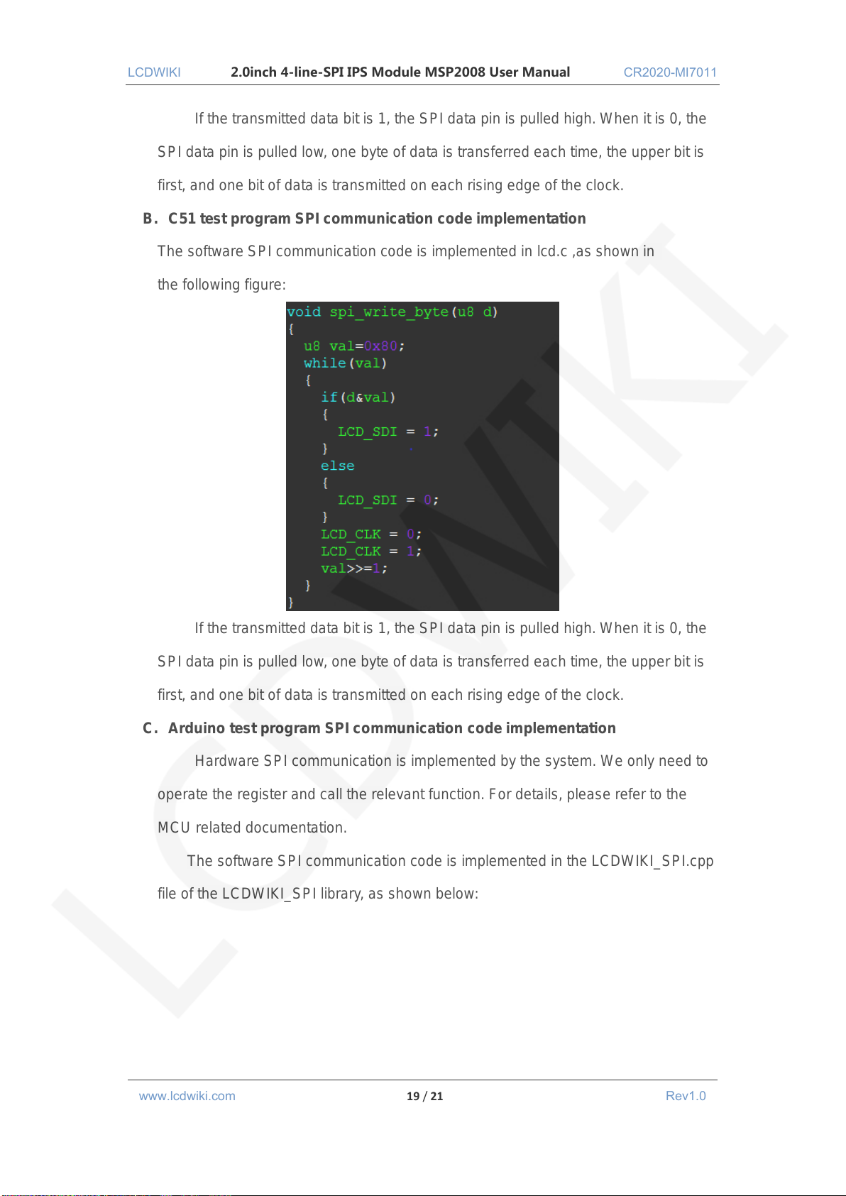
The software SPI communication code is implemented in spi.c ,as shown in
the following figure:
www.lcdwiki.com 18 / 21 Rev1.0
Page 19
LCDWIKI 2.0inch 4-line-SPI IPS Module MSP2008 User Manual CR2020-MI7011
If the transmitted data bit is 1, the SPI data pin is pulled high. When it is 0, the
SPI data pin is pulled low, one byte of data is transferred each time, the upper bit is
first, and one bit of data is transmitted on each rising edge of the clock.
B. C51 test program SPI communication code implementation
The software SPI communication code is implemented in lcd.c ,as shown in
the following figure:
If the transmitted data bit is 1, the SPI data pin is pulled high. When it is 0, the
SPI data pin is pulled low, one byte of data is transferred each time, the upper bit is
first, and one bit of data is transmitted on each rising edge of the clock.
C. Arduino test program SPI communication code implementation
Hardware SPI communication is implemented by the system. We only need to
operate the register and call the relevant function. For details, please refer to the
MCU related documentation.
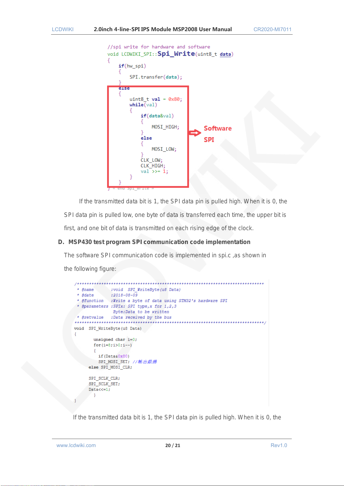
The software SPI communication code is implemented in the LCDWIKI_SPI.cpp
file of the LCDWIKI_SPI library, as shown below:
www.lcdwiki.com 19 / 21 Rev1.0
Page 20
LCDWIKI 2.0inch 4-line-SPI IPS Module MSP2008 User Manual CR2020-MI7011
If the transmitted data bit is 1, the SPI data pin is pulled high. When it is 0, the
SPI data pin is pulled low, one byte of data is transferred each time, the upper bit is
first, and one bit of data is transmitted on each rising edge of the clock.
D. MSP430 test program SPI communication code implementation
The software SPI communication code is implemented in spi.c ,as shown in
the following figure:
If the transmitted data bit is 1, the SPI data pin is pulled high. When it is 0, the
www.lcdwiki.com 20 / 21 Rev1.0
Page 21
LCDWIKI 2.0inch 4-line-SPI IPS Module MSP2008 User Manual CR2020-MI7011
SPI data pin is pulled low, one byte of data is transferred each time, the upper bit is
first, and one bit of data is transmitted on each rising edge of the clock.
Common software
This set of test examples requires the display of Chinese and English, symbols and
pictures, so the modulo software is used. There are two types of modulo software:
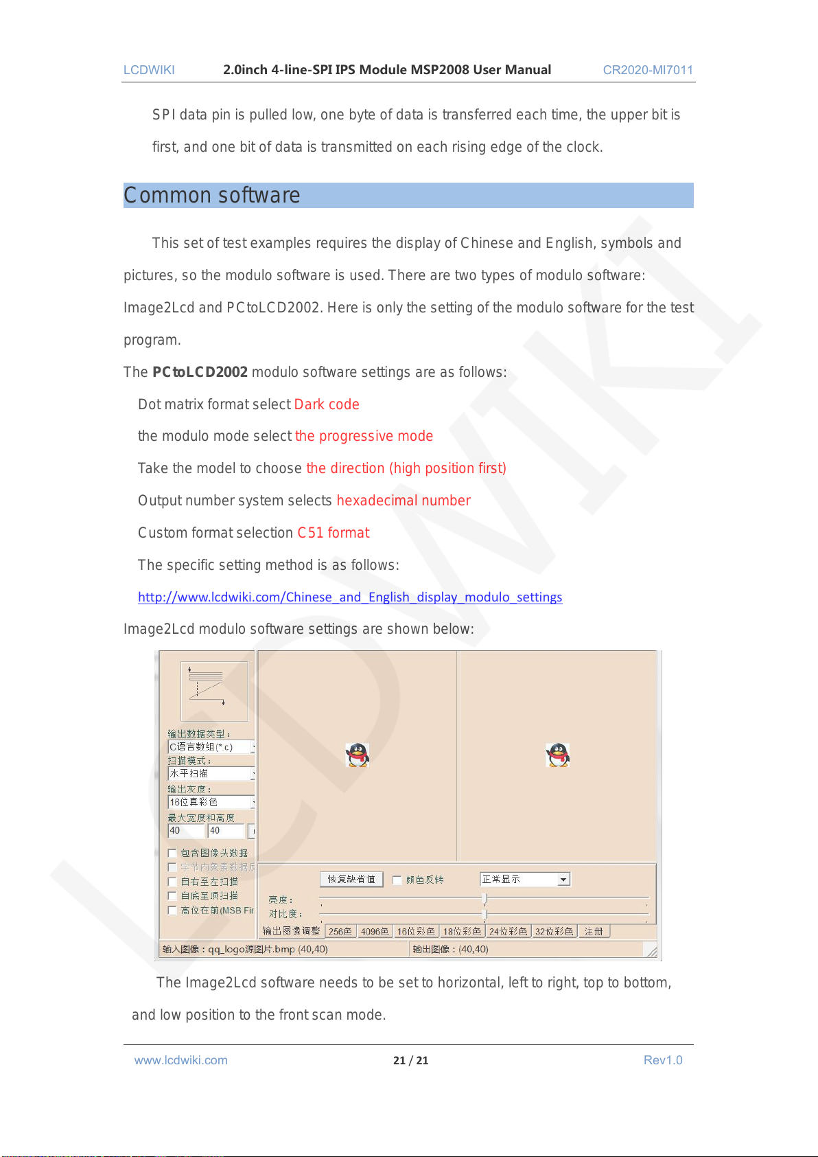
Image2Lcd and PCtoLCD2002. Here is only the setting of the modulo software for the test
program.
The PCtoLCD2002 modulo software settings are as follows:
Dot matrix format select Dark code
the modulo mode select the progressive mode
Take the model to choose the direction (high position first)
Output number system selects hexadecimal number
Custom format selection C51 format
The specific setting method is as follows:
http://www.lcdwiki.com/Chinese_and_English_display_modulo_settings
Image2Lcd modulo software settings are shown below:
The Image2Lcd software needs to be set to horizontal, left to right, top to bottom,
and low position to the front scan mode.
www.lcdwiki.com 21 / 21 Rev1.0
 Loading...