

Page 1
DDU4F
5-TAP, TTL-INTERFACED
data
3
1
14
IN
VDD
FIXED DELAY LINE
(SERIES DDU4F)
delay
devices,
inc.
FEATURES PACKAGES
IN
• Five equally spaced outputs
1
• Fits standard 14-pin DIP socket
T2
GND
4
T4
6
7
• Low profile
• Auto-insertable
• Input & outputs fully TTL interfaced & buffered
• 10 T2L fan-out capability
DDU4F-xx DIP
DDU4F-xxA2 Gull-Wing
DDU4F-xxB2 J-Lead
DDU4F-xxM Military DIP
FUNCTIONAL DESCRIPTION
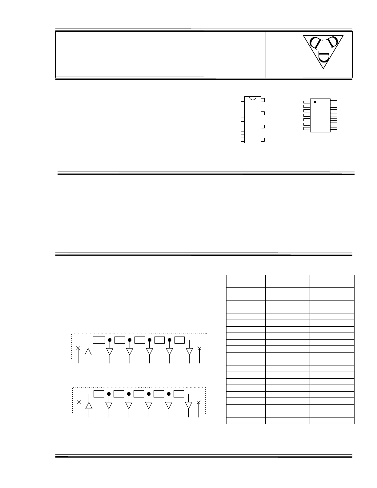
The DDU4F-series device is a 5-tap digitally buffered delay line. The
signal input (IN) is reproduced at the outputs (T1-T5), shifted in time by an
amount determined by the device dash number (See Table). For dash
numbers less than 5025, the total delay of the line is measured from T1 to
T5. The nominal tap-to-tap delay increment is given by one-fourth of the
total delay, and the inherent delay from IN to T1 is nominally 3.5ns. For
dash numbers greater than or equal to 5025, the total delay of the line is measured from IN to T5. The
nominal tap-to-tap delay increment is given by one-fifth of this number.
VCC
14
T1
12
T3
10
T5
8
GND
N/C
N/C
T2
N/C
T4
2
13
3
12
4
11
5
10
6
9
7
8
Military SMD
DDU4F-xxMC2
PIN DESCRIPTIONS
IN Signal Input
T1-T5 Tap Outputs
VCC +5 Volts
GND Ground
N/C
T1
N/C
T3
N/C
T5
SERIES SPECIFICATIONS
• Minimum input pulse width: 20% of total delay
• Output rise time: 2ns typical
• Supply voltage: 5VDC ± 5%
• Supply current: I
I
• Operating temperature: 0° to 70° C
• Temp. coefficient of total delay: 100 PPM/°C
3.5ns
VCC GNDIN T1 T2 T3 T4 T5
Functional diagram for dash numbers < 5025
20% 20% 20% 20% 20%
VCC GNDIN T1 T2 T3 T4 T5
Functional diagram for dash numbers >= 5025
1997 Data Delay Devices
= 32ma typical
CCL
= 7ma typical
CCH
25% 25% 25% 25%
DASH NUMBER SPECIFICATIONS
Part
Number
DDU4F-5004
DDU4F-5006
DDU4F-5008
DDU4F-5010
DDU4F-5012
DDU4F-5016
DDU4F-5020
DDU4F-5025
DDU4F-5030
DDU4F-5040
DDU4F-5050
DDU4F-5060
DDU4F-5075
DDU4F-5100
DDU4F-5125
DDU4F-5150
DDU4F-5200
DDU4F-5250
DDU4F-5300
DDU4F-5400
DDU4F-5500
* Total delay is referenced to first tap output
Input to first tap = 3.5ns ±± 1ns
NOTE: Any dash number between 5004 and 5500
Total
Delay (ns)
4 ± 1.0 * 1.0 ± 0.5
6 ± 1.0 * 1.5 ± 0.5
8 ± 2.0 * 2.0 ± 1.0
10 ± 2.0 * 2.5 ± 1.0
12 ± 2.0 * 3.0 ± 1.0
16 ± 2.0 * 4.0 ± 1.5
20 ± 3.0 * 5.0 ± 2.0
25 ± 3.0 5.0 ± 2.0
30 ± 3.0 6.0 ± 2.0
40 ± 3.0 8.0 ± 2.0
50 ± 3.0 10.0 ± 3.0
60 ± 3.0 12.0 ± 3.0
75 ± 4.0 15.0 ± 3.0
100 ± 5.0 20.0 ± 3.0
125 ± 6.5 25.0 ± 3.0
150 ± 7.5 30.0 ± 3.0
200 ± 10.0 40.0 ± 4.0
250 ± 12.5 50.0 ± 5.0
300 ± 15.0 60.0 ± 6.0
400 ± 20.0 80.0 ± 8.0
500 ± 25.0 100.0 ± 10.0
Delay Per
Tap (ns)
Doc #97033 DATA DELAY DEVICES, INC. 1
12/10/97 3 Mt. Prospect Ave. Clifton, NJ 07013
Page 2
DDU4F
APPLICATION NOTES
HIGH FREQUENCY RESPONSE
The DDU4F tolerances are guaranteed for input
pulse widths and periods greater than those
specified in the test conditions. Although the
device will function properly for pulse widths as
small as 20% of the total delay and periods as
small as 40% of the total delay (for a symmetric
input), the delays may deviate from their values at
low frequency. However, for a given input
condition, the deviation will be repeatable from
pulse to pulse. Contact technical support at Data
DEVICE SPECIFICATIONS
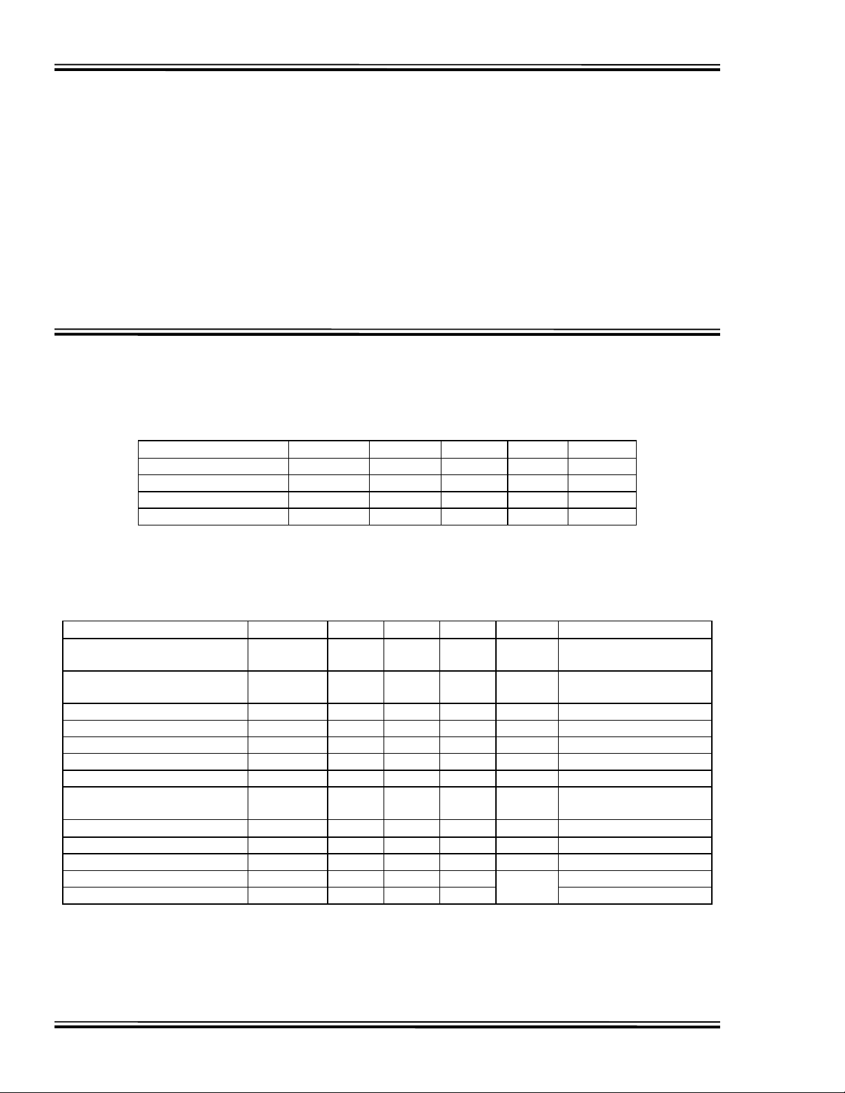
TABLE 1: ABSOLUTE MAXIMUM RATINGS
PARAMETER SYMBOL MIN MAX UNITS NOTES
DC Supply Voltage V
Input Pin Voltage V
Storage Temperature T
Lead Temperature T
CC
IN
STRG
LEAD
Delay Devices if your application requires device
testing at a specific input condition.
POWER SUPPLY BYPASSING
The DDU4F relies on a stable power supply to
produce repeatable delays within the stated
tolerances. A 0.1uf capacitor from VCC to GND,
located as close as possible to the VCC pin, is
recommended. A wide VCC trace and a clean
ground plane should be used.
-0.3 7.0 V
-0.3 VDD+0.3 V
-55 150 C
300 C 10 sec
TABLE 2: DC ELECTRICAL CHARACTERISTICS
(0C to 70C, 4.75V to 5.25V)
PARAMETER SYMBOL MIN TYP MAX UNITS NOTES
High Level Output Voltage V
Low Level Output Voltage V
High Level Output Current I
Low Level Output Current I
High Level Input Voltage V
Low Level Input Voltage V
Input Clamp Voltage V
Input Current at Maximum
I
OH
OL
OH
OL
IH
IL
IK
IHH
Input Voltage
High Level Input Current I
Low Level Input Current I
Short-circuit Output Current I
IH
IL
OS
Output High Fan-out 25 Unit
Output Low Fan-out 12.5 Load
2.5 3.4 V VCC = MIN, IOH = MAX
0.35 0.5 V VCC = MIN, IOL = MAX
-1.0 mA
20.0 mA
2.0 V
0.8 V
-1.2 V VCC = MIN, II = I
0.1 mA VCC = MAX, VI = 7.0V
20
µA
-0.6 mA VCC = MAX, VI = 0.5V
-60 -150 mA VCC = MAX
VIH = MIN, VIL = MAX
VIH = MIN, VIL = MAX
IK
VCC = MAX, VI = 2.7V
Doc #97033 DATA DELAY DEVICES, INC. 2
12/10/97 Tel: 973-773-2299 Fax: 973-773-9672 http://www.datadelay.com
Page 3
DDU4F
DDU4F-xx (Commercial DIP)
1 4 6 7
DDU4F-xxM (Military DIP)
DDU4F-xxMC2 (Military SMD)
.780±.020
.010±.002
.780 MAX.
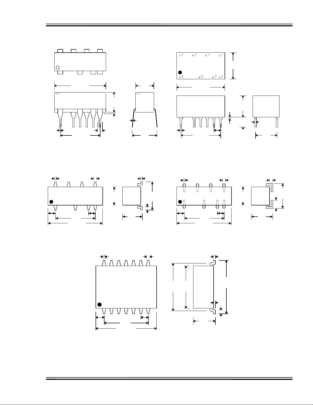
PACKAGE DIMENSIONS
814 12 10
Lead Material:
Nickel-Iron alloy 42
TIN PLATE
.280
MAX.
1 4 6 7
.820 MAX.
814 12 10
.410
TYP.
.290
MAX.
.018
TYP.
.020 TYP.
1 4 6 7
.600±.010
.600
.790 MAX.
.015 TYP.
.070 MAX.
.040
TYP.
8101214
.270
TYP.
.100.090
.010±.002
.010 TYP.
.300
MAX.
DDU4F-xxA2 (Commercial Gull-Wing)
.350
MAX.
.430
TYP.
.050
TYP.
.320
.020
MAX.
TYP.
.130
.030
.018 TYP.
.600 TYP.
.020 TYP.
1 4 6 7
.600
.790 MAX.
.100
TYP.
101214
.100.110
±
.040
TYP.
8
.270
TYP.
.020 TYP.
.300
TYP.
.050 TYP.
.350
MAX.
DDU4F-xxB2 (Commercial J-Lead)
.320
TYP.
.110
TYP.
Doc #97033 DATA DELAY DEVICES, INC. 3
12/10/97 3 Mt. Prospect Ave. Clifton, NJ 07013
.020 TYP. .040
91011121314
1 2 3 4 5 6 7
.100.090
.600
TYP.
8
.007
.005
±
±
.050
.010
±
.882
.005
.710
.005
±
.590
MAX.
.280
MAX.
Page 4
DDU4F
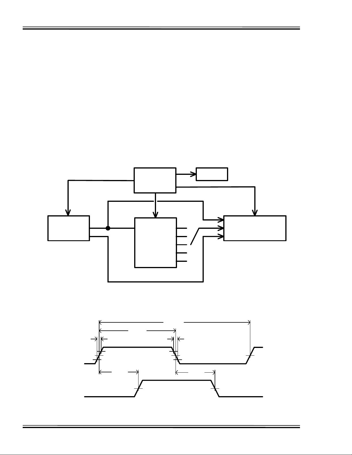
DELAY LINE AUTOMATED TESTING
TEST CONDITIONS
INPUT: OUTPUT:
Ambient Temperature: 25oC ± 3oC Load: 1 FAST-TTL Gate
Supply Voltage (Vcc): 5.0V ± 0.1V C
Input Pulse: High = 3.0V ± 0.1V Threshold: 1.5V (Rising & Falling)
Low = 0.0V ± 0.1V
Source Impedance: 50Ω Max.
Rise/Fall Time: 3.0 ns Max. (measured
between 0.6V and 2.4V )
Pulse Width: PWIN = 1.5 x Total Delay
Period: PERIN = 10 x Total Delay
NOTE: The above conditions are for test only and do not in any way restrict the operation of the device.
: 5pf ± 10%
load
PULSE
GENERATOR
TRIG
T
RISE
IN
DEVICE UNDER
PW
IN
COMPUTER
SYSTEM
TEST (DUT)
Test Setup
PER
PRINTER
REF
T1OUT
T2
T3
T4
T5
IN
T
FALL
IN
TRIG
TIME INTERVAL
COUNTER
INPUT
SIGNAL
OUTPUT
SIGNAL
2.4V 2.4V
T
RISE
V
IH
1.5V1.5V
0.6V0.6V
V
OH
T
FALL
V
IL
1.5V1.5V
V
OL
Timing Diagram For Testing
Doc #97033 DATA DELAY DEVICES, INC. 4
12/10/97 Tel: 973-773-2299 Fax: 973-773-9672 http://www.datadelay.com
 Loading...