

Page 1
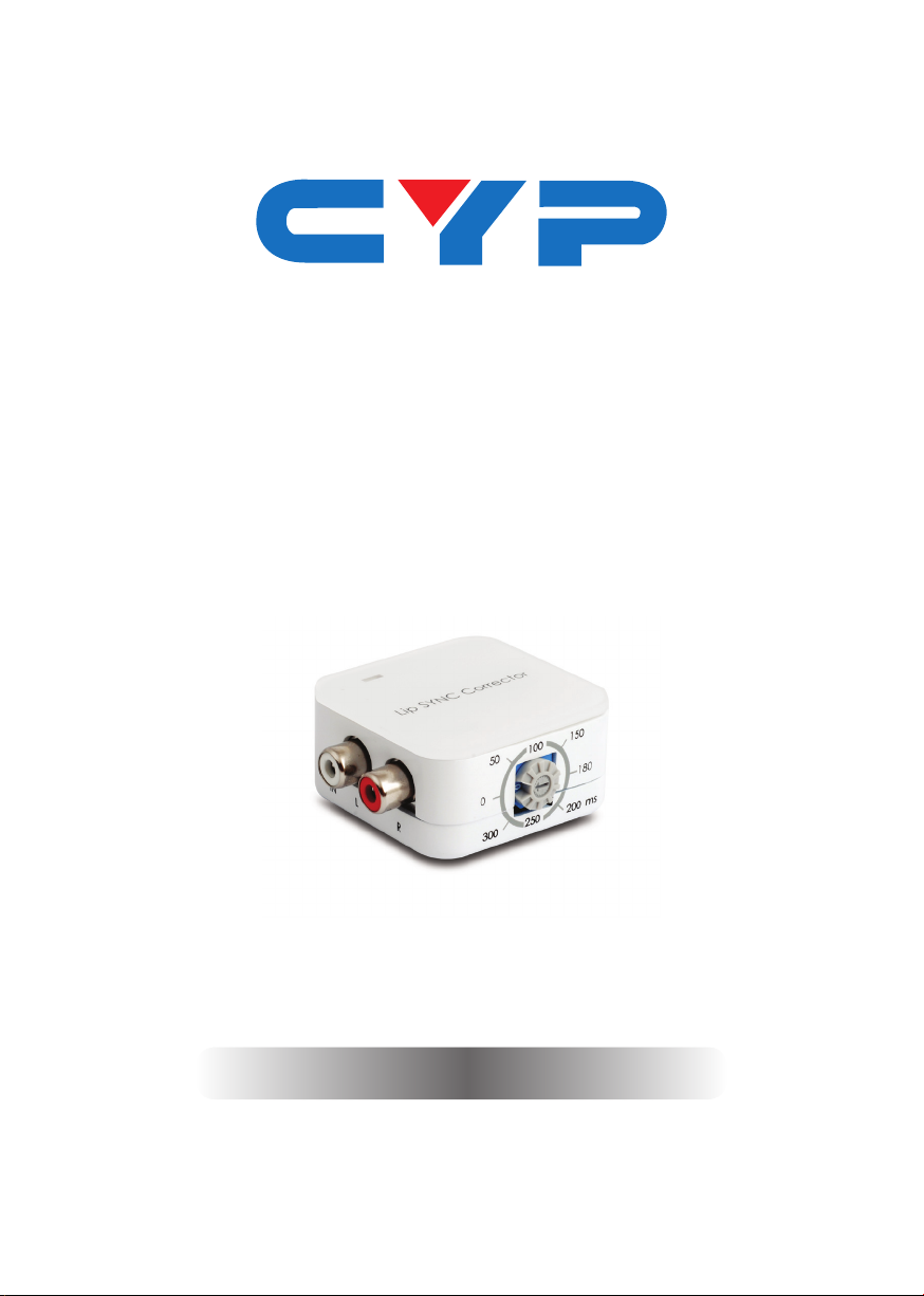
DCT-18
Analog Stereo Lip Sync Corrector
Operation Manual
Operation Manual
Page 2

Page 3

DISCLAIMERS
The information in this manual has been carefully checked and
is believed to be accurate. Cypress Technology assumes no
responsibility for any infringements of patents or other rights of third
parties which may result from its use.
Cypress Technology assumes no responsibility for any inaccuracies
that may be contained in this document. Cypress also makes no
commitment to update or to keep current the information contained
in this document.
Cypress Technology reserves the right to make improvements to this
document and/or product at any time and without notice.
COPYRIGHT NOTICE
No part of this document may be reproduced, transmitted,
transcribed, stored in a retrieval system, or any of its part translated
into any language or computer le, in any form or by any means—
electronic, mechanical, magnetic, optical, chemical, manual, or
otherwise—without express written permission and consent from
Cypress Technology.
© Copyright 2011 by Cypress Technology.
All Rights Reserved.
Version 1.1 August 2011
TRADEMARK ACKNOWLEDGMENTS
All products or service names mentioned in this document may be
trademarks of the companies with which they are associated.
Page 4

SAFETY PRECAUTIONS
Please read all instructions before attempting to unpack, install or
operate this equipment and before connecting the power supply.
Please keep the following in mind as you unpack and install this
equipment:
• Always follow basic safety precautions to reduce the risk of re,
electrical shock and injury to persons.
• To prevent re or shock hazard, do not expose the unit to rain,
moisture or install this product near water.
• Never spill liquid of any kind on or into this product.
• Never push an object of any kind into this product through any
openings or empty slots in the unit, as you may damage parts
inside the unit.
• Do not attach the power supply cabling to building surfaces.
• Use only the supplied power supply unit (PSU). Do not use the PSU
if it is damaged.
• Do not allow anything to rest on the power cabling or allow any
weight to be placed upon it or any person walk on it.
• To protect the unit from overheating, do not block any vents or
openings in the unit housing that provide ventilation and allow for
sufcient space for air to circulate around the unit.
REVISION HISTORY
VERSION NO. DATE DD/MM/YY SUMMARY OF CHANGE
VS1 03/04/13 First Release
Page 5

CONTENTS
1. Introduction ............................................ 1
2. Applications ........................................... 1
3. Package Contents ................................ 1
4. System Requirements ............................ 1
5. Features .................................................. 1
6. Operation Controls and Functions ....... 2
6.1 Top Panel ..........................................2
6.2 Left Panel ..........................................2
6.3 Right Panel ........................................2
6.4 Front Panel ........................................3
6.5 Rear Panel .........................................3
7. Connection Diagram ............................ 4
8. Specications ........................................ 5
9. Acronyms ............................................... 6
Page 6

1. INTRODUCTION
The Analog Stereo Lip Sync Corrector is a compact device that can
correct audio delays between audio and video. When distributing
video over long distances through multiple devices like distribution
ampliers and set-top boxes there can sometimes be a noticeable
delay which results in audio being played before the video. This
device allows you to manually adjust the audio delay from 0 ~300
ms allowing you to perfectly synchronize your audio and video,
eliminating any mismatch.
2. APPLICATIONS
• Home Theater
• Cable TV
• Set-top Box
• Multi-zone AV Receivers
• Audio Matrixing
3. PACKAGE CONTENTS
• 1×Analog Stereo Lip Sync Corrector
• 1×5 V/1 A Power Adaptor
• Operation Manual
4. SYSTEM REQUIREMENTS
• Analog stereo audio source.
5. FEATURES
• Analog to analog signal bypass
• Low power consumption
1
Page 7
6. OPERATION CONTROLS AND FUNCTIONS
1
1
1
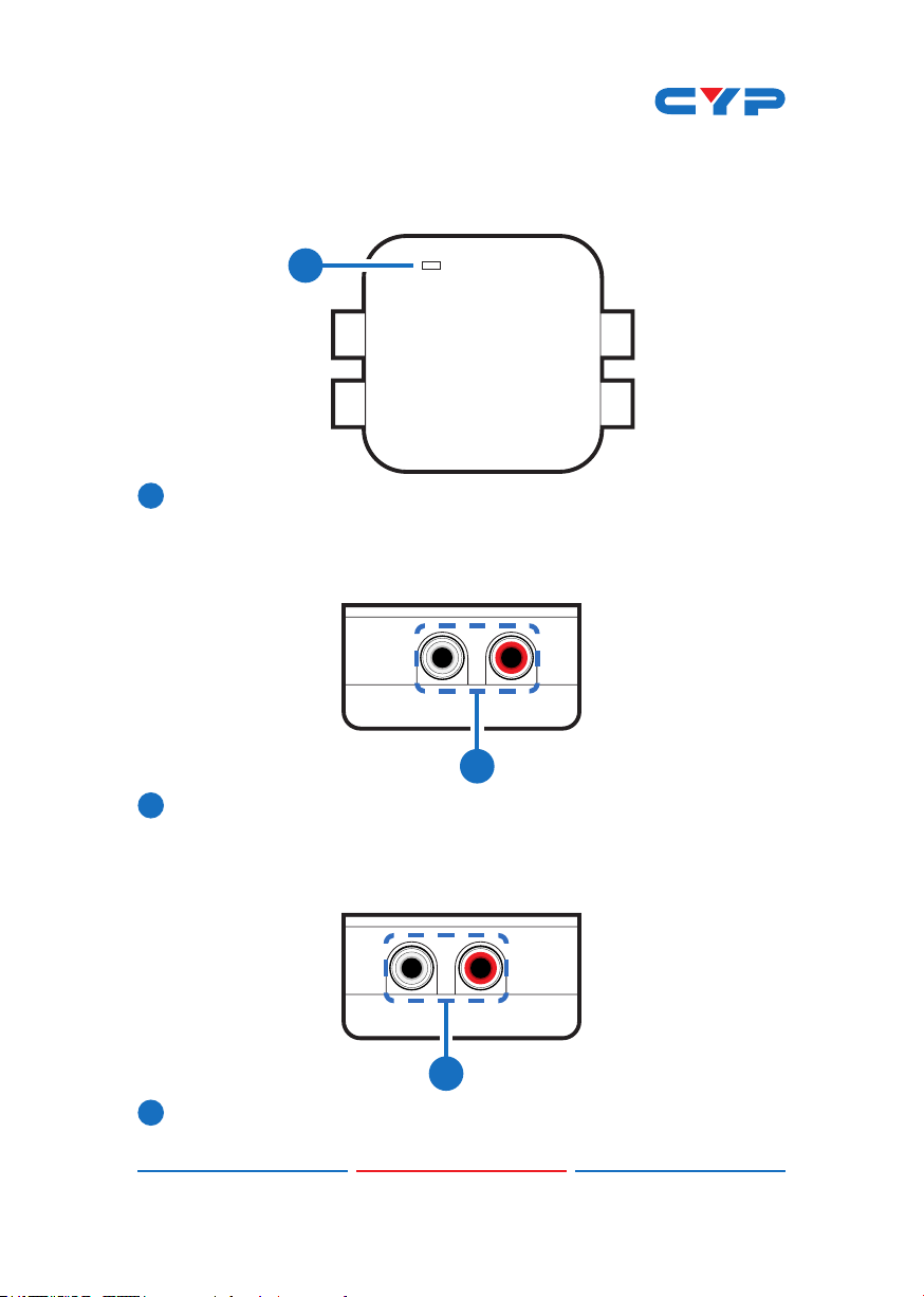
6.1 Top Panel
1
Lip SYNC Corrector
POWER LED: The LED will illuminate in blue when the power is
connected.
6.2 Left Panel
IN RL
1
L/R IN: Connect to the source equipment such as a DVD/Blu-Ray
player with stereo RCA cables to receive the audio signal.
6.3 Right Panel
L
OUTR
1
L/R OUT: Connect to the amplier such as active speakers or TV
with stereo RCA cables to output the received audio signal.
2
Page 8
6.4 Front Panel
1
1
15050
100
0 180
ms
200300
250
1
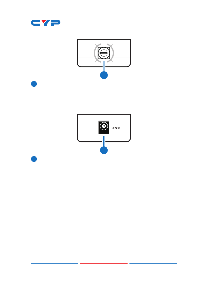
Lip SYNC Switch: This switch has eight settings that allow users to
set the audio output delay from 0~300 milliseconds in order to
perfectly synchronize audio and video signals.
6.5 Rear Panel
DC 5V
1
DC 5V: Connect the 5V DC power supply to the unit and plug the
adaptor to an AC outlet.
3
Page 9
7. CONNECTION DIAGRAM
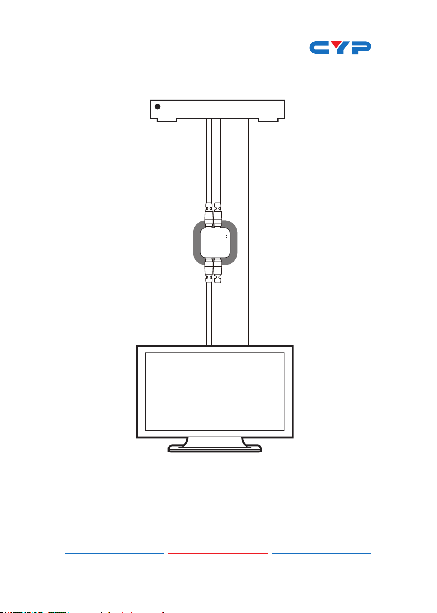
DVD or Blu-ray Player
Analog
Stereo
Input
Analog
Stereo
Output
Lip SYNC Corrector
Video
Input
LCD TV
4
Page 10

8. SPECIFICATIONS
Input Port 1×L/R (with RCA connectors)
Output Port 1×L/R (with RCA connectors)
Input Impedance 44K Ω
Output Impedance 1K Ω
Input Level
Output Level
THD+N
Frequency Response
SNR
Crosstalk
Power Supply 5 V/1 A DC ( US/EU standards, CE/FCC/
ESD Protection Human body model:
Dimensions 55.6 mm (W)×47.5 mm (D)× 23.5 mm (H)
Weight 32 g
Chassis Material Plastic
Silkscreen Color White
Operating Temperature 0 ºC~40 ºC / 32 ºF~104 ºF
Storage Temperature −20 ºC~60 ºC/−4 ºF~140 ºF
Power Consumption 0.5 W
Relative Humidity 20 ~ 90% RH (non-condensing)
2Vrms
2.0Vrms±0.2
<0.01%
±0.5 dB 20Hz~20KHz
>80dB
<-70dB
UL certied)
± 8kV (air-gap discharge)
± 6kV (contact discharge)
5
Page 11

9. ACRONYMS
ACRONYM COMPLETE TERM
Ω Ohm
THD+N
SNR Signal-to-Noise Ratio
RCA
Total Harmonic Distortion plus Noise
Audio Connector (Radio Corporation of America)
6
Page 12

CYPRESS TECHNOLOGY CO., LTD
Home page: http://www.cypress.com.tw
MPM-DCT18
 Loading...