

Page 1
QUICK START GUIDE FOR DEMONSTRATION CIRCUIT 776
DESCRIPTION
36V-72VIN, FORWARD CONVERTER
LTC3705 and LTC3706
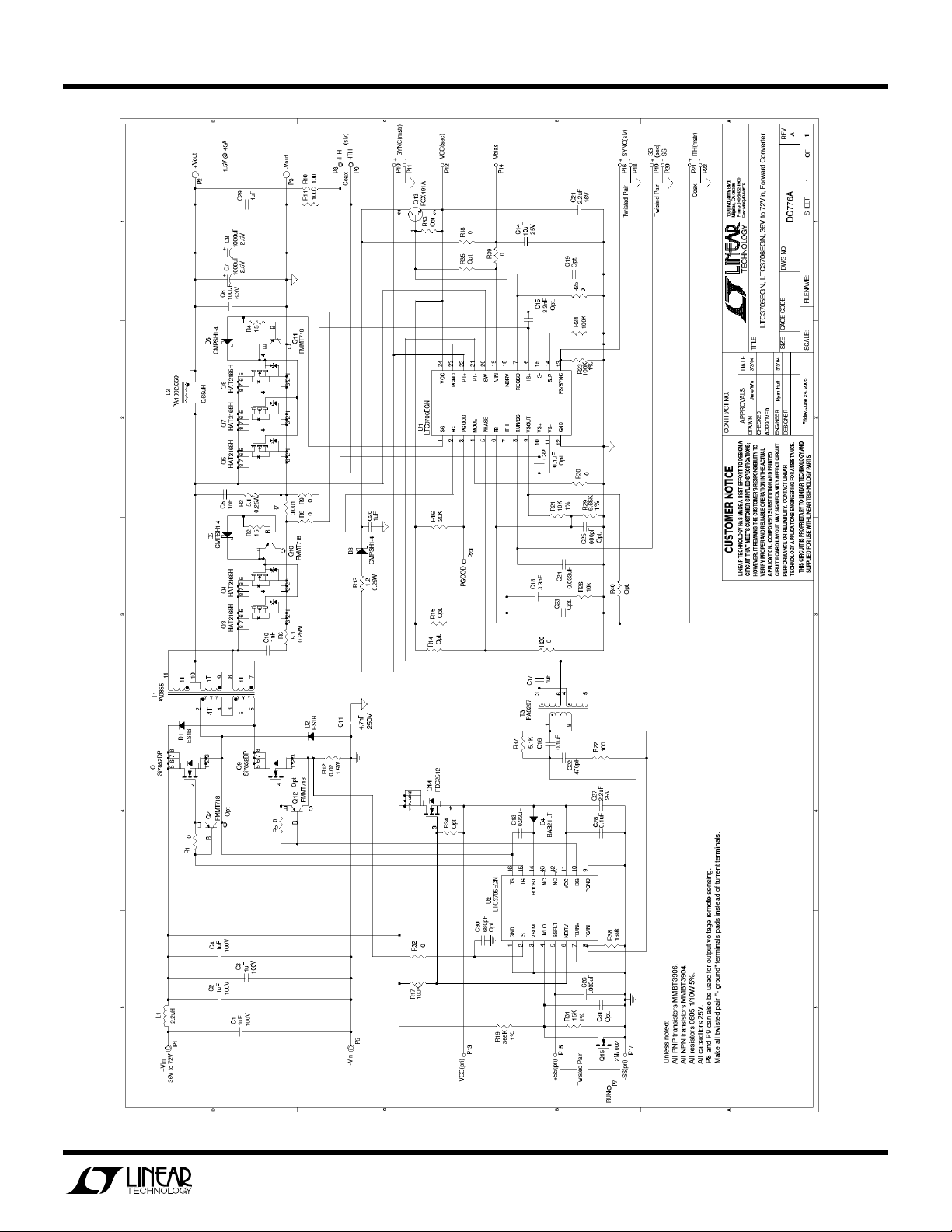
Demonstration circuit 776 is a 36V-72Vin, forward
converter featuring the LTC3705 and LTC3706. This
circuit was designed specifically to attain a high stepdown ratio power supply in one stage in order to efficiently power 1.5V loads from a typical telecom input voltage range. Isolation voltage is 1500VDC.
supply without the need of an optocoupler, selfstarting architecture, input undervoltage lockout, and
output overvoltage protection.
Design files for this circuit board are available.
Call the LTC factory.
, LTC and LT are registered trademarks of Linear Technology Corporation.
This circuit features secondary-side control of the
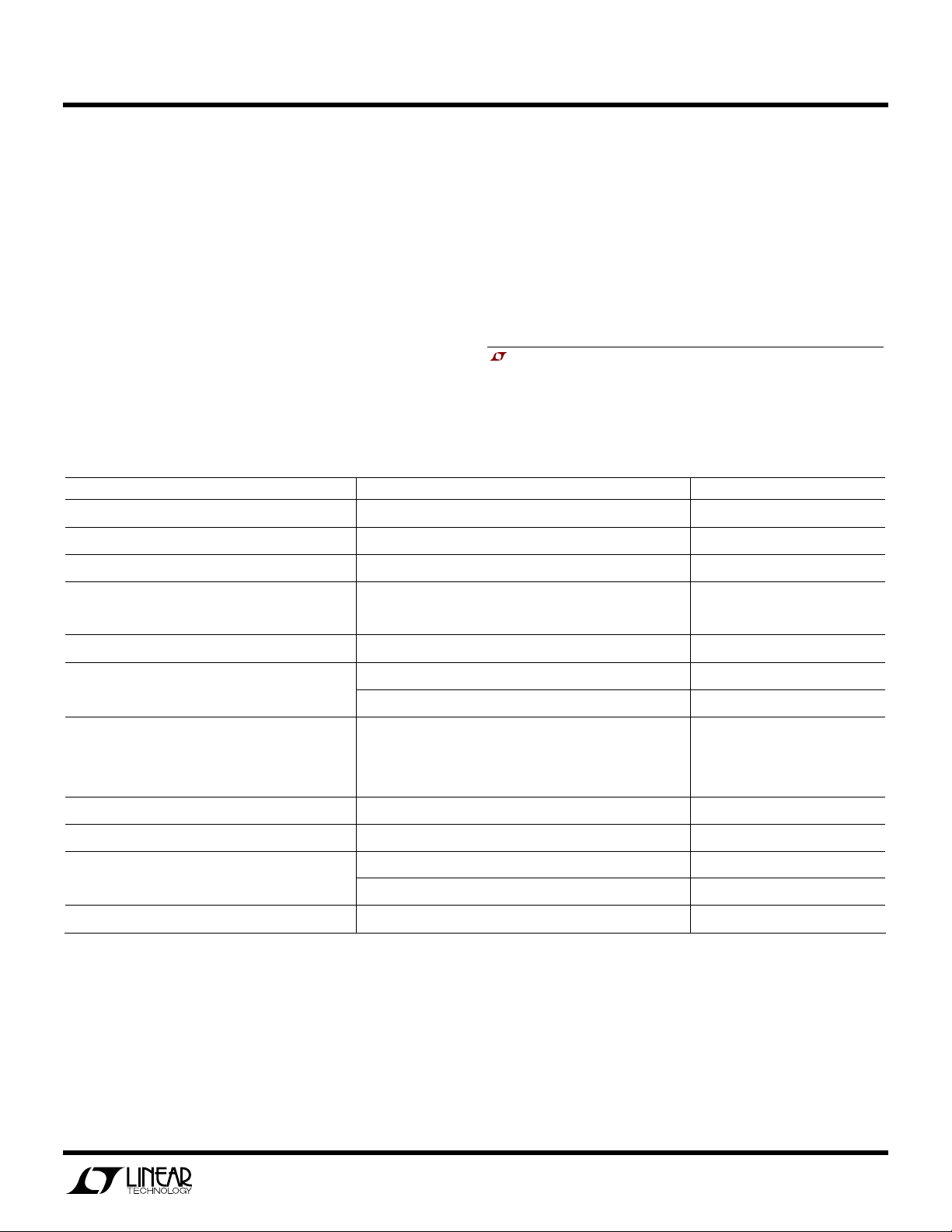
Table 1. Performance Summary (TA = 25°C)
PARAMETER CONDITION VALUE
Minimum Input Voltage 36V
Maximum Input Voltage 72V
Output Voltage V
Maximum Output Current
Typical Output Ripple V
Output Regulation
VIN = 36V to 72V, I
OUT
400LFM
200LFM
VIN = 48V, I
OUT
Line ±0.01%
Load ±0.18%
= 0A to 45A, 400LFM 1.5V ± 1%
OUT
= 30A (20MHz BW) 30mV
OUT
45A
40A
P–P
Peak Deviation
Dynamic Response
Nominal Switching Frequency 215kHz
Efficiency VIN = 48V, I
On/Off Control
Isolation Voltage Basic Insulation 1500VDC
Load Step of 20A to 40A (1A/us min)
Settling Time (to within 15mV of set point)
= 45A, 400LFM 84.75% Typical
OUT
Logic Low Voltage-Off 1V MAX
Logic High Voltage-On 2.5V MIN
65mV
50us
OPERATING PRINCIPLES
The LTC3706 controller is used on the secondary and
the LTC3705 driver with self-starting capability is
used on the primary. When an input voltage is applied, the LTC3705 begins a controlled soft-start of
the output voltage. As this voltage begins to rise, the
LTC3706 secondary controller is quickly powered up
via T1, D3, and Q13. The LTC3706 then assumes
control of the output voltage by sending encoded
1
Page 2

QUICK START GUIDE FOR DEMONSTRATION CIRCUIT 776
36V-72VIN, FORWARD CONVERTER
PWM gate pulses to the LTC3705 primary driver via
the small signal transformer, T3. The LTC3705 then
operates as a simple driver receiving both input signals and bias power through T3.
The transition from primary to secondary control occurs seamlessly at a fraction of the output voltage.
From that point on, operation and design simplifies to
that of a simple buck converter. Secondary sensing
eliminates delays, tames large-signal overshoot and
QUICK START PROCEDURE
Demonstration circuit 776 is easy to set up to evaluate the performance of the LTC3705 and LTC3706.
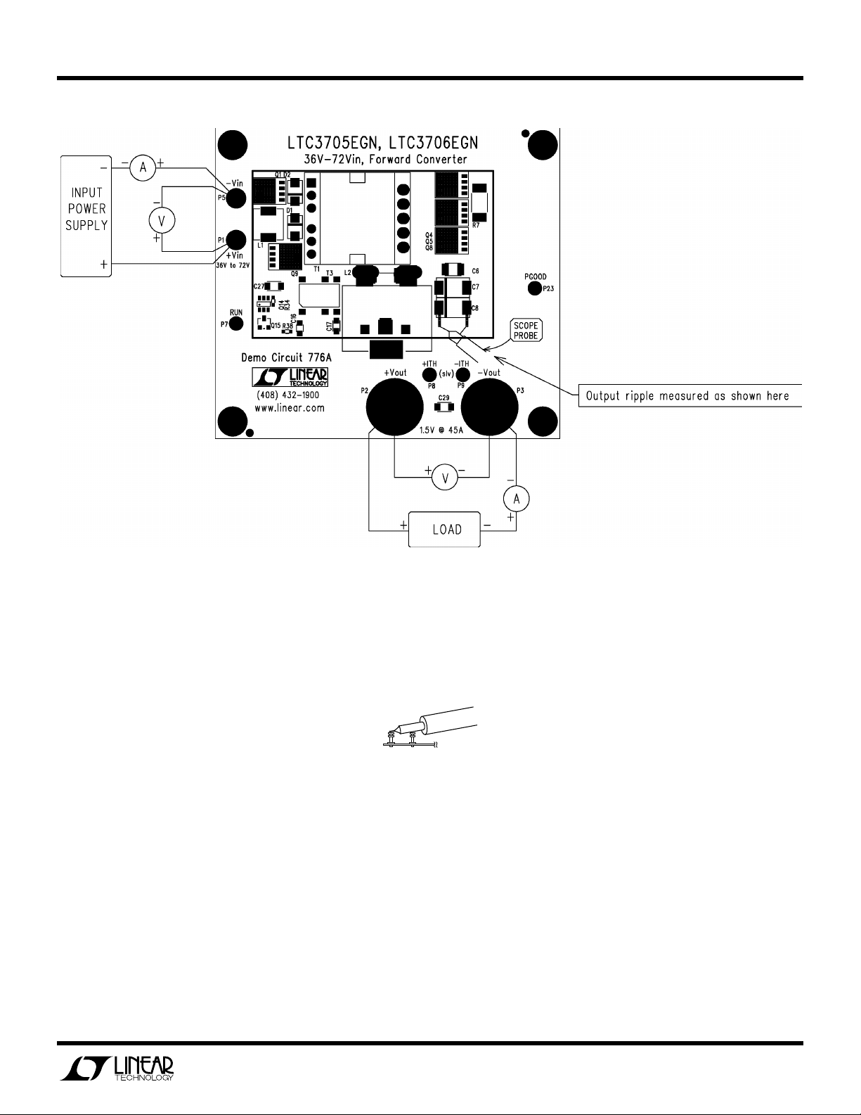
Refer to Figure 1 for proper measurement equipment
setup and follow the procedure below:
NOTE:
When measuring the input or output voltage
ripple, care must be taken to avoid a long ground lead
on the oscilloscope probe. Measure the output (or
input) voltage ripple by touching the probe tip and
probe ground directly across the +Vout and –Vout (or
+Vin and –Vin) terminals. See Figure 2 for proper
scope probe technique.
1.
Set an input power supply that is capable of 36V to
72V to a voltage of 36V. Then turn off the supply.
2.
With power off, connect the supply to the input
terminals +Vin and –Vin.
a.
Input voltages lower than 36V can keep the converter from turning on due to the undervoltage
lockout feature of the LTC3705.
b.
If efficiency measurements are desired, an ammeter capable of measuring 3Adc can be put in
series with the input supply in order to measure
the DC776A’s input current.
c.
A voltmeter with a capability of measuring at
least 72V can be placed across the input terminals in order to get an accurate input voltage
measurement.
reduces output capacitance. This, while utilizing offthe-shelf magnetics and attaining high efficiency.
For large values of input inductance, a 100V, 47uF electrolytic capacitor can be added across the input terminals to damp the input filter and provide adequate stability. See Linear Technology Application Note AN19 for a
discussion on input filter stability analysis. A recommended part is the Sanyo 100MV39AX.
NOTE:
Make sure that the input voltage never ex-
ceeds 72V.
4.
Check for the proper output voltage of 1.5V ± 1%.
Turn off the power at the input.
5.
Once the proper output voltages are established,
connect a variable load capable of sinking 50A at
1.5V to the output terminals +Vout and –Vout. Set
the current for 0A.
a.
If efficiency measurements are desired, an ammeter or a resistor shunt that is capable of handling 50Adc can be put in series with the output
load in order to measure the DC776A’s output
current.
b.
A voltmeter with a capability of measuring at
least 2V can be placed across the output terminals in order to get an accurate output voltage
measurement.
6.
Turn on the power at the input.
NOTE:
If there is no output, temporarily disconnect
the load to make sure that the load is not set too
high.
7.
Once the proper output voltage is again established, adjust the load within the operating range
and observe the output voltage regulation, ripple
voltage, efficiency and other desired parameters.
3.
Turn on the power at the input.
2
Page 3
QUICK START GUIDE FOR DEMONSTRATION CIRCUIT 776
VIN
GND
36V-72VIN, FORWARD CONVERTER
Figure 1. Proper Measurement Equipment Setup
Figure 2. Measuring Input or Output Ripple
3
Page 4
QUICK START GUIDE FOR DEMONSTRATION CIRCUIT 776
MEASURED DATA
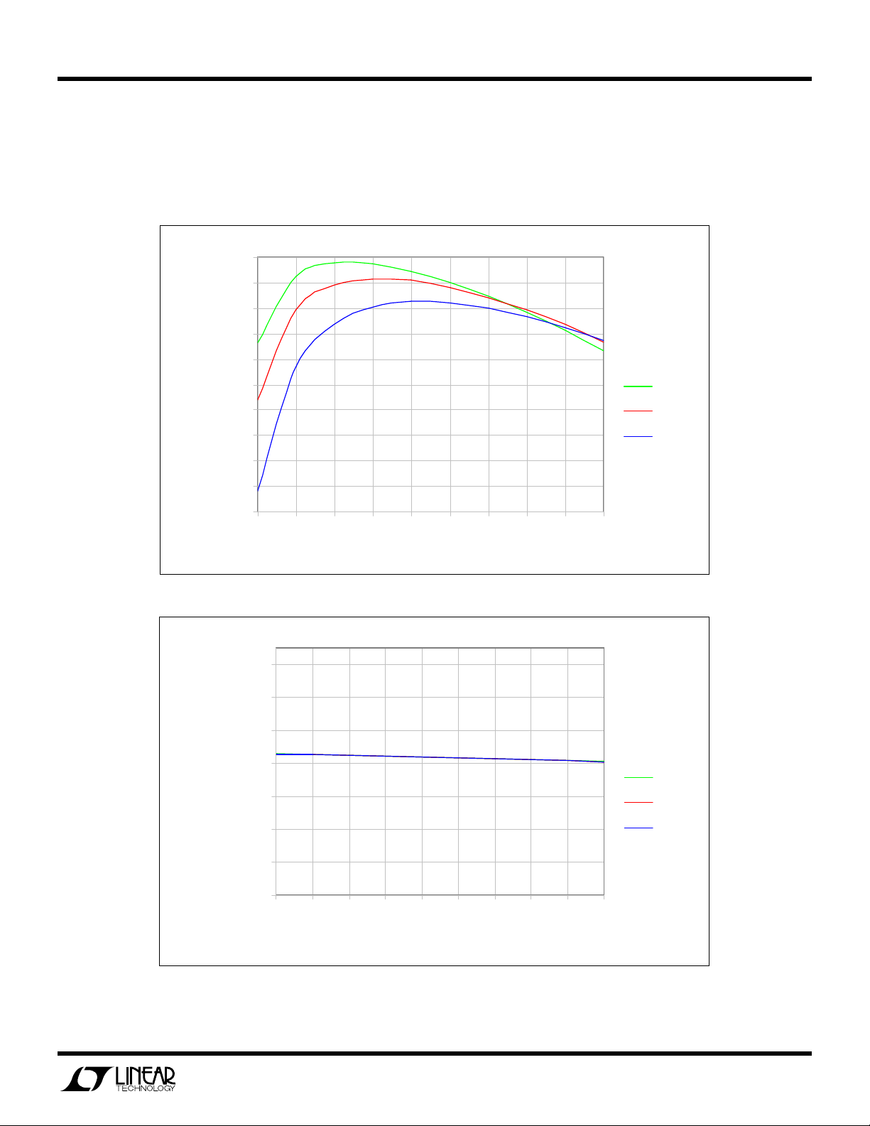
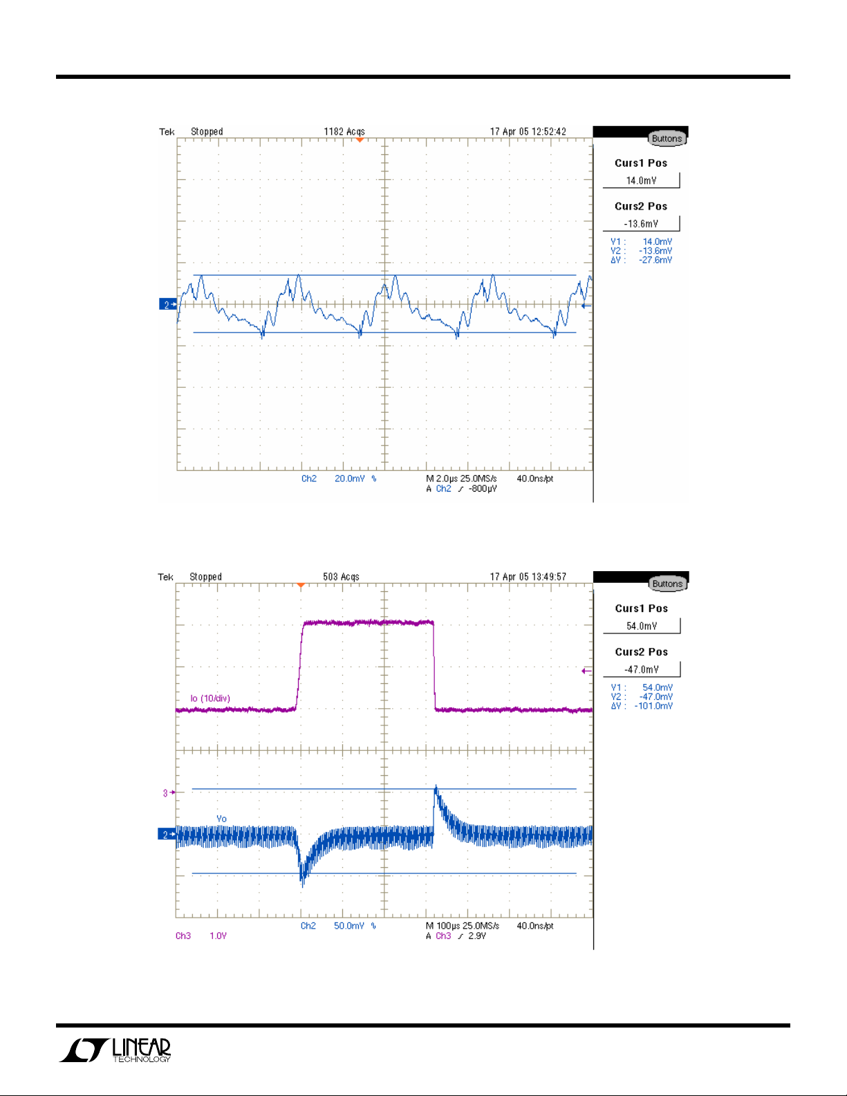
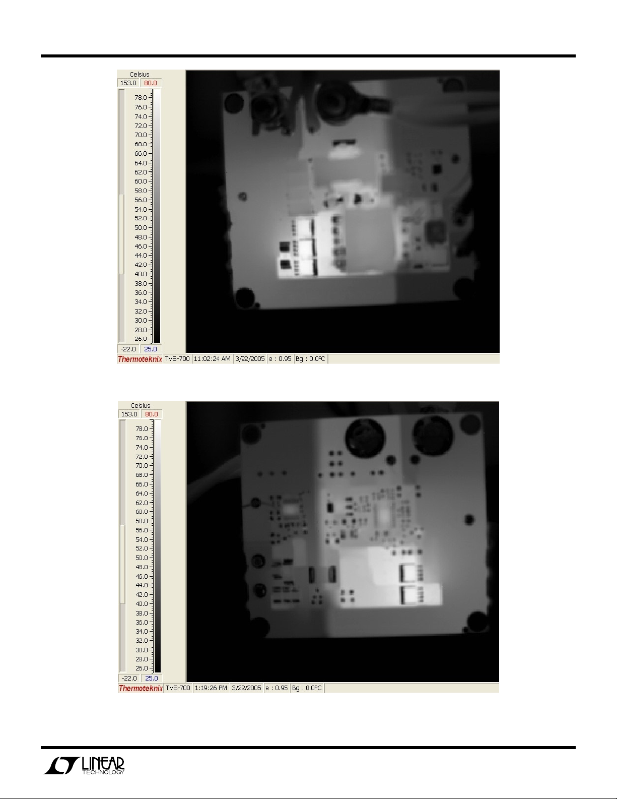
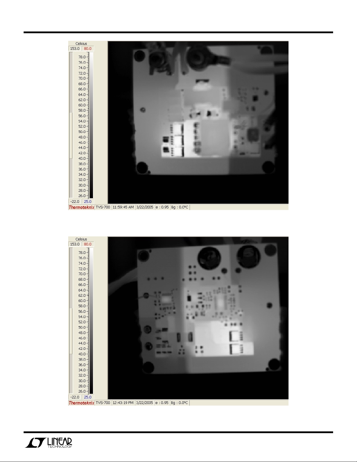
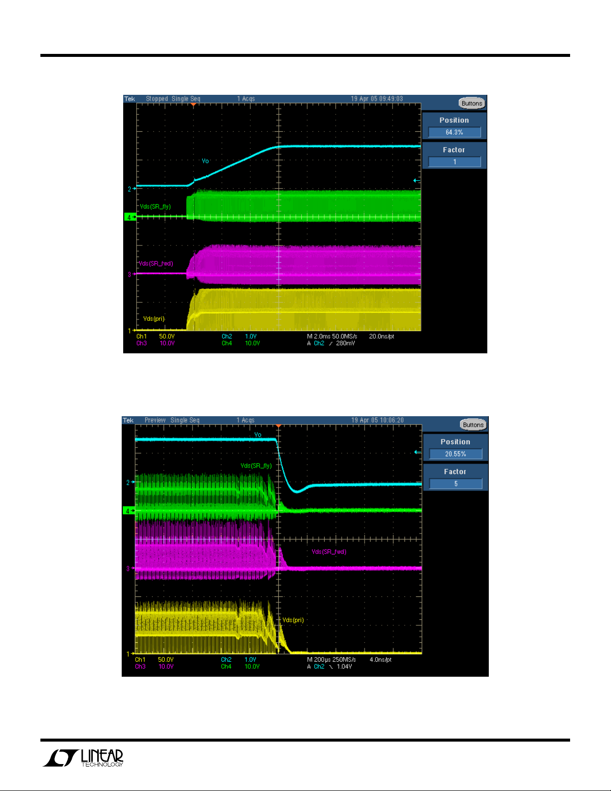
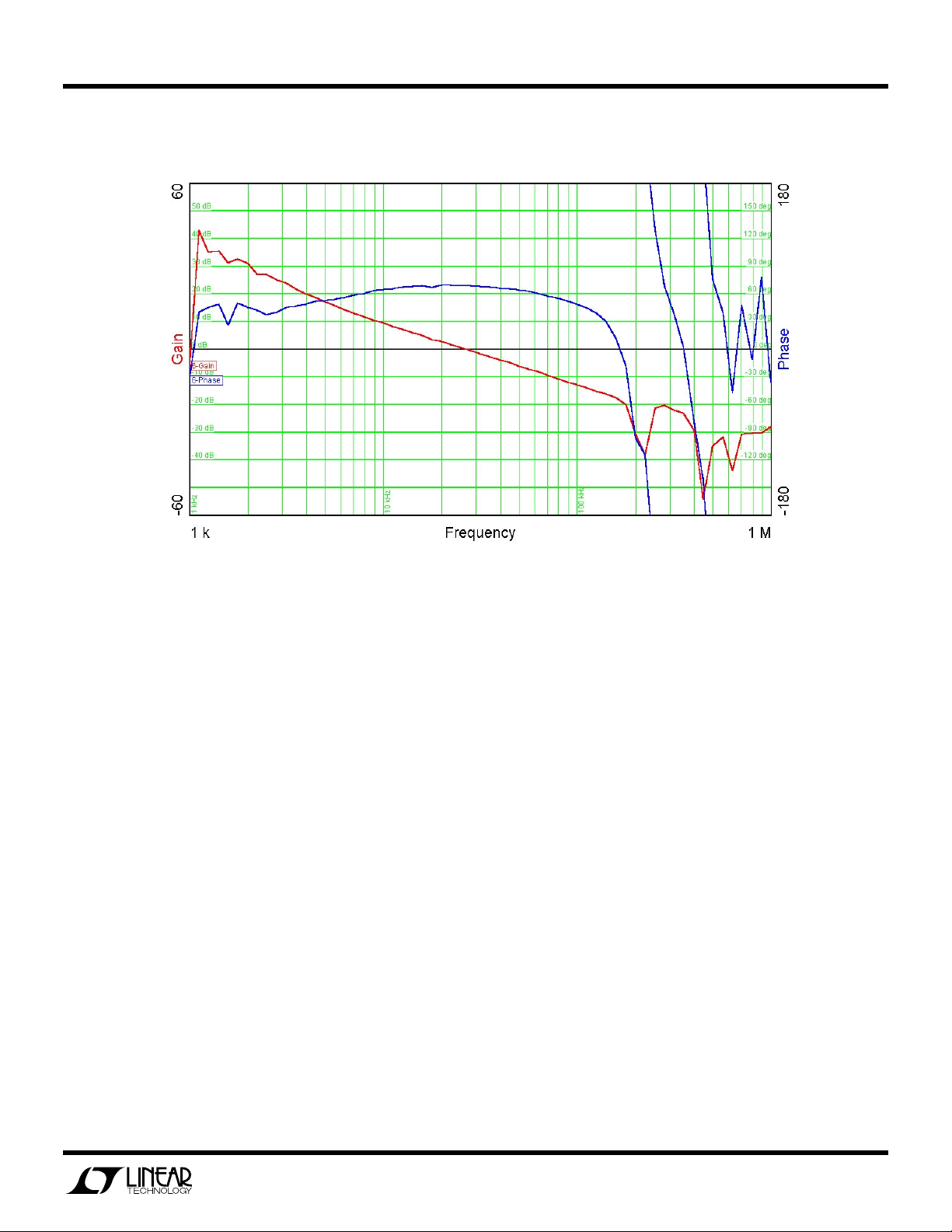
Figures 3 through 13 are measured data for a typical DC776A.
90
88
86
84
82
36V-72VIN, FORWARD CONVERTER
80
78
76
Efficiency (% )
74
72
70
5 10 15 20 25 3 0 35 40 45 50
36 VIN
48 VIN
72 VIN
Current (A)
Figure 3. Efficiency (400LFM)
1.5 6 5
1.5 4 5
1.5 2 5
1.5 0 5
1.4 8 5
Regulation (V)
1.4 6 5
1.4 4 5
36 VIN
48 VIN
72 VIN
1.4 2 5
5 10 15 20 25 30 35 40 45 50
Current (A)
Figure 4. Regulation (400LFM)
4
Page 5
QUICK START GUIDE FOR DEMONSTRATION CIRCUIT 776
36V-72VIN, FORWARD CONVERTER
Figure 5. Output Voltage Ripple (72Vin and 50A)
Figure 6. Load Transient Response (>1A/us)
5
Page 6
QUICK START GUIDE FOR DEMONSTRATION CIRCUIT 776
36V-72VIN, FORWARD CONVERTER
Figure 7. Temp Data (48Vin, 45A, 400LFM – front)
Figure 8. Temp Data (48Vin, 45A, 400LFM – back)
6
Page 7
QUICK START GUIDE FOR DEMONSTRATION CIRCUIT 776
36V-72VIN, FORWARD CONVERTER
Figure 9. Temp Data (48Vin, 40A, 200LFM – front)
Figure 10. Temp Data (48Vin, 40A, 200LFM – back)
7
Page 8
QUICK START GUIDE FOR DEMONSTRATION CIRCUIT 776
36V-72VIN, FORWARD CONVERTER
Figure 11. Turn-on Waveforms (72Vin and 50A)
Figure 12. Turn-off Waveforms (72Vin and 50A)
8
Page 9
QUICK START GUIDE FOR DEMONSTRATION CIRCUIT 776
36V-72VIN, FORWARD CONVERTER
Figure 13. Control Loop Bode Plot (48Vin and 20A)
9
Page 10
QUICK START GUIDE FOR DEMONSTRATION CIRCUIT 776
36V-72VIN, FORWARD CONVERTER
10
Page 11

Mouser Electronics
Authorized Distributor
Click to View Pricing, Inventory, Delivery & Lifecycle Information:
Analog Devices Inc.:
DC776A
 Loading...