

Page 1
DC503A DEMO BOARD QUICK START GUIDE
Description:
The DC503A demo circuit board is intended to demonstrate the capabilities of the LT5512
downconverting mixer IC for cable infrastructure applications.
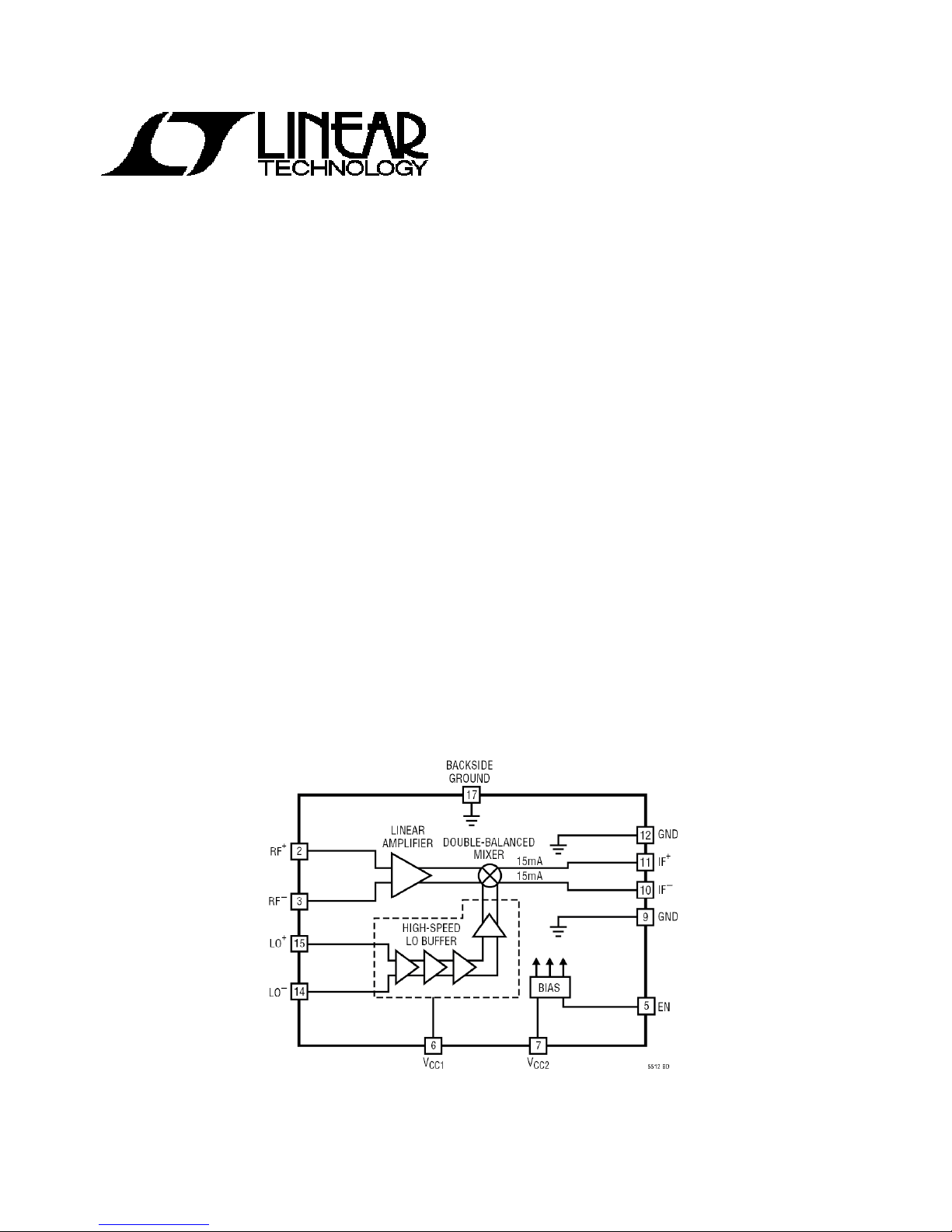
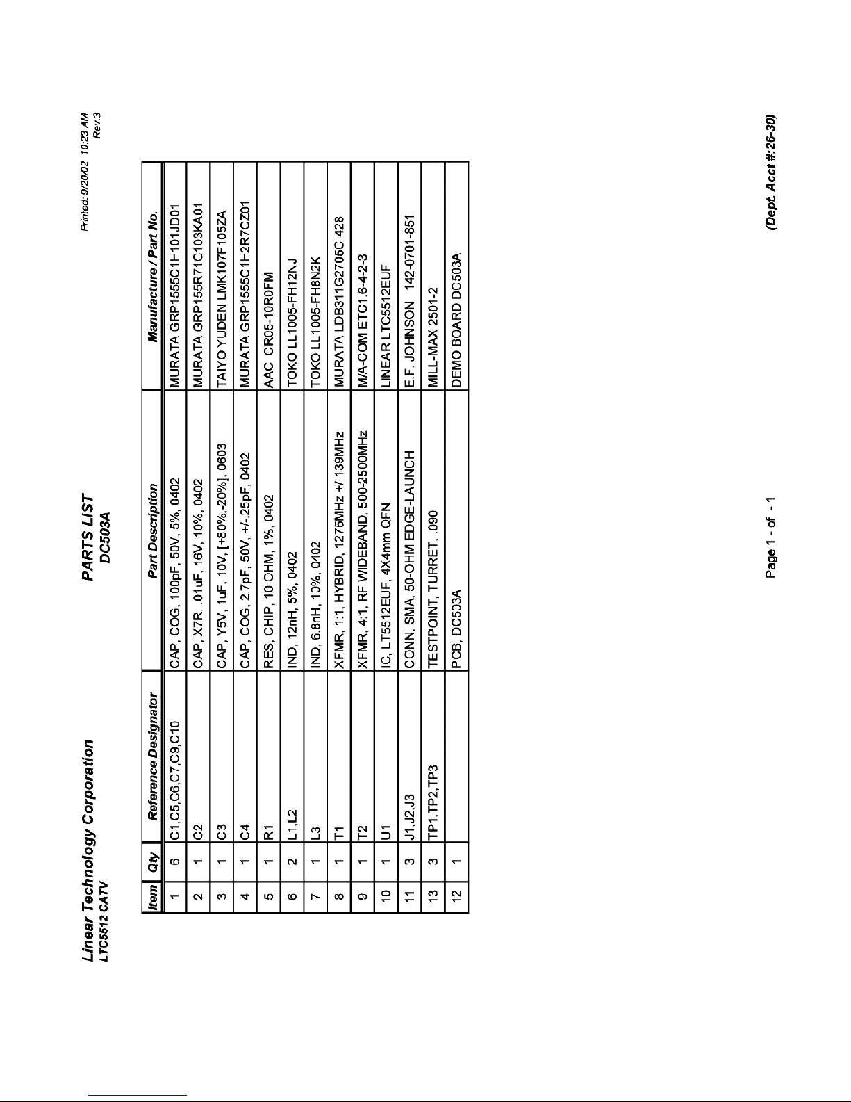
The LT5512 (Figure 1) is a broadband high signal level mixer IC optimized for high linearity
downconverter applications including cable and wireless infrastructure. The IC includes a
differential LO buffer driving a double-balanced mixer. An integrated RF amplifier improves LORF isolation and eliminates the need for precision external bias resistors.
The LT5512 is a high-linearity alternative to passive diode mixers. Unlike passive mixers, which
have conversion loss and require high LO drive level, the LT5512 delivers conversion gain and
requires significantly lower LO drive levels.
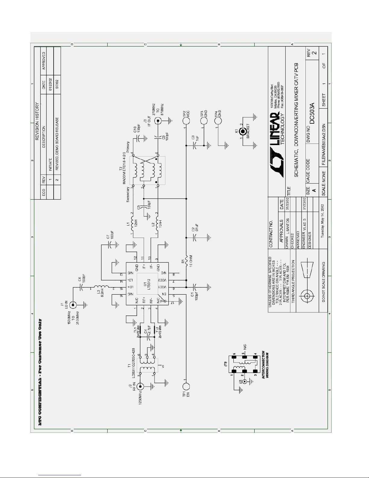
The DC503A demo board downconverts 1230MHz RF input to 270-870MHz IF output. The LO is
injected from the high-side between 1500MHz and 2100MHz.
Figure 1. LT5512 IC Block Diagram
1 of 11
Page 2
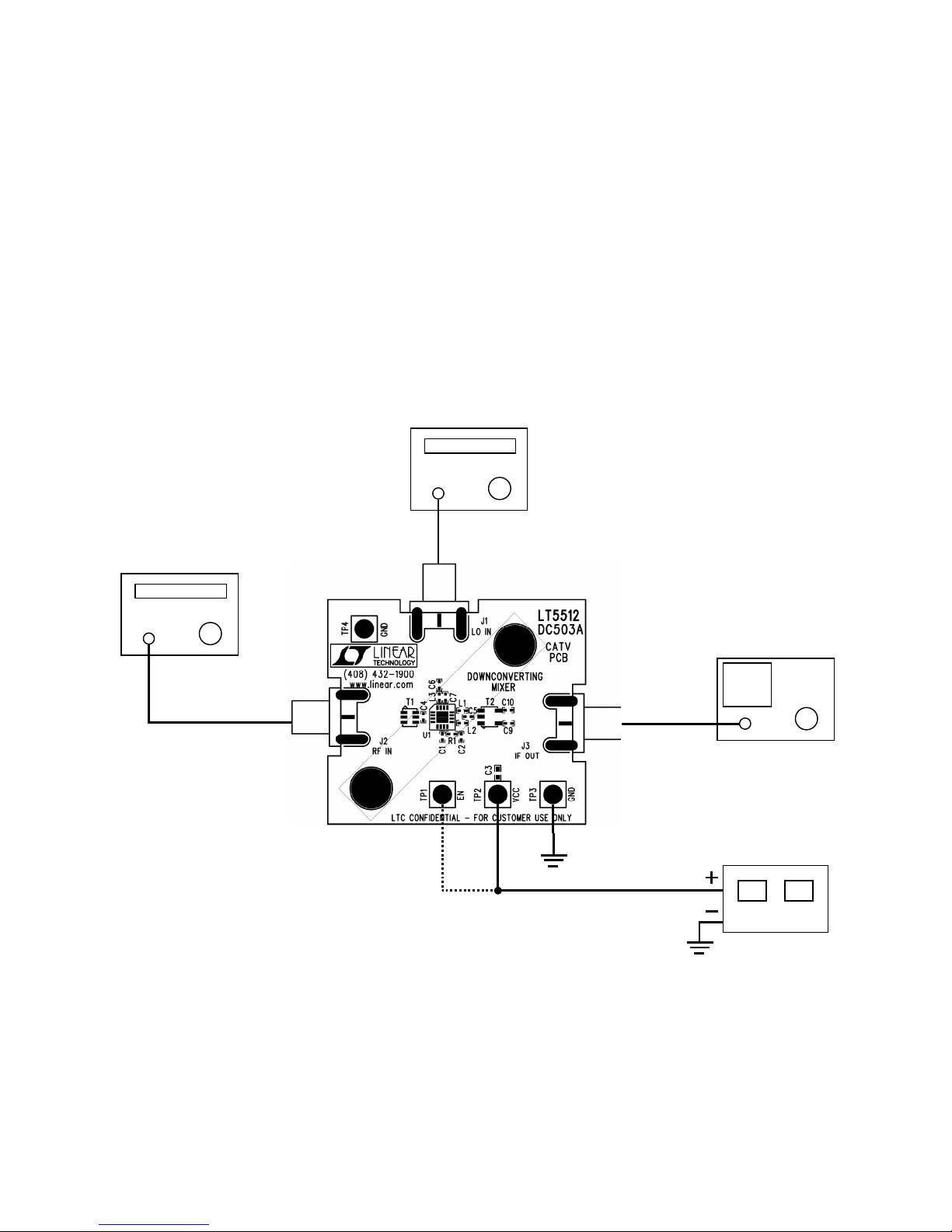
LT5512 Downconverting Mixer Single-Tone Measurements for 1230 MHz CATV Band.
1. Connect all test equipment as shown in Figure 2.
2. Set the Power Supply output voltage to 5V, and set the current limit to 100mA.
3. Connect TP1 (EN) to the 5V power supply. Mixer is in ENABLE mode.
4. Set the Signal Generator #1 to provide an 1800MHz, -10dBm, CW signal to the demo board
LOin port.
5. Set the Signal Generator #2 to provide a 1230MHz, -10dBm, CW signal to the demo board
RFin port.
6. Set the Spectrum Analyzer’s center frequency to 570MHz. Perform mixer conversion gain,
and 1dB compression measurements.
7. Set the Spectrum Analyzer’s center frequency to 1800MHz. Perform mixer LO to IF
leakage measurement.
SIGNAL
GENERATOR 2
SIGNAL
GENERATOR 1
SPECTRUM
ANALYZER
Figure 2. Test Set-Up for Mixer Single-Tone Measurements.
POWER SUPPLY
2 of 11
Page 3
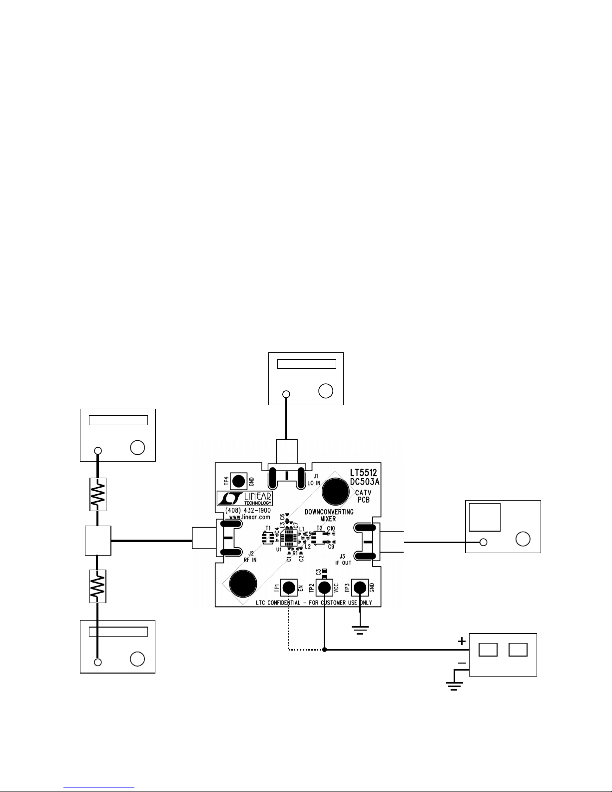
LT5512 Downconverting Mixer Two-Tone Measurements for 1230MHz CATV Band.
∑
1. Connect all test equipment as shown in Figure 3.
Note: 1). A high quality combiner that provides 50-ohm termination on all ports and has
good port-to-port isolation should be used.
2). The two 3dB attenuators on the inputs of the combiner are used to further
improve source isolation.
2. Set the Power Supply output voltage to 5V, and set the current limit to 100mA.
3. Connect TP1 (EN) to the 5V power supply. Mixer is in ENABLE mode.
4. Set the Signal Generator #1 to provide a 1800MHz, -10dBm, CW signal to the demo board
LOin port.
5. Set the Signal Generator #2 and #3 to provide two -10dBm CW signals to the demo board
RFin port—one at 1229.9MHz, and the other at 1230.1MHz.
6. Set the Spectrum Analyzer’s center frequency to 570MHz. Perform input 3rd order
distortion measurement. (IIP3 = P1 + (P1 – P3) / 2 – Gc, where P1 is the lowest power level
of the two desired output tones at either 569.9MHz or 570.1MHz, P3 is the largest 3rd order
product at either 569.7MHz or 570.3MHz, and Gc is conversion gain. P1 and P3 are in units
of dBm, and Gc is in dB.)
SIGNAL
GENERATOR 2
3dB PAD
3dB PAD
SIGNAL
GENERATOR 3
Figure 3. Test Set-Up for Mixer Two-Tone Measurements.
SIGNAL
GENERATOR 1
SPECTRUM
ANALYZER
POWER SUPPLY
3 of 11
Page 4
4 of 11
Page 5
5 of 11
Page 6

VENDOR
AAC (was TAD) (800) 508-1521 CHIP RESISTORS
AAC (was TAD) (714) 255-9186
AAVID (714) 556-2665 HEAT SINKS
ALLEN BRADLEY (800) 592-4888 CARBON RESISTORS
AMP (717) 564-0100 PC MOUNT BNC
APEM (718) 246-1007 SMD TOGGLE/PB SWITCH
API DELEVAN (716) 652-3600 INDUCTORS
AVX (843) 946-0362 CHIP CAPS
AVX (843) 946-0524 CHIP RESISTORS
AVX (207) 282-5111 TANTALUM CAPS
AVX (843) 946-0323 HIGH VOLTAGE CAPS
BERG (800) 237-2374 CONNECTORS
BH ELECTRONICS (952) 894-9590 INDUCTORS
BI TECHNOLOGIES (714) 447-2656 TRANSFORMERS
BI TECHNOLOGIES (714) 447-2345 RES./RES. NETWORKS
BOURNS (801) 750-7253 POTENTIOMETERS, SIPS
CADDOCK ELECTRONICS (541) 496-0700 HIPO. RES., SIPS, DIPS
CENTRAL SEMI (631) 435-1110 SMALL SIGNAL DISCRETES
CHICAGO MINIAT. LAMP (201) 489-8989 LEDS
COILCRAFT (847) 639-6400 INDUCTORS
COMM CON (626) 301-4200 HEADERS, SHUNTS
CONNEX (805) 378-6464 BNC CONNECTORS
COOPER ELECT. TECH. (561) 752-5000 INDUCTORS
CORNELL DUBILIER (508) 996-8561 CAPACITORS
CTS (219) 293-7511 RESISTOR ARRAYS
CUI-STACK (503) 643-4899 POWER CONNECTORS
DALE (see Vishay) (605) 665-1627 INDUCTORS
DALE (see Vishay) (605) 665-9301 SENSE RESISTORS
DATA DISPLAY PRODUCT (800) 421-6815 LEDS
DIODES INC. (805) 446-4800 DIODES
ELECTRONIC CONCEPTS (908) 542-7880 400V FILM CAPACITORS
EPSON (310) 787-6300 CRYSTALS
FAIRCHILD (207) 775-4502 LOGIC
FAIRCHILD (408) 822-2126 MOSFETS
FAIRCHILD (888) 522-5372 CRG (CUST. RESPONSE)
FCI (717) 767-8005 HOT PLUG CONNECTORS
FUKUSHIMA (818) 765-8300 MPC RESISTORS
FUJI (201) 712-0555 SCHOTTKY DIODES
GENERAL
SEMICONDUCTOR (516) 847-3000 DIODES
GOWANDA (716) 532-2234 INDUCTORS
GRAYHILL (708) 354-1040 DIP SWITCHES
HARRIS (800) 442-7747 LOGIC
HEWLETT PACKARD (800) 235-0312 IR LED
HITACHI (408) 433-1990 RF POWER AMPS
APPROVED VENDOR LIST
PHONE NUMBER PART TYPE WEBSITE ADDRESS
6 of 11
Page 7

IDT (408) 727-6116 LOGIC IC
IR (310) 322-3331 MOSFETS
IRC (361) 992-7900 SENSE RESISTORS
ITW PAKTRON (708) 667-3444 CAPACITORS
JOHNSON COMPONENTS (650) 948-6533 RF CONNECTORS
JOHNSON COMPONENTS (760) 434-5961 RF CONNECTORS
KEMET (408) 986-0424 TANTALUM CAPS
KEMET (864) 963-6300 CRG (CUST. RESPONSE)
KETEMA (714) 630-0081 SURGE SUPPRESSORS
KEYSTONE (718) 956-8900 JACKS, TURRETS
LITEON (408) 241-4588 LEDS, DIODES
LTC (408) 432-1900 HIGH PERF. I.C.S
MAGNETICS (800) 245-3984 TOROID CORES ETC.
MARCON (847) 696-2000 HIGH C/V CAPACITORS
METHODE (800) 323-6864 ZIF SOCKETS
MF ELECTRONICS (914) 576-6570 CRYSTAL OSCILLATORS
MICROCHIP (602) 786-7200 MICROCONTROLLER IC
MICRO PLASTICS (870) 453-8861 NYLON STANDOFFS
MICRO-SEMI (617) 926-0404 DIODES
MIDCOM (605) 886-4385 INDUCTORS
MIDCOM (800) 643-2661 INDUCTORS
MILL-MAX (516) 922-6000 TURRETS
MINICIRCUITS (718) 934-4500 RF TRANSFORMERS
MOTOROLA (800) 441-2447 LOGIC, REGS
MURATA ELECTRONICS (770) 436-1300 CAPS., INDUCTORS,
MURATA ELECTRONICS (800) 831-9172 CRG (CUST. RESPONSE)
MURATA ELECTRONICS (770) 433-5789 RF DEVICES
NEC/TOKIN (510) 324-4110 INDUCTORS/HI C/V CAPS
NICHIA (408) 573-0933 W HITE LEDS
NICHICON (847) 843-7500 ELECTROLYTIC CAPACITOR
ON SEMICONDUCTOR (602) 244-6600 DISCRETE DIODES ETC.
ON SHORE (602) 921-3000 TERMINATORS
PANASONIC (714) 373-7334 INDUCTORS, POLY CAPS
PANASONIC (201) 348-5217 LEDS
PANASONIC (201) 373-7334 SWITCHES
PERICOM (408) 435-0800 LOGIC IC
PHILIPS (914) 246-2811 INDUCTORS
PHILIPS (914) 247-2036 PLANAR INDUCTORS
PHILIPS (508) 851-2200 DISCRETES, I.C.s
PULSE (619) 674-8100 INDUCTORS
QT OPTOELECTRONICS (408) 720-1440 RF SWITCH
RAYCHEM (800) 227-4856 FUSES
RG ALLEN (818) 765-8300 METAL OXIDE RESISTORS
RF MICRO DEVICES (336) 664-1233 RF2138 / RF2140
SAMTEC (800) 726-8329 WIRE JUMPERS
SANYO (619) 661-6835 OSCON CAPS
SCHOTT (507) 532-3201 INDUCTORS, XFORMERS
SCHURTER (707) 778-6311 FUSES AND HOLDERS
7 of 11
Page 8

SIGNATRON (909) 464-1883 DB9 CONNECTORS
SIEMENS (108) 257-7910 OPTO
SILICONIX (800) 554-5565 MOSFETS
SILICONIX (408) 988-8000 MOSFETS
SPRAGUE (207) 324-4140 CAPACITORS
SULLINS (760) 744-0125 HEADERS, SHUNTS
SUMIDA (847) 956-0667 INDUCTORS
SUMIDA (408) 982-9660 INDUCTORS
TAIYO YUDEN (408) 573-4150 CHIP CAPS / RES.
TAIYO YUDEN (800) 348-2496 CRG (CUST. RESPONSE)
TEKTRONIX (800) 835-9433 SCOPE PROBE SOCKETS
TEMIC (408) 970-5700 IR PHOTO DIODE
THERMALLOY (972) 243-4321 HEAT SINKS
THIN FILM TECHNOLOGY (507) 625-8445 THIN FILM CHIP RESISTORS
TOCOS (847) 884-6664 SMD POTENTIOMETERS
TOKIN (NEC) (510) 324-4110 CAPS., INDUCTORS,
TOKO (847) 699-3430 RF PRODUCTS
TOSHIBA (714) 455-2000 SINGLE GATE LOGIC
TOSHIBA (949) 455-2000 LOGIC
UNITED CHEMICON (847) 696-2000 ELECTROLYTIC CAPACITOR
VISHAY (605) 665-9301 ZENER/SM. SIGNAL DIODES
VISHAY (605) 665-9301 INDUCTORS, SENSE Rs
VITRAMON (203) 268-6261 CERAMIC CHIP CAPACITOR
WIMA (914) 347-2474 PAPER/FILM CAPACITORS
ZETEX (631) 366-5068 SMALL SIGNAL DISCRETES
ZIERICK (800) 882-8020 STAKED PINS
8 of 11
Page 9
9 of 11
Page 10
10 of 11
Page 11
11 of 11
Page 12

Mouser Electronics
Authorized Distributor
Click to View Pricing, Inventory, Delivery & Lifecycle Information:
Analog Devices Inc.:
DC503A
 Loading...