

Page 1
DESCRIPTION
DEMO CIRCUIT 1345
QUICK START GUIDE
WIDE INPUT VOLTAGE RANGE
NO RSENSE STEP-DOWN DC/DC CONVERTER
LTC3879EMSE
Demonstration circuit 1345 is a wide input voltage
range, no Rsense step-down dc/dc converter featuring
the LTC3879EMSE. Its output voltage is 1.2V with a
load rating of 12A and the input voltage range is 4.5V
to 34V.
The fixed on-time valley current mode architecture of
the LTC3879EMSE provides a very fast load step response. Other features of the board include a RUN pin,
a TRACK pin, a PGOOD pin and a MODE jumper to
select either CCM or DCM operation at light load.
Design files for this circuit board are available. Call
the LTC factory.
Table 1. Performance Summary (TA = 25°C)
PARAMETER CONDITION VALUE
Minimum Input Voltage 4.5V
Maximum Input Voltage 34V
Output Voltage V
Maximum Output Current 12A
Typical Output Voltage Ripple VIN = 12V, I
Nominal Switching Frequency VIN = 12V, I
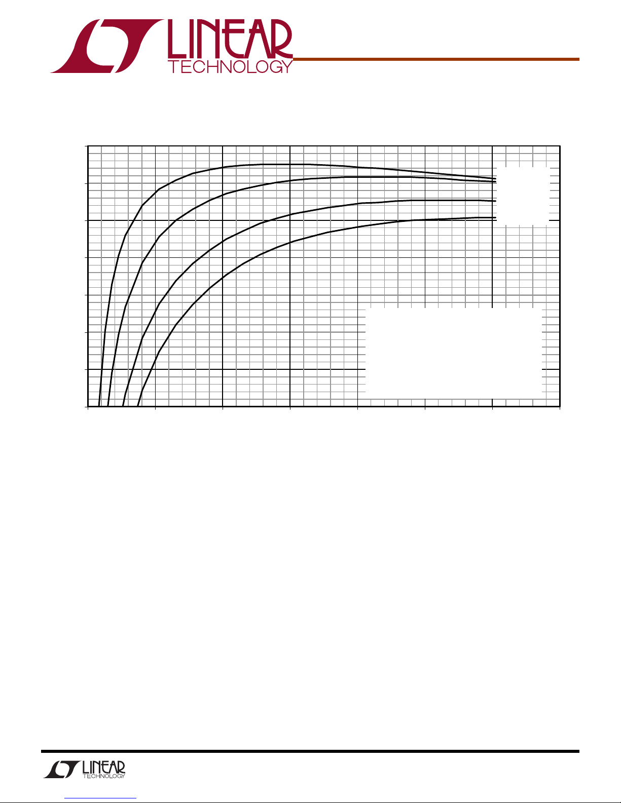
Efficiency (see Figure 3 for efficiency curves) VIN = 12V, I
VIN = 4.5V to 34V, I
OUT
= 0A to 12A 1.2V ±2%
OUT
= 12A (20MHz BW) 20mV
OUT
= 12A 300kHz
OUT
= 12A 90% Typical
OUT
P–P
QUICK START PROCEDURE
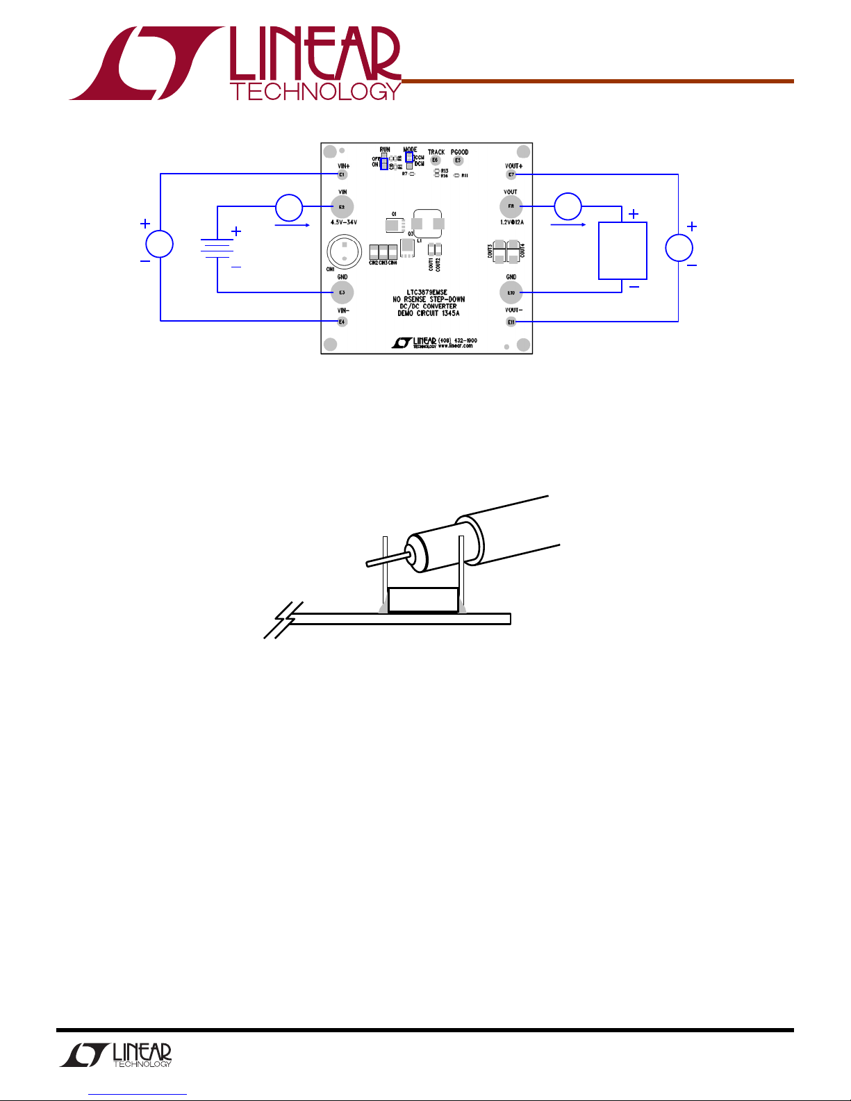
Demonstration circuit 1345 is easy to set up to evaluate the performance of the LTC3879EMSE. Refer to
Figure 1 for proper measurement equipment setup and
follow the procedure below:
NOTE:
must be taken to avoid a long ground lead on the oscilloscope probe. See Figure 2 for proper scope probe
technique. Short, stiff leads should be soldered to the
(+) and (-) terminals of an output capacitor. The
probe’s ground ring needs to touch the (-) lead and the
probe tip needs to touch the (+) lead.
When measuring the output voltage ripple, care
1.
Place jumpers in the following positions:
RUN ON
MODE CCM
2.
With power off, connect the input power supply to
Vin and GND.
3.
Turn on the power at the input.
4.
Check for the proper output voltages.
Vout = 1.176V to 1.224V
5.
Once the proper output voltages are established,
adjust the loads within the operating range and observe the output voltage regulation, ripple voltage,
efficiency and other parameters.
1
Page 2
DEMO CIRCUIT 1345
+
-
QUICK START GUIDE
Vin
Iout
A
Vout
Load
V
A
Iin
V
Vin
supply
Figure 1. Proper Measurement Equipment Setup
COUT
VOUT GND
Figure 2. Measuring Output Voltage Ripple
2
Page 3
95
DEMO CIRCUIT 1345
QUICK START GUIDE
Fsw = 300kHz, CCM
90
85
80
75
Efficiency
Parameters:
70
65
60
0 2 4 6 8 10 12 14
Load current (Amps)
Figure 3. Typical Efficiency Curves
QT = Infineon BSC093N04LSG
QB = Infineon BSC035N04LSG
L = Wurth 744325072
0.72uH, DCR=1.3mΩ +/- 10%
Ron = 576kΩ
Vin=5V
Vin=12V
Vin=24V
Vin=34V
3
Page 4
DEMO CIRCUIT 1345
QUICK START GUIDE
4
 Loading...