

Page 1
™
Advance Data Sheet
April 2000
D571-Type Digital 1.5 µ m Uncooled DFB
FastLight
■
Hermetically sealed active components
■
Internal back-facet monitor
■
Qualification program:
TA-983
*
T elcordia Technologies
Research, Inc.
is a trademark of Bell Communications
Laser Module
Telcordia T echnologies
*
Lucent
D571-10A
S/N-L651036
The low-profile D571-Type Laser Module is ideally suited for
short- and long-haul SONET and other high-speed digital
applications.
Features
■
Eight-pin package suitable for SONET/SDH
applications
■
Narrow linewidth, distributed-feedback, multiquantum-well (DFB-MQW), 1510 nm or 1550 nm laser
with single-mode fiber pigtail
■
Available in narrow and wide temperature ranges
■
No TEC required
■
High output power:
— Typical 2.0 mW peak power coupled into single-
mode fiber
— 1.0 mW devices are also available
Applications
■
Long-reach SONET OC-3/STM-1, OC-12/STM-4
systems
■
Telecommunications
■
Secure digital data systems
Benefits
■
Easily board mounted
■
Requires no lead bending
■
No additional heat sinks required
■
Pin compatible with industry-standard 14-pin laser
module
■
Highly efficient DFB-MQW laser structure allows
for lower threshold and drive currents , and reduced
power consumption
Description
The D571-T ype Uncooled Laser Module consists of a
laser diode coupled to a single-mode fiber pigtail.
The device is available in a standard, 8-pin configuration (see Figure 1 and/or Table 1) and is ideal for
long-reach (SONET) and other high-speed digital
applications.
The laser diode is a narrow linewidth (<1 nm) DFBMQW single-mode laser and an InGaAs PIN photodiode back-facet monitor in an epoxy-free, hermetically sealed package.
Page 2
±
°
°
D571-Type Digital 1.5 µ m Uncooled DFB Advance Data Sheet
FastLight
Laser Module April 2000
Description
(continued)
The device characteristics listed in this document are
met at 2.0 mW output power. Higher- or lower-power
operation is possible. Under conditions of a fixed photodiode current, the change in optical output is typically
0.5 dB over an operating temperature range of
–40 ° C to +85 ° C.
This device incorporates the new Laser 2000 manufac-
turing process developed by the Optoelectronic unit of
Lucent Technologies Microelectronics Group. Laser
2000 is a low-cost platform that targets high-volume
manufacturing and tighter product distributions on all
optical subassemblies. The platform incorporates an
advanced optical design that is produced on a highly
automated production line. The Laser 2000 platform is
43 12
56 87
qualified for the central office and uncontrolled environments, and can be used for applications requiring high
performance and low cost.
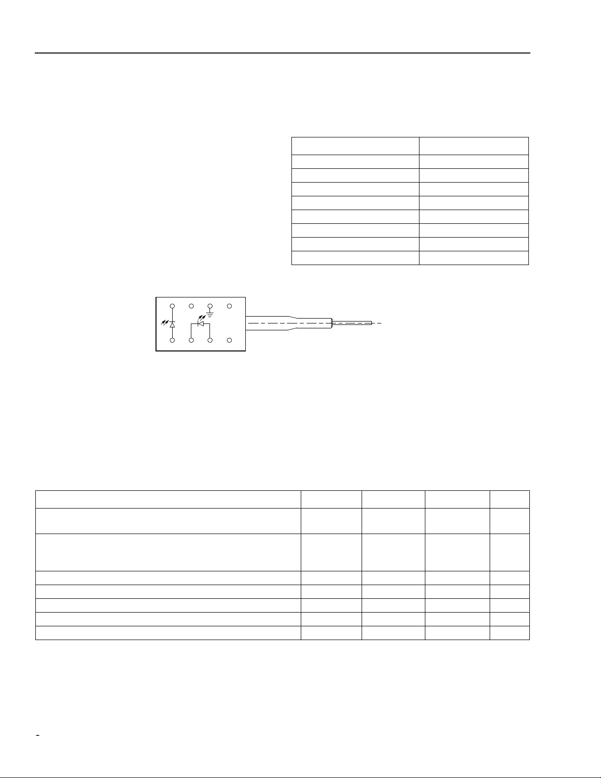
Table 1. Pin Descriptions
Pin Number Connection
1 NC/Reserved
2 Case ground
3 NC/Reserved
4 Photodiode cathode
5 Photodiode anode
6 Laser diode cathode
7 Laser diode anode
8 NC/Reserved
1-900 (C)
Figure 1. D571-Type Digital Uncooled DFB Flat-PAC Laser Module Schematic, Top View
Absolute Maximum Ratings
Stresses in excess of the absolute maximum ratings can cause permanent damage to the device. These are absolute stress ratings only. Functional operation of the device is not implied at these or any other conditions in excess
of those given in the operations sections of the data sheet. Exposure to absolute maximum ratings for extended
periods can adversely affect device reliability.
Parameter Symbol Min Max Unit
Maximum Peak Laser Drive Current or
Maximum Fiber Power*
Peak Reverse Laser Voltage:
Laser
Monitor
Monitor Forward Current I
Operating Case Temperature Range T
Storage Case Temperature Range T
Lead Soldering Temperature/Time —
Relative Humidity (noncondensing) RH — 85 %
* Rating varies with temperature.
P
I
V
V
OP
MAX
RL
RM
FD
C
stg
—
—
—
—
150
10
2
20
mA
mW
V
V
—2mA
–40 85
–40 85
C
C
— 260/10 ° C/s
22
Lucent Technologies Inc.
Page 3

°
∆λ
µ
Ω
µ
Advance Data Sheet D571-Type Digital 1.5 µ m Uncooled DFB
April 2000
FastLight
Laser Module
Handling Precautions
CAUTION: This device is susceptible to damage as a result of electrostatic discharge (ESD). Take proper
precautions during both handling and testing. Follow guidelines such as JEDEC Publication
No. 108-A (Dec. 1988).
Although protection circuitry is designed into the device, take proper precautions to avoid exposure to ESD.
Electro-Optical Characteristics
Table 2. Electro-Optical Characteristics (over operating temperature range unless otherwise noted)
Parameter Symbol Test Conditions Min Typ Max Unit
Operating Temperature
Range
Optical Output Power* P
Threshold Current I
Modulation Current I
Slope Efficiency
‡
Center Wav elength
Center Wav elength
1510 nm codes
Spectral Width (–20 dB)
Side-mode Suppression
Ratio
Tracking Error TE I
Spontaneous Emission P
Rise/Fall Times t
Forward Voltage V
Input Impedance R — 3 — 8
Monitor Current I
Monitor Dark Current I
Wav elength Tempera-
ture Coefficient
* 1mW power option also available. See Table 4 for more information.
† BOL value; EOL = 80 mA.
‡ The slope efficiency is used to calculate the modulation current for a desired output power. This modulation current plus the threshold current
comprise the total operating current for the device.
§ V
= reverse voltage.
R
T — –40 — 85
F
TH
MOD
CW, P
CW, nominal — 2 — mW
T = 25 ° C
T = full range
T = –10 ° C to + 70 ° C
= 2.0 mW, T = 25 ° C
F
CW, I
MON
= constant,
5
2
2
15
7.5
—
—
—
—
—
15
60
50
35
60
†
T = full range
SE CW, P
λ
C
λ
C
SMSR CW, P
TH
, t
R
F
F
= 2.0 mW, T = 25 ° C 57 — 133 µ W/mA
P
F
= 2.0 mW, CW 1525 — 1570 nm
P
= 2.0 mW, CW 1500 — 1520 nm
F
P
F
= 2.0 mW, 622 Mbits/s — — 1 nm
= 2.0 mW 30 40 — dB
F
MON
= constant, CW –1.5 — 1.5 dB
I = (0.9) I
TH
10%—90% pulse
— — 100
— 0.25 0.5 ns
T = 25 ° C
F
MON
D
CW — 1.1 1.6 V
§
V
= 5 V 100 — 1000
R
§
R
V
= 5 V — 10 200 nA
— — — 0.09 0.12 nm/ ° C
C
mA
mA
mA
mA
mA
W
A
Lucent Technologies Inc.
3
Page 4

1
(
)
D571-Type Digital 1.5 µ m Uncooled DFB Advance Data Sheet
FastLight
Laser Module April 2000
Outline Diagram
Dimensions are in inches and (millimeters)
TRADEMARK, CODE, LASER SERIAL NUMBER,
AND/OR DATE CODE IN APPROXIMATE AREA SHOWN
3
4
5678
21
0.52 (13.2)
1.06 (27.0)
MIN
39.37 (1000) MIN
PIGTAIL LENGTH
0.20 (5.00)
0.165 (4.20)
0.100 (2.54)
0.300
(7.62)
0.045 (1.143)
0.016 (0.410)
0.110 (2.79)
0.010
(0.254)
0.29
(7.37)
0.17
(4.32)
0.30
7.62
0.085
(2.16)
1-899.f
4
Lucent Technologies Inc.
Page 5

Advance Data Sheet D571-Type Digital 1.5 µ m Uncooled DFB
April 2000
FastLight
Laser Module
Qualification Information
The D571-Type Laser Module is scheduled to complete the following qualification tests and meets the intent of
T elcordia Technologies
ments.
Table 3. D571-Type Laser Module Qualification Test Plan
Qualification Test Conditions Sample Size Reference
Mechanical Shock
Vibration
Solderability
Thermal Shock
Fiber Pull
Accelerated (Biased) Aging
85 ° C Storage
Temperature Cycling
Cyclic Moisture Resistance
Damp Heat
Internal Moisture
Flammability
ESD Threshold
TR-NWT-000468 for interoffice en vironments and TA-TSY-000983 for outside plant environ-
500 G for P/F
1,500 G for information
20 g, 20 Hz—2,000 Hz
—
Delta T = 100 ° C
1 kg; 3 times for P/F
2 kg; 3 times for information
85 ° C, 5,000 hrs.
1,000 hrs. for provisional qual.
2,000 hrs. for P/F
5,000 hrs. for information
500 cycles for P/F
1,000 cycles for information
10 cycles for P/F
20 cycles for information
40 °C, 95% RH
1,000 hrs. for provisional qual.
1,344 hrs. for P/F
<5,000 ppm water vapor
—
—
11 MIL-STD-883
Method 2002
11 MIL-STD-883
Method 2007
11 MIL-STD-883
Method 2007
11 MIL-STD-883
Method 2003
11
25
11
11
11
11 MIL-STD-202
11 MIL-STD-883
— TR357
6
Telcordia T echnologies
Telcordia T echnologies
Section 5.18
Telcordia T echnologies
Telcordia T echnologies
Section 5.20
Telcordia T echnologies
Section 5.23
Method 103
Method 1018
Sec. 4.4.2.5
Telcordia T echnologies
Section 5.22
983
983
983
983
983
983
Lucent Technologies Inc.
5
Page 6

D571-Type Digital 1.5 µm Uncooled DFB Advance Data Sheet
FastLight
Laser Module April 2000
Laser Safety Information
Class IIIb Laser Product
FDA/CDRH Class IIIb laser product. All versions are Class IIIb laser products per CDRH, 21 CFR 1040 Laser
Safety requirements. All versions are Class IIIb laser products per
fied with the FDA under accession number 8720010.
This product complies with 21 CFR 1040.10 and 1040.11.
8.3/125 µm single-mode fiber pigtail and connector (optional)
Wavelength = 1.5 µm
Maximum power = 10 mW
Because of size constraints, laser safety labeling is not affixed to the module but attached to the outside of the
shipping carton.
Product is not shipped with power supply.
Caution: Use of controls, adjustments, and procedures other than those specified herein may result in
hazardous laser radiation exposure.
*
IEC
is a registered trademark of The International Electrotechnical Commission.
IEC
* 60825-1:1993. The device has been certi-
10 mW 1.5 µm
6
Lucent Technologies Inc.
Page 7

Advance Data Sheet D571-Type Digital 1.5 µm Uncooled DFB
April 2000
FastLight
Laser Module
Ordering Information
Table 4. Ordering Information
Operating Case
Device Code Comcode Pfiber Wavelength Connector*
D571-10A 108401118 1.0 mW 1550 nm SC-PC –40 to +85
D571-10F 108401068 1.0 mW 1550 nm FC-PC –40 to +85
D571-10N 108401142 1.0 mW 1550 nm none –40 to +85
D571-11A 108401159 1.0 mW 1550 nm SC-PC –10 to +70
D571-11F 108401175 1.0 mW 1550 nm FC-PC –10 to +70
D571-11N 108401191 1.0 mW 1550 nm none –10 to +70
D571-20A 108217068 2.0 mW 1550 nm SC-PC –40 to +85
D571-20F 108401217 2.0 mW 1550 nm FC-PC –40 to +85
D571-20N 108401233 2.0 mW 1550 nm none –40 to +85
D571-21A 108401241 2.0 mW 1550 nm SC-PC –10 to +70
D571-21F 108401266 2.0 mW 1550 nm SC-PC –10 to +70
D571-21N 108401282 2.0 mW 1550 nm none –10 to +70
D571C20A 108469743 2.0 mW 1510 nm SC-PC –40 to +85
D571C20F 108469768 2.0 mW 1510 nm FC-PC –40 to +85
D571C20N 108469784 2.0 mW 1510 nm none –40 to +85
D571C21A 108469792 2.0 mW 1510 nm SC-PC –10 to +70
D571C21F 108469818 2.0 mW 1510 nm FC-PC –10 to +70
D571C21N 108469834 2.0 mW 1510 nm none –10 to +70
* Connectors will meet
T elcordia Technologies
GR-326-CORE.
Temperature
Range (°C)
Lucent Technologies Inc.
7
Page 8

D571-Type Digital 1.5 µm Uncooled DFB Advance Data Sheet
FastLight
Laser Module April 2000
For additional information, contact your Microelectronics Group Account Manager or the following:
INTERNET: http://www.lucent.com/micro, or for Optoelectronics information, http://www.lucent.com/micro/opto
E-MAIL: docmaster@micro.lucent.com
N. AMERICA: Microelectronics Group, Lucent Technologies Inc., 555 Union Boulevard, Room 30L-15P-BA, Allentown, PA 18103
ASIA PACIFIC: Microelectronics Group, Lucent Technologies Singapore Pte. Ltd., 77 Science Park Drive, #03-18 Cintech III, Singapore 118256
CHINA: Microelectronics Group, Lucent Technologies (China) Co., Ltd., A-F2, 23/F, Zao Fong Universe Building, 1800 Zhong Shan Xi Road,
JAPAN: Microelectronics Group, Lucent Technologies Japan Ltd., 7-18, Higashi-Gotanda 2-chome, Shinagawa-ku, Tokyo 141, Japan
EUROPE: Data Requests: MICROELECTRONICS GROUP DATALINE: Tel. (44) 7000 582 368, FAX (44) 1189 328 148
Lucent Technologies Inc. reserves the right to make changes to the product(s) or information contained herein without notice. No liability is assumed as a result of their use or application. No
rights under any patent accompany the sale of any such product(s) or information.
Copyright © 2000 Lucent Technologies Inc.
All Rights Reserved
1-800-372-2447, FAX 610-712-4106 (In CANADA: 1-800-553-2448, FAX 610-712-4106)
Tel. (65) 778 8833, FAX (65) 777 7495
Shanghai 200233 P. R. China
Tel. (81) 3 5421 1600, FAX (81) 3 5421 1700
Technical Inquiries: OPTOELECTRONICS MARKETING: (44) 1344 865 900 (Ascot UK)
Tel. (86) 21 6440 0468, ext. 316, FAX (86) 21 6440 0652
FastLight
is a trademark of Lucent Technologies Inc.
April 2000
DS00-136OPTO (Replaces DS99-056LWP)
 Loading...