

Page 1
VERTICAL
TO
E8
RED BIAS
<21-B>
TO
E7
GRN BIAS
E5003
E5007
TP50
RED OUTPUT
TP24
194V
TECHNICAL TRAINING
Field Service Guide
0
1
0
1
0
1
0
1
0
1
0
1
0
1
0
1
1
0
0
1
0
1
0
1
1
0
0
1
1
0
0
1
0
1
0
1
0
1
1
0
1
1
0
0
0
1
1
0
1
1
0
0
1
0
1
0
0
1
0
1
1
1
0
1
0
1
0
1
1
0
FP400
MID
CP410
CP411
DP400
LP401
LP400
BP400
BP401
BP414
TP630
BP610
IP650
LP650
LP605
BL600
BH
BL660
BW004
BV
Watchdog
Circuit Area
CPS
2
0
4
P
B
BP010
BP130
BP120
TL010
BL200
BP011
LP050
LL008
PSD
BP150
BL035
BF001
TP020
BL500
IP080
LP020
BP005
BL111
BP501
BP500
BV001
G
Link
BK202
IR & Key Board
BR001
IR001
Gem Cam
IT600
DVI
DVI
Aud
IX400
Comp
1
BV500
IV400
IR006
Comp
GH GV RH RV
BW005
CAM
IV100
CVBS
SSB
IC040
s
s
u
B
I
C
E
1&2
T
BK270
IK201
IV300
IX300
S
2
Vid
BA002
r
e
n
u
T
n
i
a
M
BA010
r
e
n
u
T
d
n
o
c
e
S
Monitor
BW001 BW002
BA001
IA001
Out
IA900
IB101
R-CRT
IB201
Grn
IB301
Blue
Red
BB104
BB204
BB201
BB203
BB202
G-CRT
BB303
B-CRT
Page 2

Page 3

Sections
MODEL-TO-MAJOR ASSEMBLY CROSS REFERENCE........................... I
DISASSEMBLY........................................................................................... II
INTERCONNECT....................................................................................... III
VOL TAGE CHARTS................................................................................... Iv
WAVEFORMS............................................................................................. V
ALIGNMENT PROCEDURES....................................................................VI
ERROR CODES .......................................................................................VII
TROUBLESHOOTING FLOW CHARTS AND PROCEDURES .............. VIII
COMMON PARTS ORDERED...................................................................IX
IN-HOME SERVICE INFORMATION (Contact Phone Numbers)............IX
TECH-LINE INFORMATION .......................................................................X
MISC. INFORMATION ...............................................................................XI
CROSS REFERENCE CHARTS ...............................................................XI
BULLETINS (TTP, TV)...............................................................................XI
Page 4

Page 5

I
MODEL
-TO-
MAJOR
ASSEMBLY CROSS
REFERENCE
Page 6

MODEL-TO-MAJOR ASSEMBLY CROSS REFERENCE
KEY TO MAJOR ASSEMBLIES
IR1 - IR Receiver Board (10849310)
ADM1 - ATSC Tuner Board (10913610)
ADM2 - ATSC Tuner Board (10916570)
ADM3 - A TSC T uner Board (16655100)
CAB1 - Convergence Amplifier Board (10859730)
CAB2 - Convergence Amplifier Board (5609624Q)
CAB3 - Convergence Amplifier Board (5614795Q)
CONVP1 - Convergence Power Board (10803530)
CONVP2 - Convergence Power Board (5609624R)
CONVP3 - Convergence Power Board (5614795R)
CRT1 - CRT Driver Board 10840410)
CRT2 - CRT Driver Board (Red) (10859120)
CRT3 - CRT Driver Board (Green) (10859130)
CRT4 - CRT Driver Board (Blue) (10859140)
IR2 - IR Receiver Board (5609626T)
IR3 - IR Receiver Board (5609626Z)
LSC1 - Loud Speaker Connections (10849520)
MID1 - Mains Input Doubler (10849430)
PSD1 - Power Supply/Deflection PCB (10849230)
PSD2 - Power Supply/Deflection PCB (10849190)
PSD3 - Power Supply/Dynamic Focus (10859740)
PSD4 - Power Supply/Deflection PCB (10802090)
PSD5 - Power Supply/Deflection PCB (10920590)
PSD6 - Power Supply/Deflection PCB (1091 1450)
PSD7 - Power Supply/Deflection PCB (56096260)
PSD8 - Power Supply/Deflection PCB (5609626A)
CRTCl1 - CRT Driver Boards (56096250/A)
CRTCl2 - CRT Driver Boards (56147970/A)
DFB1 - Dynamic Focus Board (10773320)
DVD1 - DVD Assembly (21297430)
DVDIN- DVD Interface Board (10926930)
DVDIN2- DVD Interface Board (166551 10)
DVDPOWER1 - DVD Power Supply (10856500)
DVDPOWER2 - DVD Power Supply (5614795S)
DVDPOWER3 - DVD Power Supply (56190900)
ES1 - EchoStar SIP Module (10856130)
FCB1 - Front Connections Board (10849270)
FCB2 - Front Connections Board (10817610)
FCB3 - Front Connections Board (5609626R)
FCB4 - Front Connections Board (5609626W)
FPA1 - Front Panel Assembly (10849250)
FPA2 - Front Panel Assembly (10849220)
FPA3 - DVD Front Panel Assembly (10856510)
FPA4 - Front Panel Assembly (5609626S)
FPA5 - Front Panel Assembly (5609626Y)
SSB1 - Small Signal Board (10857000)
SSB2 - Small Signal Board (10862350)
SSB3 - Small Signal Board (10822270)
SSB4 - Small Signal Board (10918240)
SSB5 - Small Signal Board (10914030)
SSB6 - Small Signal Board (10914040)
SSB7 - Small Signal Board (10941320)
SSB8 - Small Signal Board (16654960)
SSB9 - Small Signal Board (16655010)
SSB10 - Small Signal Board (16555050)
SSB11 - Small Signal Board (16655060)
SSB12 - Small Signal Board (16655070)
SSB13 - Small Signal Board (16655080)
SSB14 - Small Signal Board (16655090)
SSB15 - Small Signal Board (10882720)
SSB16 - Small Signal Board (10889940)
I-1
Page 7

MODEL-TO-MAJOR ASSEMBLY CROSS REFERENCE
MODEL/
SERVICE NO.
D27F750TYX1 DV CRT1, FCB1, FPA2, MID1, PSD2, SSB2,
D32F750TYX1 DV CRT1, FCB1, FPA2, MID1, PSD2, SSB2,
D34W20BYX1 DV CRT1, DFB1, FCB1, FPA2, LSC1, MID1, PSD2, SSB2,
D34EW16YX1 DV CRT1, DFB1 ES1, FCB1, FPA2, LSC1, MID1, PSD2, SSB1,
D40EW11YX1 PTV CAB1, CRT2, CRT3, CRT4, ES1, FCB1, FPA1, IR1, LSC1, MID1, PSD1, PSD3, SSB1, CONVP1
D40EW16YX2 PTV CAB1, CRT2, CRT3, CRT4, ES1, FCB1, FPA1, IR1, LSC1, MID1, PSD1, PSD3, SSB1, CONVP1
D40EW16YX10 PTV CAB1, CRT2, CRT3, CRT4, ES1, FCB1, FPA1, IR1, LSC1, MID1, PSD1, PSD3, SSB1, CONVP1
D40EW21YX1 PTV CAB1, CRT2, CRT3, CRT4, ES1, FCB1, FPA1, IR1, LSC1, MID1, PSD1, PSD3, SSB1, CONVP1
D40W136DCYX1 PTV CAB1, CRT2, CRT3, CRT4, DVD1, DVD2, FCB1, FPA1, FPA3, IR1, LSC1,
MID1, PSD1, PSD3, SSB2, CONVP1
D40W15BYX1 PTV CAB1, CRT2, CRT3, CRT4, FCB1, FPA1, IR1, LSC1, MID1, PSD1, PSD3, SSB2, CONVP1
D40W15BYX2 PTV CAB1, CRT2, CRT3, CRT4, FCB1, FPA1, IR1, LSC1, MID1, PSD1, PSD3, SSB2, CONVP1
D40W15BYX10 PTV CAB1, CRT2, CRT3, CRT4, FCB1, FPA1, IR1, LSC1, MID1, PSD1, PSD3, SSB2, CONVP1
D40W17BYX1 PTV CAB1, CRT2, CRT3, CRT4, FCB1, FPA1, IR1, LSC1, MID1, PSD1, PSD3, SSB2, CONVP1
D40W17BYX2 PTV CAB1, CRT2, CRT3, CRT4, FCB1, FPA1, IR1, LSC1, MID1, PSD1, PSD3, SSB2, CONVP1
D40W17BYX10 PTV CAB1, CRT2, CRT3, CRT4, FCB1, FPA1, IR1, LSC1, MID1, PSD1, PSD3, SSB2, CONVP1
D40W20BYX1 PTV CAB1, CRT2, CRT3, CRT4, FCB1, FPA1, IR1, LSC1, MID1, PSD1, PSD3, SSB2, CONVP1
D40W20BYX2 PTV CAB1, CRT2, CRT3, CRT4, FCB1, FPA1, IR1, LSC1, MID1, PSD1, PSD3, SSB2, CONVP1
D40W20BYX10 PTV CAB1, CRT2, CRT3, CRT4, FCB1, FPA1, IR1, LSC1, MID1, PSD1, PSD3, SSB2, CONVP1
D52GW12BYX1 PTV CAB1, CRT2, CRT3, CRT4, FCB1, FPA1, IR1, LSC1, MID1, PSD1, PSD3, SSB2, CONVP1
D52GW12BYX10 PTV CAB1, CRT2, CRT3, CRT4, FCB1, FPA1, IR1, LSC1, MID1, PSD1, PSD3, SSB2, CONVP1
D52W131BYX1 PTV CAB1, CRT2, CRT3, CRT4, FCB1, FPA1, IR1, LSC1, MID1, PSD1, PSD3, SSB2, CONVP1
D52W136DBYX1 PTV CAB1, CRT2, CRT3, CRT4, DVD1, DVD2, FCB1, FPA1, FPA3, IR1, LSC1,
MID1, PSD1, PSD3, SSB2, CONVP1
D52W136DBYX2 PTV CAB1, CRT2, CRT3, CRT4, DVD1, DVD2, FCB1, FPA1, FPA3, IR1, LSC1,
MID1, PSD1, PSD3, SSB2, CONVP1
D52W136DBYX10 PTV CAB1, CRT2, CRT3, CRT4, DVD1, DVD2, FCB1, FPA1, FPA3, IR1, LSC1,
MID1, PSD1, PSD3, SSB2, CONVP1
D52W138DYX1 PTV CAB1 , CRT2, CRT3, CRT4, DVD1 , DV D2, FCB1, FPA1, FP A3, IR1, LSC1,
MID1, PSD1, PSD3, SSB2, CONVP1
D52W138DYX10 PTV CAB1, CRT2, CRT3, CRT4, DVD1, DVD2, FCB1, FPA1, FPA3, IR1, LSC1,
MID1, PSD1, PSD3, SSB2, CONVP1
D52GW12YX2 PTV CAB1, CRT2, CRT3, CRT4, FCB1, FPA1, IR1, LSC1, MID1, PSD1, PSD3, SSB2, CONVP1
CHASSIS MAJOR ASSEMBLIES
I-2
Page 8

MODEL-TO-MAJOR ASSEMBLY CROSS REFERENCE
MODEL/
SERVICE NO. CHASSIS MAJOR ASSEMBLIES
D52W14BYX1 PTV CAB1, CRT2, CRT3, CRT4, FCB1, FPA1, IR1, LSC1, MID1, PSD1, PSD3, SSB2, CONVP1
D52W14BYX10 PTV CAB1, CRT2, CRT3, CRT4, FCB1, FPA1, IR1, LSC1, MID1, PSD1, PSD3, SSB2, CONVP1
D52W14BYX2 PTV CAB1, CRT2, CRT3, CRT4, FCB1, FPA1, IR1, LSC1, MID1, PSD1, PSD3, SSB2, CONVP1
D52W14BYX38 PTV CAB2, CRTCL1, CONVP2, FCB4, FPA5, IR3, LSC1, MID1, PSD8, SSB10
D52W14BYX39 PTV CAB2, CRTCL2, CONVP2, FCB4, FPA5, IR3, LSC1, MID1, PSD8, SSB10
D52W15BYX1 PTV CAB1, CRT2, CRT3, CRT4, FCB1, FPA1, IR1, LSC1, MID1, PSD1, PSD3, SSB2, CONVP1
D52W15BYX2 PTV CAB1, CRT2, CRT3, CRT4, FCB1, FPA1, IR1, LSC1, MID1, PSD1, PSD3, SSB2, CONVP1
D52W15BYX10 PTV CAB1, CRT2, CRT3, CRT4, FCB1, FPA1, IR1, LSC1, MID1, PSD1, PSD3, SSB2, CONVP1
D52W17BYX1 PTV CAB1, CRT2, CRT3, CRT4, FCB1, FPA1, IR1, LSC1, MID1, PSD1, PSD3, SSB2, CONVP1
D52W17BYX2 PTV CAB1, CRT2, CRT3, CRT4, FCB1, FPA1, IR1, LSC1, MID1, PSD1, PSD3, SSB2, CONVP1
D52W17BYX10 PTV CAB1, CRT2, CRT3, CRT4, FCB1, FPA1, IR1, LSC1, MID1, PSD1, PSD3, SSB2, CONVP1
D52W17BYX20 PTV CAB1, CRT2, CRT3, CRT4, FCB1, FPA1, IR1, LSC1, MID1, PSD1, PSD3, SSB2, CONVP1
D52W19BYX1 PTV CAB1, CRT2, CRT3, CRT4, FCB1, FPA1, IR1, LSC1, MID1, PSD1, PSD3, SSB2, CONVP1
D52W19BYX2 PTV CAB1, CRT2, CRT3, CRT4, FCB1, FPA1, IR1, LSC1, MID1, PSD1, PSD3, SSB2, CONVP1
D52W19BYX5 PTV CAB1, CRT2, CRT3, CRT4, FCB1, FPA1, IR1, LSC1, MID1, PSD1, PSD3, SSB2, CONVP1
D52W19BYX10 PTV CAB1, CRT2, CRT3, CRT4, FCB1, FPA1, IR1, LSC1, MID1, PSD1, PSD3, SSB2, CONVP1
D52W19BYX20 PTV CAB1, CRT2, CRT3, CRT4, FCB1, FPA1, IR1, LSC1, MID1, PSD1, PSD3, SSB2, CONVP1
D52W19BYX22 PTV CAB1, CRT2, CRT3, CRT4, FCB1, FPA1, IR1, LSC1, MID1, PSD1, PSD3, SSB2, CONVP1
D52W19BYX30 PTV CAB1, CRT2, CRT3, CRT4, FCB1, FPA1, IR1, LSC1, MID1, PSD3, PSD4, SSB3, CONVP1
D52W19BYX31 PTV CAB1, CRT2, CRT3, CRT4, FCB1, FPA1, IR1, LSC1, MID1, PSD3, PSD4, SSB3, CONVP1
D52W19BYX32 PTV CAB1, CRT2, CRT3, CRT4, FCB1, FPA1, IR1, LSC1, MID1, PSD3, PSD6, SSB3, CONVP1
D52W19BYX38 PTV CAB2, CRTCL1, CONVP2, FCB4, FPA5, IR3, LSC1, MID1, PSD8, SSB8
D52W19BYX39 PTV CAB2, CRTCL2, CONVP2, FCB4, FPA5, IR3, LSC1, MID1, PSD8, SSB8
D52W19YX1 PTV CAB1, CRT2, CRT3, CRT4, FCB1, FPA1, IR1, LSC1, MID1, PSD1, PSD3, SSB2, CONVP1
D52W19YX10 PTV CAB1, CRT2, CRT3, CRT4, FCB1, FPA1, IR1, LSC1, MID1, PSD1, PSD3, SSB2, CONVP1
D52W19BYX20 PTV CAB1, CRT2, CRT3, CRT4, FCB1, FPA1, IR1, LSC1, MID1, PSD1, PSD3, SSB2, CONVP1
D52W19BYX30 PTV CAB1, CRT2, CRT3, CRT4, FCB1, FPA1, IR1, LSC1, MID1, PSD3, PSD4, SSB3, CONVP1
D52W19BYX31 PTV CAB1, CRT2, CRT3, CRT4, FCB1, FPA1, IR1, LSC1, MID1, PSD3, PSD4, SSB3, CONVP1
D52W19BYX32 PTV CAB1, CRT2, CRT3, CRT4, FCB1, FPA1, IR1, LSC1, MID1, PSD3, PSD5, SSB3, CONVP1
D52W20BYX5 PTV CAB1, CRT2, CRT3, CRT4, FCB1, FPA1, IR1, LSC1, MID1, PSD3, PSD4, SSB3, CONVP1
D52W23YX22 PTV CAB1, CRT2, CRT3, CRT4, FCB1, FPA1, IR1, MID1, PSD3, PSD6, SSB4, CONVP1
D52W23YX30 PTV CAB1, CRT2, CRT3, CRT4, FCB1, FPA1, IR1, MID1, PSD3, PSD4, SSB4, CONVP1
D52W23YX31 PTV CAB1, CRT2, CRT3, CRT4, FCB1, FPA1, IR1, MID1, PSD3, PSD4, SSB4, CONVP1
D52W23YX32 PTV CAB1, CRT2, CRT3, CRT4, FCB1, FPA1, IR1, MID1, PSD3, PSD6, SSB4, CONVP1
D52W23YX33 PTV CAB1, CRT2, CRT3, CRT4, FCB1, FPA1, IR1, MID1, PSD3, PSD6, SSB4, CONVP1
D52W23YX38 PTV CAB2, CRTCL1, CONVP2, FCB4, FPA5, IR3, LSC1, MID1, PSD8, SSB13
D52W23YX39 PTV CAB2, CRTCL2, CONVP2, FCB4, FPA5, IR3, LSC1, MID1, PSD8, SSB13
D52W23YX50 PTV CAB1, CRT2, CRT3, CRT4, FCB1, FPA1, IR1, MID1, PSD3, PSD4, SSB4, CONVP1
D52W23YX51 PTV CAB1, CRT2, CRT3, CRT4, FCB1, FPA1, IR1, MID1, PSD3, PSD4, SSB4, CONVP1
I-3
Page 9

MODEL-TO-MAJOR ASSEMBLY CROSS REFERENCE
MODEL/
SERVICE NO. CHASSIS MAJOR ASSEMBLIES
D52W25YX1 PTV CAB1, CRT2, CRT3, CRT4, FCB1, FPA1, IR1, MID1, PSD1, PSD3, SSB2, CONVP1
D52W25YX10 PTV CAB1, CRT2, CRT3, CRT4, FCB1, FPA1, IR1, MID1, PSD1, PSD3, SSB2, CONVP1
D52W25YX38 PTV CAB2, CRTCL1, CONVP2, FCB4, FPA5, IR3, LSC1, MID1, PSD8, SSB10
D52W25YX39 PTV CAB2, CRTCL2, CONVP2, FCB4, FPA5, IR3, LSC1, MID1, PSD8, SSB10
D52W26BYX1 PTV CAB1, CRT2, CRT3, CRT4, FCB1, FPA1, IR1, MID1, PSD1, PSD3, SSB2, CONVP1
D52W26BYX10 PTV CAB1, CRT2, CRT3, CRT4, FCB1, FPA1, IR1, MID1, PSD1, PSD3, SSB2, CONVP1
D52W26YX2 PTV CAB1, CRT2, CRT3, CRT4, FCB1, FPA1, IR1, MID1, PSD1, PSD3, SSB2, CONVP1
D52W26YX30 PTV CAB1, CRT2, CRT3, CRT4, FCB1, FPA1, IR1, MID1, PSD3, PSD4, SSB5, CONVP1
D52W26YX31 PTV CAB1, CRT2, CRT3, CRT4, FCB1, FPA1, IR1, MID1, PSD3, PSD4, SSB5, CONVP1
D52W26YX32 PTV CAB2, CRTCL1, CONVP2, FCB3, FP A4, IR2, MID1, PSD7, SSB16
D52W26YX33 PTV CAB2, CRTCL2, CONVP2, FCB3, FP A4, IR2, MID1, PSD7, SSB16
D52W26YX35 PTV CAB2, CRTCL1, CONVP2, FCB3, FP A4, IR2, MID1, PSD7, SSB16
D52W26YX36 PTV CAB2, CRTCL2, CONVP2, FCB3, FP A4, IR2, MID1, PSD7, SSB16
D52W26YX38 PTV CAB2, CRTCL1, CONVP2, FCB4, FP A5, IR3, MID1, PSD8, SSB10
D52W26YX39 PTV CAB2, CRTCL2, CONVP2, FCB4, FP A5, IR3, MID1, PSD8, SSB10
D52W27DYX1 PTV CAB1, CRT2, CRT3, CRT4, DVD1, DVD2, FCB1, FPA1, FPA3, IR1
MID1, PSD1, PSD3, SSB2, CONVP1
D52W27DYX2 PTV CAB1, CRT2, CRT3, CRT4, DVD1, DVD2, FCB1, FPA1, FPA3, IR1,
MID1, PSD1, PSD3, SSB2, CONVP1
D52W27DYX10 PTV CAB1, CRT2, CRT3, CRT4, DVD1, DVD2, FCB1, FPA1, FPA3, IR1,
MID1, PSD1, PSD3, SSB2, CONVP1
D52W27DYX22 PTV CAB1, CRT2, CRT3, CRT4, DVD1, DVD2, FCB1, FPA1, FPA3, IR1,
MID1, PSD3, PSD5, SSB2, CONVP1
D52W27DYX23 PTV CAB1, CRT2, CRT3, CRT4, DVD1, DVD2, FCB1, FPA1, FPA3, IR1,
MID1, PSD3, PSD6, SSB15, CONVP1
D52W27DYX32 PTV CAB3, CRTCL1, CONVP3, DVDPOWER2, FCB3, FPA4, FPA3, IR2,
MID1, PSD7, SSB15
D52W27DYX33 PTV CAB3, CRTCL2, CONVP3, DVDPOWER2, FCB3, FPA4, FPA3, IR2,
MID1, PSD7, SSB15
D52W27DYX35 PTV CAB3, CRTCL1, CONVP3, DVDPOWER2, FCB3, FPA4, FPA3, IR2,
MID1, PSD7, SSB15
D52W27DYX38 PTV CAB3, CRTCL1, CONVP3, DVDPOWER3, FCB4, FPA5, FPA3, IR3,
MID1, PSD8, SSB9
D52W27DYX39 PTV CAB3, CRTCL2, CONVP3, DVDPOWER3, FCB4, FPA5, FPA3, IR3,
MID1, PSD8, SSB9
D56W136DBYX1 PTV CAB1, CRT2, CRT3, CRT4, DVD1, DVD2, FCB1, FPA1, FPA3, IR1, LSC1,
MID1, PSD1, PSD3, SSB2, CONVP1
D56W136DBYX2 PTV CAB1, CRT2, CRT3, CRT4, DVD1, DVD2, FCB1, FPA1, FPA3, IR1, LSC1,
MID1, PSD1, PSD3, SSB2, CONVP1
D56W136DBYX1
MID1, PSD1, PSD3, SSB2, CONVP1
PTV CAB1, CRT2, CRT3, CRT4, DVD1, DVD2, FCB1, FP A1, FPA3, IR1, LSC1,
I-4
Page 10

MODEL-TO-MAJOR ASSEMBLY CROSS REFERENCE
MODEL/ SERVICE NO.
D56W20BYX1 PTV CAB1, CRT2, CRT3, CRT4, FCB1, FPA1, IR1, LSC1, MID1, PSD1, PSD3, SSB2, CONVP1
D56W20BYX2 PTV CAB1, CRT2, CRT3, CRT4, FCB1, FPA1, IR1, LSC1, MID1, PSD1, PSD3, SSB2, CONVP1
D56W20BYX10 PTV CAB1, CRT2, CRT3, CRT4, FCB1, FPA1, IR1, LSC1, MID1, PSD1, PSD3, SSB2, CONVP1
D61W136DBYX1 PTV CAB1, CRT2, CRT3, CRT4, DVD1, DVD2, FCB1, FPA1, FPA3, IR1, LSC1,
MID1, PSD1, PSD3, SSB2, CONVP1
D61W136DBYX2 PTV CAB1, CRT2, CRT3, CRT4, DVD1, DVD2, FCB1, FPA1, FPA3, IR1, LSC1,
MID1, PSD1, PSD3, SSB2, CONVP1
D61W136DBYX10 PTV CAB1, CRT2, CRT3, CRT4, DVD1, DVD2, FCB1, FPA1, FPA3, IR1, LSC1,
MID1, PSD1, PSD3, SSB2, CONVP1
D61W20BYX1 PTV CAB1, CRT2, CRT3, CRT4, FCB1, FPA1, IR1, LSC1, MID1, PSD1, PSD3, SSB2, CONVP1
D61W20BYX2 PTV CAB1, CRT2, CRT3, CRT4, FCB1, FPA1, IR1, LSC1, MID1, PSD1, PSD3, SSB2, CONVP1
HD52W59YX2 PTV CAB1, CRT2, CRT3, CRT4, FCB1, FPA1, IR1, MID1, PSD1, PSD3, SSB5, ADM1, CONVP1
HD52W59YX8 PTV CAB1, CRT2, CRT3, CRT4, FCB1, FPA1, IR1, MID1, PSD5, PSD3, SSB5, ADM2, CONVP1
HD52W59YX10 PTV CAB1, CRT2, CRT3, CRT4, FCB1, FPA1, IR1, MID1, PSD1, PSD3, SSB5, ADM1, CONVP1
HD52W59YX20 PTV CAB1, CRT2, CRT3, CRT4, FCB1, FPA1, IR1, MID1, PSD1, PSD3, SSB5, ADM2, CONVP1
HD52W59YX22 PTV CAB1, CRT2, CRT3, CRT4, FCB1, FPA1, IR1, MID1, PSD3, PSD5, SSB5, ADM2, CONVP1
HD52W59YX23 PTV CAB1, CRT2, CRT3, CRT4, FCB1, FPA1, IR1, MID1, PSD3, PSD5, SSB5, ADM2, CONVP1
HD52W59YX30 PTV CAB1, CRT2, CRT3, CRT4, FCB1, FPA1, IR1, MID1, PSD3, PSD4, SSB5, ADM2, CONVP1
HD52W59YX31 PTV CAB1, CRT2, CRT3, CRT4, FCB1, FPA1, IR1, MID1, PSD3, PSD4, SSB5, ADM2, CONVP1
HD52W59YX32 PTV CAB1, CRTCL1, FCB1, FPA1, IR1, MID1, PSD3, PSD6, SSB5, ADM2, CONVP1
HD52W59YX33 PTV CAB2, CRTCL2, CONVP2, FCB3, FPA4, IR2, MID1, PSD3, PSD7, SSB5, ADM2
HD52W59YX35 PTV CAB2, CRTCL1 CONVP2, FCB3, FPA4, IR2, MID1, PSD3, PSD7, SSB5, ADM2
HD52W59YX36 PTV CAB2, CRTCL2 CONVP2, FCB3, FPA4, IR2, MID1, PSD3, PSD7, SSB5, ADM2
HD52W59YX38 PTV CAB3, CRTCL1 CONVP3, FCB4, FPA5, IR3, MID1, PSD3, PSD8, SSB11, ADM3
HD52W59YX39 PTV CAB3, CRTCL2 CONVP3, FCB4, FPA5, IR3, MID1, PSD3, PSD8, SSB11, ADM3
HD52W59YX50 PTV CAB1, CRT2, CRT3, CRT4, FCB1, FPA1, IR1, MID1, PSD1, PSD3, SSB5, ADM2, CONVP1
HD52W59YX51 PTV CAB1, CRT2, CRT3, CRT4, FCB1, FPA1, IR1, MID1, PSD1, PSD3, SSB5, ADM2, CONVP1
HD52W64YX2 PTV CAB1, CRT2, CRT3, CRT4, FCB1, FPA1, IR1, MID1, PSD1, PSD3, SSB5, ADM1, CONVP1
HD52W64YX10 PTV CAB1, CRT2, CRT3, CRT4, FCB1, FPA1, IR1, MID1, PSD1, PSD3, SSB5, ADM1, CONVP1
HD52W64YX20 PTV CAB1, CRT2, CRT3, CRT4, FCB1, FPA1, IR1, MID1, PSD1, PSD3, SSB5, ADM2, CONVP1
HD52W64YX38 PTV CAB3, CRTCL1 CONVP3, FCB4, FPA5, IR3, MID1, PSD3, PSD8, SSB11, ADM3
HD52W64YX39 PTV CAB3, CRTCL2 CONVP3, FCB4, FPA5, IR3, MID1, PSD3, PSD8, SSB11, ADM3
HD52W65YX2 PTV CAB1, CRT2, CRT3, CRT4, FCB1, FPA1, IR1, MID1, PSD1, PSD3, SSB5, ADM1, CONVP1
HD52W65YX10 PTV CAB1, CRT2, CRT3, CRT4, FCB1, FPA1, IR1, MID1, PSD1, PSD3, SSB5, ADM1, CONVP1
HD52W65YX20 PTV CAB1, CRT2, CRT3, CRT4, FCB1, FPA1, IR1, MID1, PSD1, PSD3, SSB5, ADM2, CONVP1
HD52W65YX38 PTV CAB3, CRTCL1 CONVP3, FCB4, FPA5, IR3, MID1, PSD3, PSD8, SSB11, ADM3
HD52W65YX39 PTV CAB3, CRTCL2 CONVP3, FCB4, FPA5, IR3, MID1, PSD3, PSD8, SSB11, ADM3
HD52W66YX2 PTV CAB1, CRT2, CRT3, CRT4, FCB1, FPA1, IR1, MID1, PSD1, PSD3, SSB5, ADM1, CONVP1
HD52W66YX10 PTV CAB1, CRT2, CRT3, CRT4, FCB1, FPA1, IR1, MID1, PSD1, PSD3, SSB5, ADM1, CONVP1
HD52W66YX20 PTV CAB1, CRT2, CRT3, CRT4, FCB1, FPA1, IR1, MID1, PSD1, PSD3, SSB5 ADM2, CONVP1
HD52W66YX30 PTV CAB1, CRT2, CRT3, CRT4, FCB1, FPA1, IR1, MID1, PSD3, PSD4, SSB6 ADM2, CONVP1
HD52W66YX31 PTV CAB1, CRT2, CRT3, CRT4, FCB1, FPA1, IR1, MID1, PSD3, PSD4, SSB6 ADM2, CONVP1
CHASSIS
MAJOR ASSEMBLIES
I-5
Page 11

MODEL-TO-MAJOR ASSEMBLY CROSS REFERENCE
SERVICE NO.
HD52W66YX32 PTV CAB1, CRTCL1, FCB3, FPA4, IR2, MID1, PSD3, PSD7, SSB6 ADM2, CONVP1
HD52W66YX33 PTV CAB2, CRTCL2, CONVP 2, F CB3, FP A4, IR2, MID1, PSD7, SSB6 ADM2
HD52W66YX35 PTV CAB2, CRTCL1, CONVP 2, F CB3, FP A4, IR2, MID1, PSD7, SSB6 ADM2
HD52W66YX36 PTV CAB2, CRTCL2, CONVP 2, F CB3, FP A4, IR2, MID1, PSD7, SSB6 ADM2
HD52W66YX38 PTV CAB3, CRTCL1, CONVP 3, F CB4, FPA5, IR3, MID1, PSD8, SSB12 ADM3
HD52W66YX39 PTV CAB3, CRTCL2, CONVP 3, F CB4, FPA5, IR3, MID1, PSD8, SSB12 ADM3
HD52W66YX50 PTV CAB1, CRT2, CRT3, CRT4, FCB1, FPA1, IR1, MID1, PSD3, PSD5, SSB6 ADM2, CONVP1
HD52W67YX20 PTV CAB1, CRT2, CRT3, CRT4, FCB1, FPA1, IR1, MID1, PSD3, PSD6, SSB5, ADM2, CONVP1
HD52W67YX22 PTV CAB1, CRT2, CRT3, CRT4, FCB1, FPA1, IR1, MID1, PSD3, PSD6, SSB5, ADM2, CONVP1
HD52W67YX23 PTV CAB1, CRT2, CRT3, CRT4, FCB1, FPA1, IR1, MID1, PSD3, PSD6, SSB5, ADM2, CONVP1
HD52W67YX30 PTV CAB1, CRT2, CRT3, CRT4, FCB1, FPA1, IR1, MID1, PSD3, PSD6, SSB5, ADM2, CONVP1
HD52W67YX31 PTV CAB1, CRT2, CRT3, CRT4, FCB1, FPA1, IR1, MID1, PSD3, PSD6, SSB5, ADM2, CONVP1
HD52W67YX32 PTV CAB1, CRTCL1, FCB3, FPA4, IR2, MID1, PSD3, PSD7, SSB5, ADM2, CONVP1
HD52W67YX33 PTV CAB2, CRTCL2, CONVP 2, F CB3, FP A4, IR2, MID1, PSD7, SSB5 ADM2
HD52W67YX35 PTV CAB2, CRTCL1, CONVP 2, F CB3, FP A4, IR2, MID1, PSD7, SSB5 ADM2
HD52W67YX36 PTV CAB2, CRTCL2, CONVP 2, F CB3, FP A4, IR2, MID1, PSD7, SSB5 ADM2
HD52W67YX38 PTV CAB3, CRTCL1, CONVP 3, F CB4, FPA5, IR3, MID1, PSD8, SSB11 ADM3
HD52W67YX39 PTV CAB3, CRTCL2, CONVP 3, F CB4, FPA5, IR3, MID1, PSD8, SSB11 ADM3
HD52W67YX50 PTV CAB1, CRT2, CRT3, CRT4, FCB1, FPA1, IR1, MID1, PSD3, PSD6, SSB5, ADM2, CONVP1
HD52W67YX51 PTV CAB1, CRT2, CRT3, CRT4, FCB1, FPA1, IR1, MID1, PSD3, PSD6, SSB5, ADM2, CONVP1
HD52W68YX20 PTV CAB1, CRT2, CRT3, CRT4, FCB1, FPA1, IR1, MID1, PSD3, PSD4, SSB6, ADM2, CONVP1
HD52W68YX22 PTV CAB1, CRT2, CRT3, CRT4, FCB1, FPA1, IR1, MID1, PSD3, PSD4, SSB3, ADM2, CONVP1
HD52W68YX30 PTV CAB1, CRT2, CRT3, CRT4, FCB1, FPA1, IR1, MID1, PSD3, PSD4, SSB6, ADM2, CONVP1
HD52W68YX31 PTV CAB1, CRT2, CRT3, CRT4, FCB1, FPA1, IR1, MID1, PSD3, PSD4, SSB6, ADM2, CONVP1
HD52W68YX32 PTV CAB1, CRT2, CRT3, CRT4, FCB3, FPA4, IR2, MID1, PSD3, PSD7, SSB6, ADM2, CONVP1
HD52W68YX38 PTV CAB3, CRTCL1, CONVP3, FCB4, FPA5, IR3, MID1, PSD8, SSB12 ADM3
HD52W68YX39 PTV CAB3, CRTCL2, CONVP 3, F CB4, FPA5, IR3, MID1, PSD8, SSB12 ADM3
HD52W68YX50 PTV CAB1, CRT2, CRT3, CRT4, FCB1, FPA1, IR1, MID1, PSD3, PSD5, SSB6, ADM2, CONVP1
HD52W69DYX21 PTV
IR1, MID1, PSD3, PSD4, SSB3, A D M2, CON V P1
HD52W69DYX22 PTV
IR1, MID1, PSD3, PSD6, SSB7, A D M2, CON V P1
HD52W69DYX23 PTV
IR1, MID1, PSD3, PSD6, SSB7, A D M2, CON V P1
HD52W69DYX30 PTV
IR1, MID1, PSD3, PSD4, SSB5, A D M2, CON V P1
HD52W69DYX31 PTV
IR1, MID1, PSD3, PSD4, SSB5, A D M2, CON V P1
HD52W69DYX32 PTV
IR2, MID1, PSD7, SSB7, ADM2
HD52W69DYX33 PTV
IR2, MID1, PSD7, SSB7, ADM2
CHASSIS MAJOR ASSEMBLIES
CAB1, CRT2, CRT3, CRT4, DVD1, DVDIN, DVD2, FCB1, FPA1, FPA3,
CAB1, CRT2, CRT3, CRT4, DVD1, DVDIN, DVD2, FCB1, FPA1, FPA3,
CAB1, CRT2, CRT3, CRT4, DVD1, DVDIN, DVD2, FCB1, FPA1, FPA3,
CAB1, CRT2, CRT3, CRT4, DVD1, DVDIN, DVD2, FCB1, FPA1, FPA3,
CAB1, CRT2, CRT3, CRT4, DVD1, DVDIN, DVD2, FCB1, FPA1, FPA3,
CAB2, CRTCL1, CONVP2, DVD1, DVDIN, DVDPOWER2, FCB3, FPA4, FPA3,
CAB2, CRTCL2, CONVP2, DVD1, DVDIN, DVDPOWER2, FCB3, FPA4, FPA3,
I-6
Page 12
MODEL-TO-MAJOR ASSEMBLY CROSS REFERENCE
MODEL/
SERVICE NO. CHASSIS
HD52W69DYX38 PTV
IR3, MID1, PSD8, SSB14 , ADM3
HD52W69DYX39 PTV
IR3, MID1, PSD8, SSB14, ADM3
HD56W65YX20 PTV CAB1, CRT2, CRT3, CRT4, FCB1, FPA1, IR1, MID1, PSD3, PSD4, SSB5, ADM2, CONVP1
HD56W65YX21 PTV CAB1, CRT2, CRT3, CRT4, FCB1, FPA1, IR1, MID1, PSD3, PSD4, SSB5, ADM2, CONVP1
HD56W65YX38 PTV CAB3, CRTCL1, CONVP3, FCB4, FPA5, IR3, MID1, PSD8, SSB11, ADM3
HD56W65YX39 PTV CAB3, CRTCL2, CONVP3, FCB4, FPA5, IR3, MID1, PSD8, SSB11, ADM3
HD56W66YX20 PTV CAB1, CRT2, CRT3, CRT4, FCB1, FPA1, IR1, MID1, PSD3, PSD4, SSB6, ADM2, CONVP1
HD56W66YX21 PTV CAB1, CRT2, CRT3, CRT4, FCB1, FPA1, IR1, MID1, PSD3, PSD4, SSB6, ADM2, CONVP1
HD56W66YX22 PTV CAB1, CRT2, CRT3, CRT4, FCB1, FPA1, IR1, MID1, PSD3, PSD6, SSB6, ADM2, CONVP1
HD56W66YX23 PTV CAB1, CRT2, CRT3, CRT4, FCB1, FPA1, IR1, MID1, PSD3, PSD6, SSB6, ADM2, CONVP1
HD56W66YX30 PTV CAB1, CRT2, CRT3, CRT4, FCB1, FPA1, IR1, MID1, PSD3, PSD4, SSB6, ADM2, CONVP1
HD56W66YX31 PTV CAB1, CRT2, CRT3, CRT4, FCB1, FPA1, IR1, MID1, PSD3, PSD4, SSB6, ADM2, CONVP1
HD56W66YX32 PTV CAB1, CRTCL1, FCB3, FPA4, IR2, MID1, PSD3, PSD7, SSB6, ADM2, CONVP1
HD56W66YX33 PTV CAB2, CRTCL2, CONVP2, FCB3, FPA4, IR2, MID1, PSD7, SSB6, ADM2
HD56W66YX38 PTV CAB3, CRTCL1, CONVP3, FCB4, FPA5, IR3, MID1, PSD8, SSB12, ADM3
HD56W66YX39 PTV CAB3, CRTCL2, CONVP3, FCB4, FPA5, IR3, MID1, PSD8, SSB12, ADM3
HD56W66YX50 PTV CAB1, CRT2, CRT3, CRT4, FCB1, FPA1, IR1, MID1, PSD3, PSD5, SSB6, ADM2, CONVP1
HD56W66YX51 PTV CAB1, CRT2, CRT3, CRT4, FCB1, FPA1, IR1, MID1, PSD3, PSD5, SSB6, ADM2, CONVP1
HD56W68YX2 PTV CAB1, CRT2, CRT3, CRT4, FCB1, FPA1, IR1, MID1, PSD1, PSD3, SSB3, ADM1, CONVP1
HD56W68YX20 PTV CAB1, CRT2, CRT3, CRT4, FCB1, FPA1, IR1, MID1, PSD3, PSD4, SSB6, ADM2, CONVP1
HD56W68YX30 PTV CAB1, CRT2, CRT3, CRT4, FCB1, FPA1, IR1, MID1, PSD3, PSD4, SSB6, ADM2, CONVP1
HD56W68YX31 PTV CAB1, CRT2, CRT3, CRT4, FCB1, FPA1, IR1, MID1, PSD3, PSD4, SSB6, ADM2, CONVP1
HD56W68YX38 PTV CAB3, CRTCL1, CONVP3, FCB4, FPA5, IR3, MID1, PSD8, SSB12, ADM3
HD56W68YX39 PTV CAB3, CRTCL2, CONVP3, FCB4, FPA5, IR3, MID1, PSD8, SSB12, ADM3
HD61W66YX20 PTV CAB1, CRT2, CRT3, CRT4, FCB1, FPA1, IR1, MID1, PSD3, PSD4, SSB6, ADM2, CONVP1
HD61W66YX21 PTV CAB1, CRT2, CRT3, CRT4, FCB1, FPA1, IR1, MID1, PSD3, PSD4, SSB6, ADM2, CONVP1
HD61W66YX22 PTV CAB1, CRT2, CRT3, CRT4, FCB1, FPA1, IR1, MID1, PSD3, PSD6, SSB6, ADM2, CONVP1
HD61W66YX30 PTV CAB1, CRT2, CRT3, CRT4, FCB1, FPA1, IR1, MID1, PSD3, PSD4, SSB6, ADM2, CONVP1
HD61W66YX31 PTV CAB1, CRT2, CRT3, CRT4, FCB1, FPA1, IR1, MID1, PSD3, PSD4, SSB6, ADM2, CONVP1
HD61W66YX32 PTV CAB1, CRT2, CRT3, CRT4, FCB1, FPA1, IR1, MID1, PSD3, PSD7, SSB6, ADM2, CONVP1
HD61W66YX50 PTV CAB1, CRT2, CRT3, CRT4, FCB1, FPA1, IR1, MID1, PSD3, PSD5, SSB6, ADM2, CONVP1
HD61W66YX51 PTV CAB1, CRT2, CRT3, CRT4, FCB1, FPA1, IR1, MID1, PSD3, PSD5, SSB6, ADM2, CONVP1
HD61W68YX20 PTV CAB1, CRT2, CRT3, CRT4, FCB1, FPA1, IR1, MID1, PSD3, PSD6, SSB6, ADM2, CONVP1
HD61W68YX22 PTV CAB1, CRT2, CRT3, CRT4, FCB1, FPA1, IR1, MID1, PSD3, PSD6, SSB6, ADM2, CONVP1
HD61W68YX23 PTV CAB1, CRT2, CRT3, CRT4, FCB1, FPA1, IR1, MID1, PSD3, PSD6, SSB6, ADM2, CONVP1
HD61W68YX30 PTV CAB1, CRT2, CRT3, CRT4, FCB1, FPA1, IR1, MID1, PSD3, PSD4, SSB6, ADM2, CONVP1
HD61W66YX31 PTV CAB1, CRT2, CRT3, CRT4, FCB1, FPA1, IR1, MID1, PSD3, PSD4, SSB6, ADM2, CONVP1
HD61W66YX32 PTV CAB1, CRTCL1, FCB3 , FPA4, IR2, MID1, PSD3, PSD7, SSB6, ADM2, CONVP1
HD61W66YX33 PTV CAB1, CRTCL2, FCB3 , FPA4, IR2, MID1, PSD3, PSD7, SSB6, ADM2, CONVP1
MAJOR ASSEMBLIES
CAB3, CRTCL1, CONVP3, DVD1, DVDIN2, DVDPOWER3, FCB4, FPA5, FPA3,
CAB3, CRTCL2, CONVP3, DVD1, DVDIN2, DVDPOWER3, FCB4, FPA5, FPA3,
MODEL/
SERVICE NO. CHASSIS
HD61W66YX38 PTV CAB3, CRTCL1, CONVP3, FCB4, FPA5, IR3, MID1, PSD8, SSB12, ADM3
HD61W66YX39 PTV CAB3, CRTCL2, CONVP3, FCB4, FPA5, IR3, MID1, PSD8, SSB12, ADM3
HD61W66YX50 PTV CAB1, CRT2, CRT3, CRT4, FCB1, FPA1, IR1, MID1, PSD3, PSD5, SSB6, ADM2, CONVP1
HD61W66YX51 PTV CAB1, CRT2, CRT3, CRT4, FCB1, FPA1, IR1, MID1, PSD3, PSD5, SSB6, ADM2, CONVP1
HD61W68YX22 PTV CAB1, CRT2, CRT3, CRT4, FCB1, FPA1, IR1, MID1, PSD3, PSD6, SSB6, ADM2, CONVP1
HD61W68YX30 PTV CAB1, CRT2, CRT3, CRT4, FCB1, FPA1, IR1, MID1, PSD3, PSD6, SSB6, ADM2, CONVP1
HD61W68YX31 PTV CAB1, CRT2, CRT3, CRT4, FCB1, FPA1, IR1, MID1, PSD3, PSD6, SSB6, ADM2, CONVP1
HD61W68YX32 PTV CAB2, CRTCL1, CONVP2, FCB3, FPA4, IR2, MID1, PSD7, SSB6, ADM2,
HD61W68YX38 PTV CAB3, CRTCL1, CONVP3, FCB4, FPA5, IR3, MID1, PSD8, SSB12, ADM3
HD61W68YX39 PTV CAB3, CRTCL2, CONVP3, FCB4, FPA5, IR3, MID1, PSD8, SSB12, ADM3
MAJOR ASSEMBLIES
I-7
Page 13

CIRCUIT PROTECTION
Fusible Device Circuit Protected Physical Location
FL221 (1.25, 125V) -13V Supply Power Supply/Deflection PCB
FL231 (400ma, 125V) +40V Supply Power Supply/Deflection PCB
FL251 (1.25A, 125V) +13V Supply Power Supply/Deflection PCB
FP400 (6A, 125V) AC Input Mains Input Doubler PCB
FP602 (1A, 250V) DVD Power Supply Mains Input Doubler PCB
COMPONENT NUMBERING SYSTEM
Serviceability of this chassis is enhanced by road mapping on the top and bottom of the circuit boards. In
addition components are marked as to the Component Type and generally marked as to their circuit. The
operation and features of the “ITC” chassis is similar to the “CTC” series chassis. However the component
numbering system is different than that in the past in the “CTC” series chassis but is similar to the component
markings of the “TX” series chassis. The component numbering for the chassis reflects the component’s
type and use as to the general circuit areas it is used. The component labeling system is described below:
COMPONENT DESIGNATION: X X XXX
COMPONENT TYPE CIRCUIT COMPONENT NUMBER
B-Connector A - Audio 01 - 499 PS/D PCB (top)
C-Capacitor C - Chroma 500 - 599 PS/D PCB (bottom)
D-Diode D - DC-DC Convertor
F-Fuse F - Vertical 01 - 099 DFB PCB (top)
I-Integrated Circuit G - Gemstar
J-Jumper H - Tuner 001 - 099 FCB PCB (top)
L-Transformer/Inductor I - IF 501 - 599 FCB PCB (top)
P-V ariable Resistor J - Sync Separator
Q-Filter/Crystal K - Customer Control 001 - 099 FPA PCB (top)
R-Resistor L - Horizont al 501 - 599 FP A PCB (top)
S-Switch P - Power Supplies
T-T ransistor R - System Control 01 - 99 Kine PCB (top)
V-Delay Line U - Kine Drivers 500 - 599 Kine PCB (bottom)
V - Video
Z - XRP
EXAMPLES:
TP20 - Transistor, Power, 20 (number, top side of PS/D PCB)
RA543 - Resistor, Audio, 543 (number, bottom side of SSB PCB)
CF04 - Capacitor, Vertical, 07 (number , top side of PS/D PCB)
IR02 - Integrated Circuit, System Control, 02 (number, top side of SSB PCB)
I-8
Page 14

Page 15

II
DISASSEMBLY
Page 16

DISASSEMBLY
Direct View Models
Lower Back Cover Removal
The back cabinet is held in place with several T-20
Torx head screws. The number and placement of
the screws may vary with cabinet designs.
Chassis Tray/Front Control Panel/Front AV
Jack/ Removal/Service Position
1. Remove the Back Cabinet Assembly
2. Lift sides of chassis tray assembly
3. Slide chassis tray assembly away from CRT
approximately 2 - 3".
4. Chassis will release from bottom cabinet
assembly.
5. Remove 1 T -20 Torx head screw from Front
A/V Jack Housing.
6. With a small screwdriver release tab
securing Front A/V Housing to Cabinet
Assembly . Slide Housing away from cabinet
to remove.
7. Remove 2 T-20 T orx head screws mounting
Front Control Panel to Front Cabinet
Assembly.
8. Chassis may now be placed in the Service
Position. See diagram below.
9. T o place chassis tray back into the cabinet,
align the bottom of the chassis tray with the
locking mechanism of the bottom cabinet
assembly.
10. Slide chassis towards the CRT . Chassis will
drop into the locking mechanism. Continue
to slide forward to lock chassis into place.
Note: Lead dress is critical to the performance of
the instrument. Care should be taken to
dress all leads in their original positions. See
section on Critical Lead Dress.
CRT Removal
1. Remove Back Cabinet Assembly (See Back
Cabinet Removal).
2. Disconnect cables to Speaker Assemblies,
Front Panel Assembly, Degauss Coil,
Deflection Yoke, Field Correction Coil and
SVM Coil.
3. Remove Front A/V Assembly . (See Front AV
Jack Removal, step 6).
4. Remove Anode Lead from CRT. Care
should be taken to prevent shock before
removal. Discharge CRT Anode to CRT
Ground.
5. Remove Kine Drive PCB from CRT.
6. Disconnect CRT Ground Lead.
7. Remove Chassis Tray Assembly . (See steps
2 and 3 of Chassis Tray Removal).
8. Remove Degauss Coil and Degauss Coil
clips from CRT.
9. Remove Field Correction Coil.
10. Lay instrument face down on a soft surface
to prevent damage to the Front Cabinet
Assembly and CRT face.
11. Remove 4, 10mm bolts securing CRT to
Cabinet Assembly .
12. Carefully remove CRT from Cabinet
Assembly . Remove Ground Strap and place
on new CRT.
13. Reinstall in reverse order.
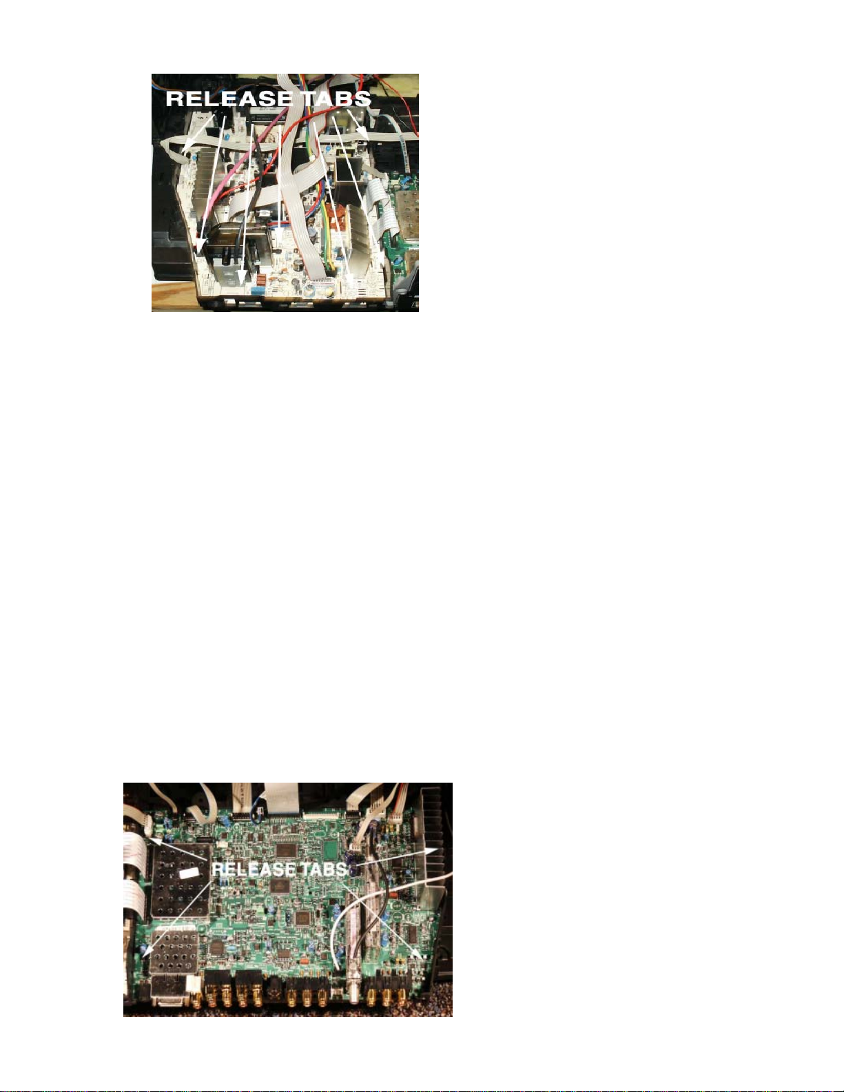
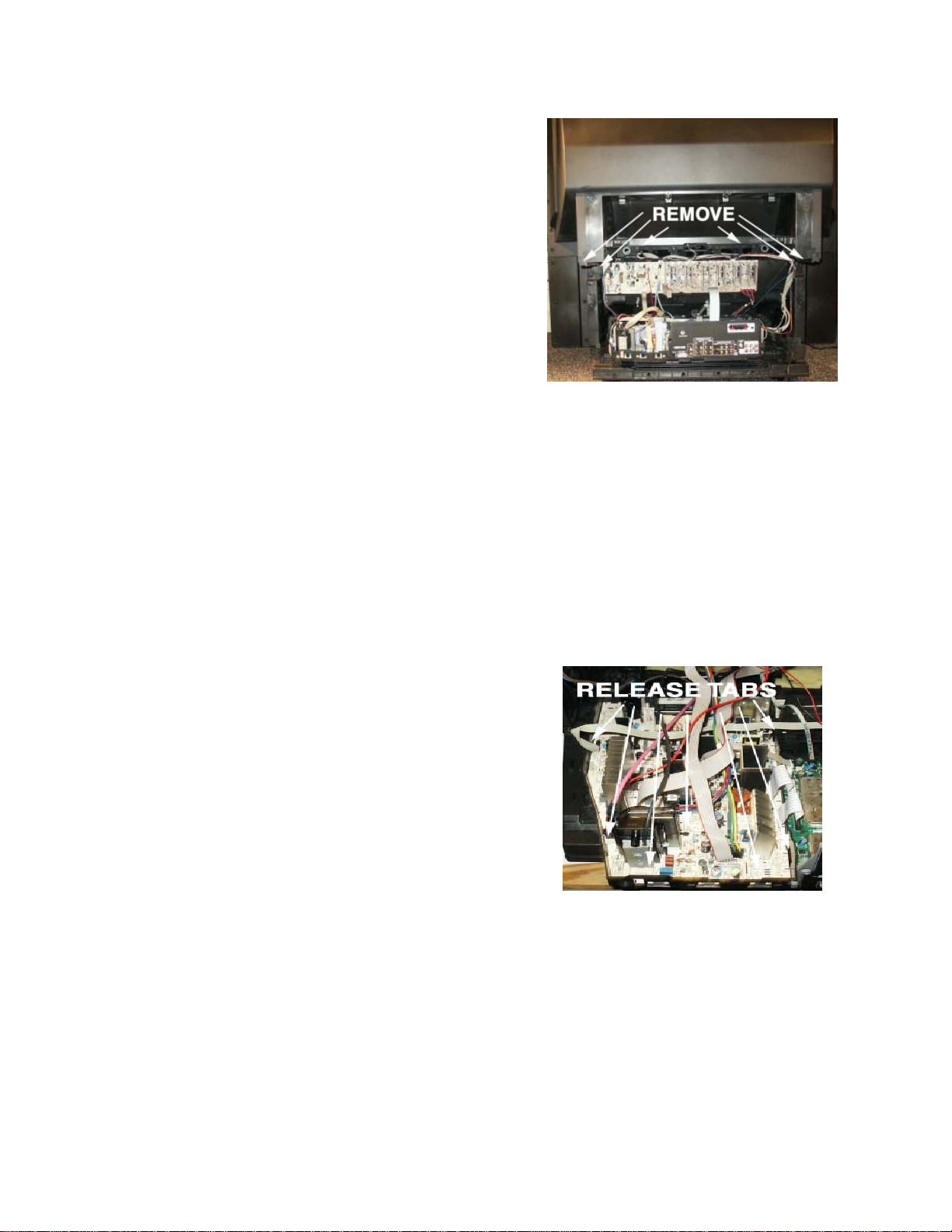
Power Supply/Scan PCB Removal
1. Remove Chassis Tray from bottom Cabinet
Assembly (See Chassis Tray Removal).
2. Remove Dynamic Focus PCB.
3. Disconnect cables
4. Press tabs to release Power Supply/Scan
PCB from the Chassis Tray.
5. Lift PCB from the rear to remove from
chassis tray .
Reinstall in reverse order .
II-1
Page 17
Mains Input Doubler (MID) PCB Removal
1. Remove chassis tray from cabinet assembly
(See Chassis Tray Removal).
2. With a small screwdriver release 2 tabs
holding MID bracket to chassis tray .
3. Disconnect cables.
4. Release tabs on chassis tray.
5. Lift MID PCB from the chassis tray.
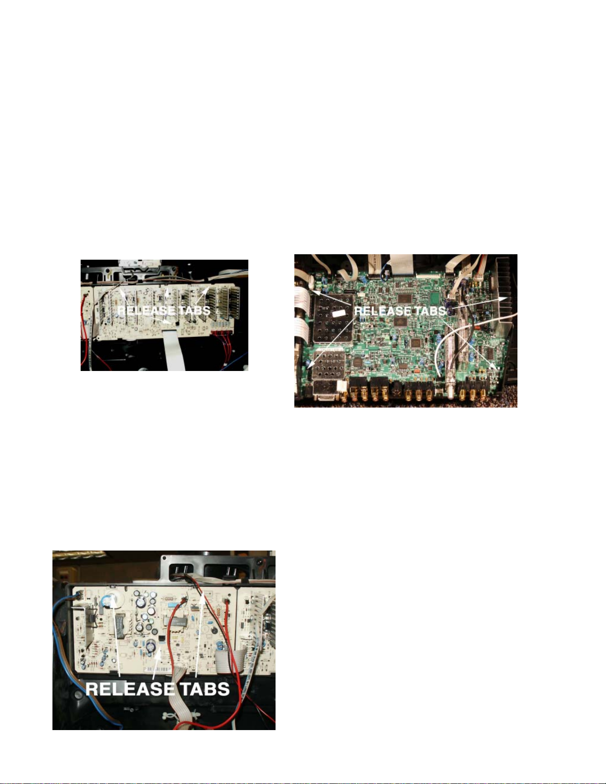
Small Signal (SSB) PCB Removal
1. Remove DRI PCB (See above).
2. Remove DRI PCB Bracket. Release 2 tabs
at front of bracket. Lift front of bracket to
remove from chassis tray.
3. Remove 3 T-10H Torx head screws from
Jack Panel portion of the Chassis Tray
Assembly.
4. Disconnect cables.
5. Release tabs on Chassis T ray Assembly.
6. Slide Small Signal PCB towards the front of
the instrument and lift out to remove.
7. Reinstall in reverse order .
II-2
Page 18
DISASSEMBLY
Projection Models
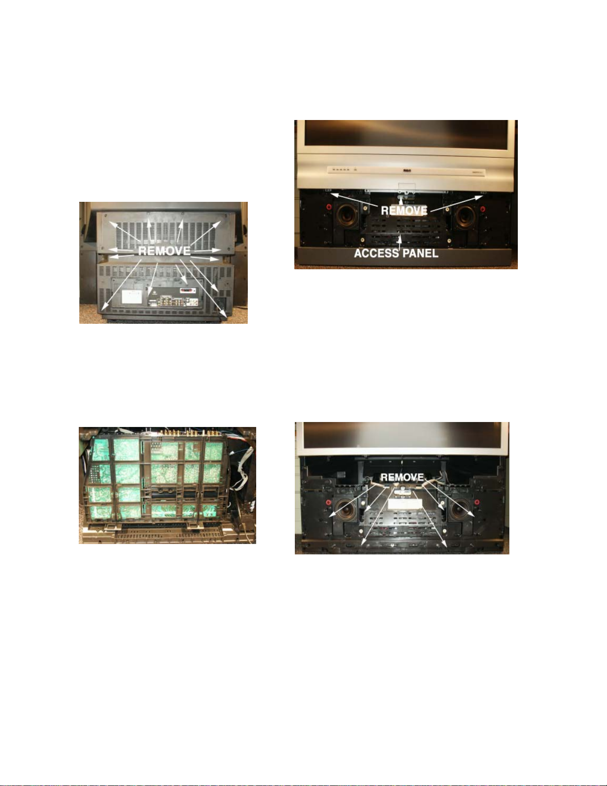
Back Cabinet Removal
The back cabinet is held in place with several T -20
Torx head screws. The number and placement of
the screws may vary with cabinet designs. If model
has a subwoofer, disconnect cable at bottom of
cabinet assembly .
Chassis Tray Removal/Service Position
1. Remove the Back Cabinet Assembly
2. Lift sides of chassis tray assembly
3. Slide chassis tray assembly away from
CRT’s approximately 2 - 3".
4. Chassis will release from bottom cabinet
assembly.
5. Chassis may now be placed in the Service
Position. See diagram below.
3. Remove T-20 Torx head screws holding
front cabinet assembly. Unplug cables for
Front Panel Assembly and Front Audio/
Video Jack Assembly. FPA and Front A/V
Assemblies may now be serviced.
4. Access Panel may now be removed to allow
service of Kine Drive circuits.
5. Remove T-20 Torx head screws securing
front frame to cabinet assembly .
6. Speaker Assemblies may now be serviced.
Remove 5 T-20 Torx head screws to gain
access to crossover circuit located internal
to each speaker enclosure.
7. Reassembly in reverse order. If instrument
is a DVD Model, ensure DVD door is aligned
properly
6. T o place chassis tray back into the cabinet,
align the bottom of the chassis tray with the
locking mechanism of the bottom cabinet
assembly.
Cabinet Front Disassembly , FPA/Front A/V
PCB/Speaker Removal
1. Grasp Speaker Grille on the sides. Pull
away from instrument to remove.
2. Remove T-20 Torx head screws holding
front bottom.
Screen/Mirror Removal, IR PCB/Convergence
Auto Sensor Replacement.
1. Remove Front Cabinet Assembly. (See
steps 1 and 3 in Cabinet Front Disassembly)
2. Remove T-20 Torx head screws securing
Screen Assembly to cabinet frame.
3. With Screen Assembly removed, IR PCB
may now be serviced.
4. Convergence Auto Sensors may now be
replaced. Remove T-20 Torx head screws
securing each sensor to the cabinet frame.
5. Remove 4 T -20 Torx head screws securing
the mirror to the cabinet frame.
II-3
Page 19
CRT Assembly Removal, Focus/Screen
Assembly/HV Splitter Assembly Replacement
1. Remove Cabinet Front Assembly. (See
Cabinet Front Disassembly).
2. Remove Screen Assembly. (See Screen/
Mirror Removal).
3. Remove Kine Drive PCB’s from CRT.
4. Remove IR PCB from holder located on top
of CRT Assembly.
5. Disconnect Convergence Y oke Cables from
Convergence Amp PCB and Deflection
Yoke Cables from Convergence Adapter
PCB. Disconnect SVM cables and CRT
ground cables from each Kine Drive PCB.
6. Remove Anode Lead from HV S plitter (Lead
from IHVT to HV Splitter). Anode Lead can
be removed by pushing in slightly , then twist
and pull. If HV Splitter Assembly needs to
be replaced, remove Anode Leads to each
CRT . Use same procedure to remove leads.
Disconnect Ground lead. Remove ¼ inch
screw securing assembly to bracket
7. Remove ¼ inch screw securing Focus/
Screen Assembly to CRT Frame.
8. Remove 4 T -20 Torx head screws securing
CRT assembly to Cabinet Frame. Slide CRT
Assembly out to remove from cabinet. (It
may be necessary to remove the Speaker
Assemblies).
9. Reinstall in reverse order .
7. Lift Upper Cabinet straight up to remove.
8. Reassemble in reverse order.
Power Supply/Scan PCB Removal
1. Remove Chassis Tray from bottom Cabinet
Assembly (See Chassis Tray Removal).
2. Disconnect cables
3. Press tabs to release Power Supply/Scan
PCB from the Chassis Tray.
4. Lift PCB from the rear to remove from
chassis tray .
5. Reinstall in reverse order .
Note: Lead Dress is critical to the operation of the
instrument. Care should be taken to dress
all leads in their original positions. See
section on Critical Lead Dress.
Upper Cabinet Assembly Removal
For ease of service the upper and lower cabinet
assemblies may be separated.
1. Remove back cabinet assembly . (See Back
Cabinet Removal).
2. Remove Cabinet Front Assembly. (See
Cabinet Front Disassembly .
3. Remove Front Panel Assembly and Front
A/V from holder. (Front A/V may be left in
the Cabinet Front Assembly by
disconnection the cables).
4. Disconnect cable to Auto Convergence
Sensors.
5. Disconnect cables from DVD assembly if
instrument is a DVD model.
6. Remove 4 T -20 Torx head screws securing
Upper and Lower Cabinet Assemblies.
Mains Input Doubler (MID) PCB Removal
1. Remove chassis tray from cabinet assembly
(See Chassis Tray Removal).
2. Remove bracket behind SSB board.
3. With a small screwdriver release 2 tabs
holding MID bracket to chassis tray .
II-4
Page 20
DISASSEMBLY
4. Disconnect cables.
5. Release tabs on chassis tray.
6. Lift MID PCB from the chassis tray.
Convergence Adapter PCB/ Convergence
Amplifier PCB Removal
1. Remove T -20 Torx head screw from middle
of PCB.
2. Release tabs at top of PCB to remove from
bracket.
3. Disconnect cables
4. Reinstall in reverse order .
Small Signal (SSB) PCB Removal
1. Remove DRI PCB (See above).
2. Remove DRI PCB Bracket. Release 2 tabs
at front of bracket. Lift front of bracket to
remove from chassis tray.
3. Remove 3 T-10H Torx head screws from
Jack Panel portion of the Chassis Tray
Assembly.
4. Disconnect cables.
5. Release tabs on Chassis T ray Assembly.
6. Slide Small Signal PCB towards the front of
the instrument and lift out to remove.
7. Reinstall in reverse order .
Convergence Signal PCB Removal
1. Using a screwdriver pry up on tab under
bracket. (See diagram below).
2. Pull back on bracket to remove convergence
signal bracket from chassis.
3. Release tabs on top of bracket to remove
Convergence Signal PCB.
4. Disconnect cables.
5. Reinstall in reverse order .
DVD Unit Removal (PTV Models)
1. Remove Back Cabinet Assembly.
2. Remove Front Cabinet Assembly (See Front
Cabinet Disassembly).
3. Disconnect cables from DVD Unit.
4. Remove T-20 Torx head screws securing
DVSD Unit to Cabinet Frame.
5. Lift to remove DVD Unit from Cabinet.
6. Reinstall in reverse order .
II-5
Page 21

III
Interconnect
Page 22
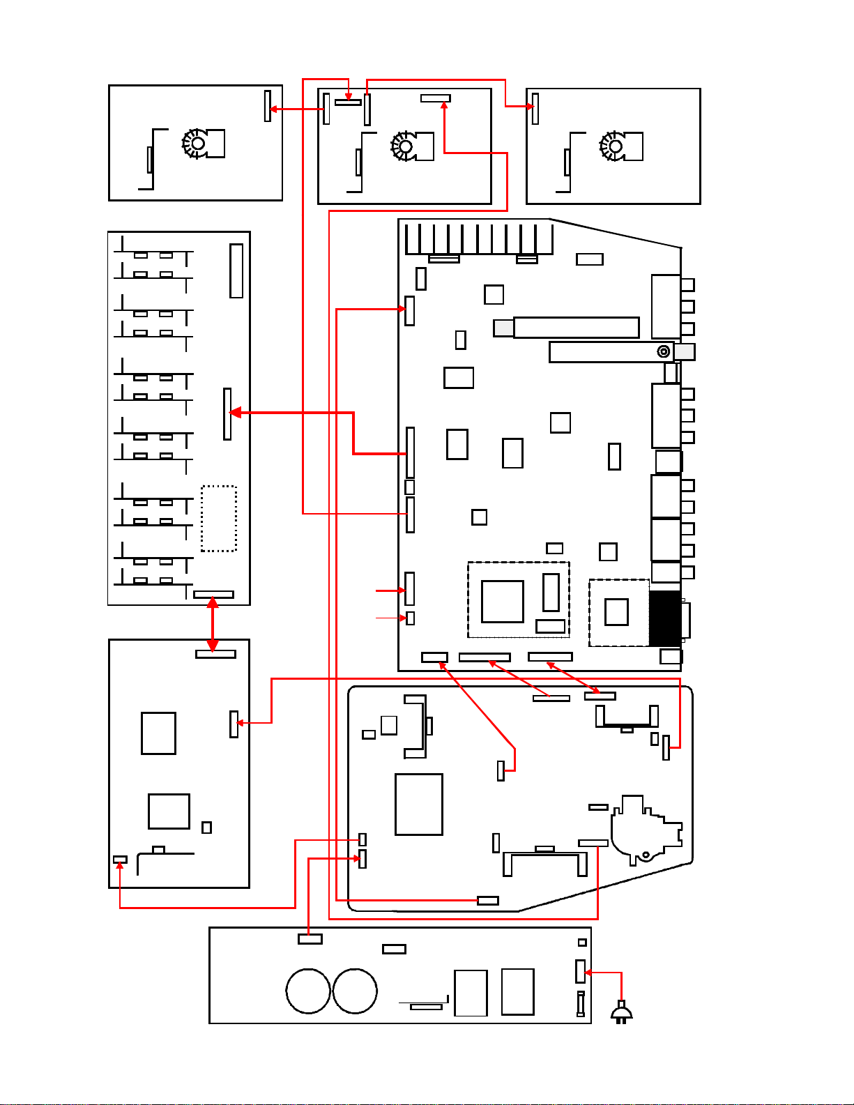
Interconnect
BB104
Red
IB101
BB204
BB203
BB201
IB201
BB202
Grn
G-CRT
R-CRT
BW001 BW002
BA001
IA001
BA010
BA002
CAM
IC040
SSB
BW005
GH GV RH RV
BV
Watchdog
Circuit Area
BH
BW004
IR & Key Board
IK201
BK270BV500
IV400
BR001
IR001
BB303
Blue
IB301
B-CRT
IA900
Out
n
o
c
e
S
r
e
n
u
T
d
r
e
n
u
T
IV100
IV300
IR006
Gem Cam
IX300
IX400
IT600
Monitor
n
i
a
M
E
T
s
C
B
s
I
u
1&2
CVBS
S
Vid
2
Comp
1
Comp
DVI
Aud
DVI
BK202
LP050
DP400
BP501
TP020
LP401
BL660
LP020
LP605
BL600
CPS
LP650
IP650
BP610
TP630
B
2
0
4
P
MID
CP410
IP080
PSD
BP010 BP011
BP401
CP411
BP500
BP005
BP150
BP120
BP130
LP400
TL010
BV001
BL111
BL035
BL200
BP414
BP400
FP400
G
Link
BL500
BF001
LL008
III-1
Page 23

III-2
Page 24

Page 25

IVII-4
VOLTAGE
CHARTS
Page 26
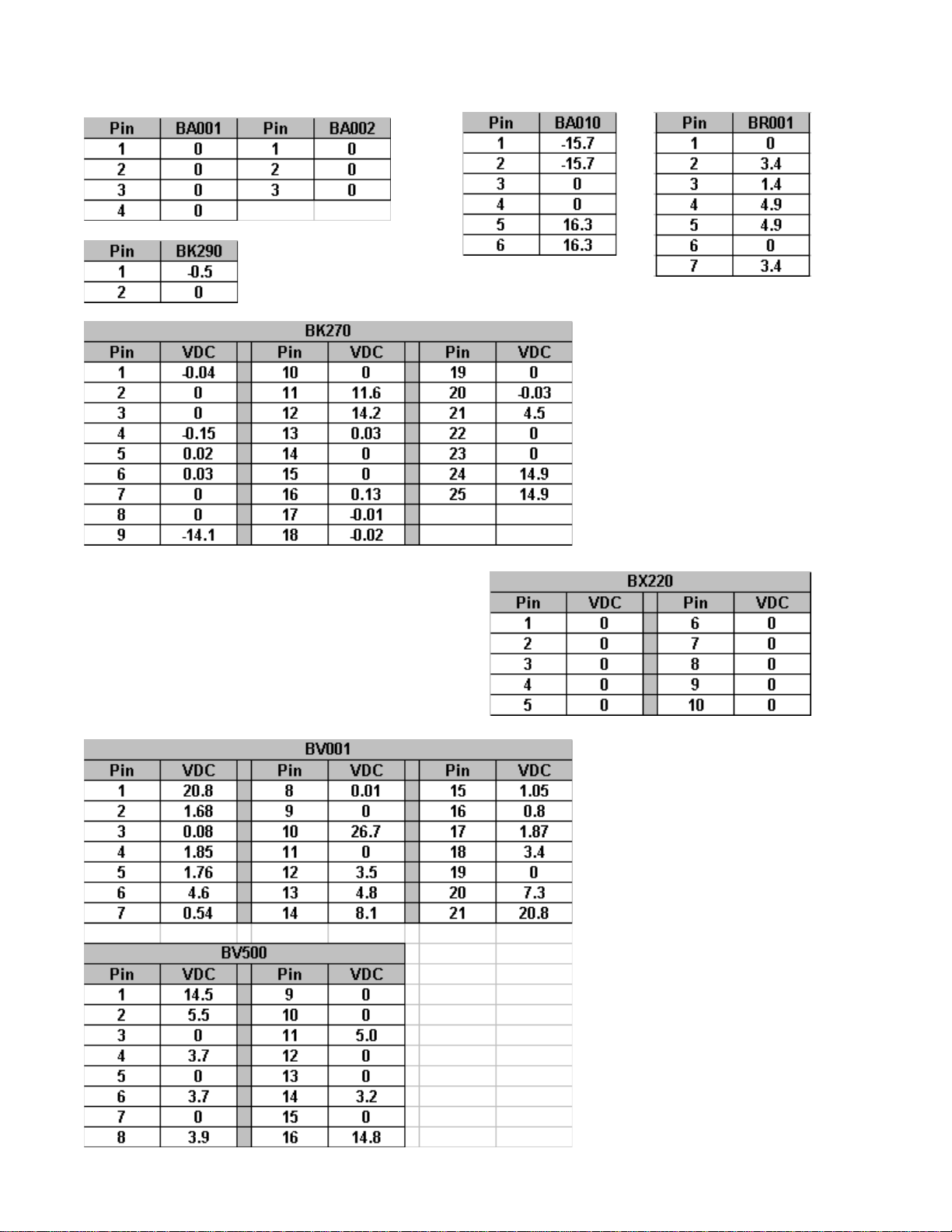
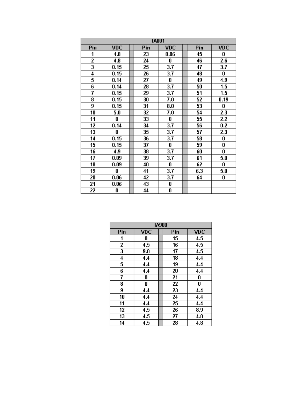
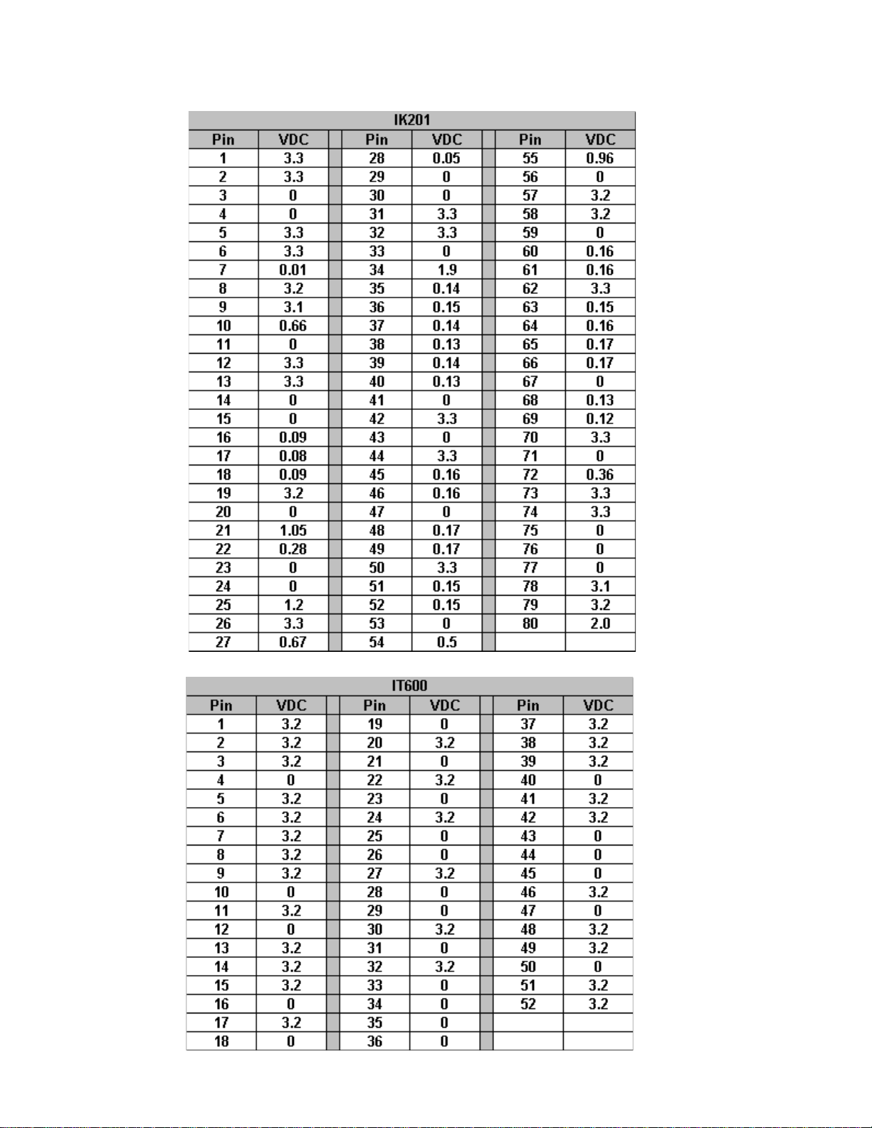
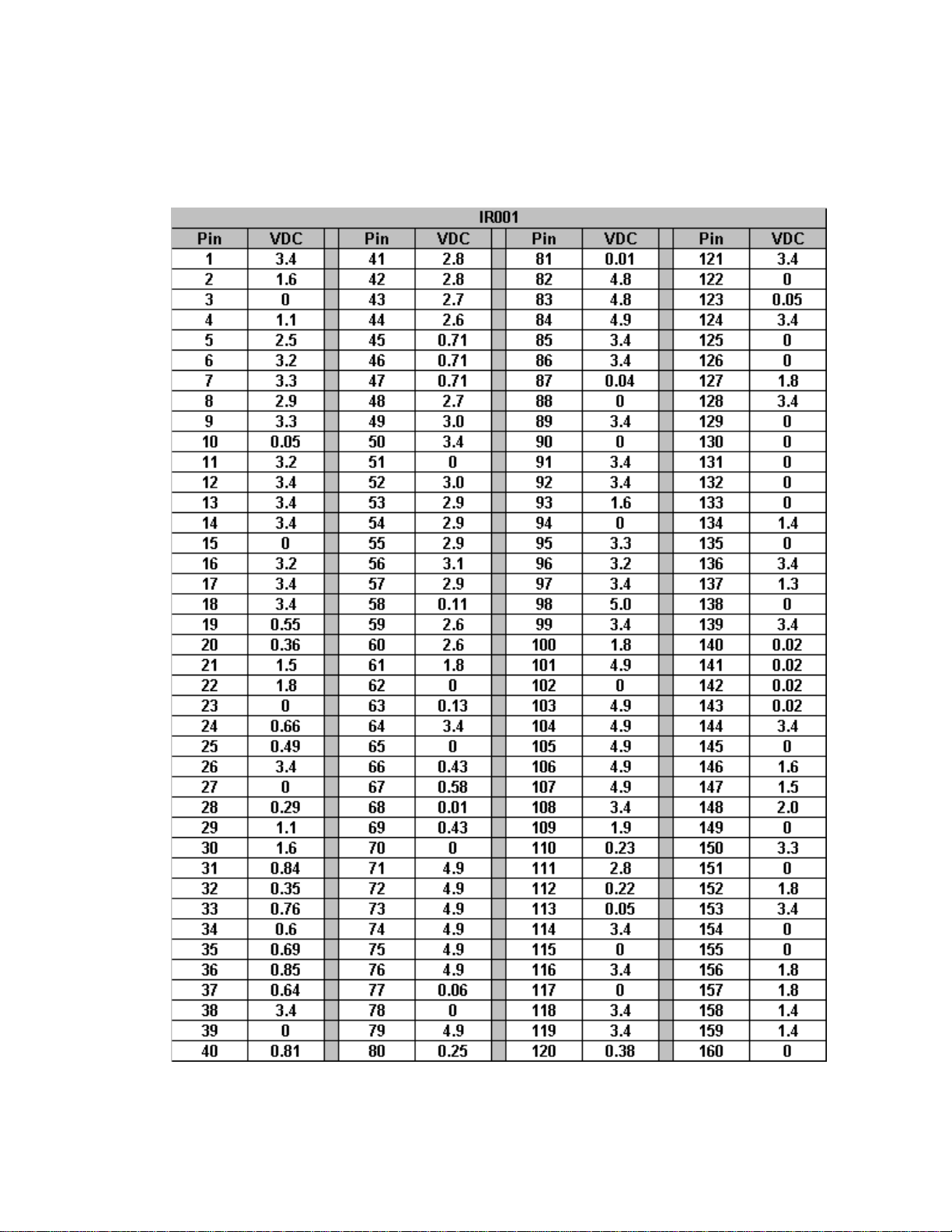
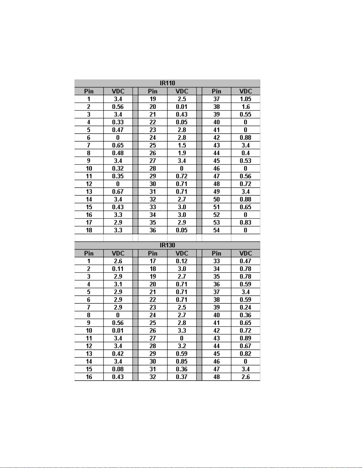
VOL T AGE CHARTS
IV-1
Page 27
VOL T AGE CHARTS
IV-2
Page 28
VOL T AGE CHARTS
IV-3
Page 29
VOL T AGE CHARTS
IV-4
Page 30
VOL T AGE CHARTS
IV-5
Page 31

VOL T AGE CHARTS
IV-6
Page 32

VOL T AGE CHARTS
IV-7
Page 33

V
WAVEFORMS
Page 34

WAVEFORMS
WFC10 WFC11
WFC12 WFC13
WFC14 WFC15
V-1
Page 35

W AVEFORMS
WFC16
WFC18 WFC19
WFC17
WFC20 WFC21
V-2
Page 36

WAVEFORMS
WFC22 WFC23
WFC24 WFC25
WFC26 WFC27
V-3
Page 37

W AVEFORMS
WFC28 WFC29
WFC30 WFC31
WFC32 WFC33
V-4
Page 38

WAVEFORMS
WFC34 WFC35
WFC36 WFC37
WFC38 WFC39
V-5
Page 39

W AVEFORMS
WFC40 WFC41
WFC42 WFC43
WFC44 WFC45
V-6
Page 40

WAVEFORMS
WFD01
WFD03
WFD02
WFD04
WFD05 WFD06
V-7
Page 41

W AVEFORMS
WFD07 WFD08
WFD09 WFD10
WFD11 WFD12
V-8
Page 42

WAVEFORMS
WFD13 WFD14
WFD15 WFD16
WFD17 WFD18
V-9
Page 43

W AVEFORMS
WFD19 WFD20
WFD21 WFD22
WFD23 WFD24
V-10
Page 44

WAVEFORMS
WFD25 WFD26
WFD27 WFD28
WFD29 WFD30
V-11
Page 45

W AVEFORMS
WFD31 WFD32
WFD33 WFD34
WFK01 WFK02
V-12
Page 46

WAVEFORMS
WFK04WFK03
V-13
WFK06WFK05
WFK08WFK07
Page 47

W AVEFORMS
WFP01WFK09
V-14
WFP02WFP01A
WFP03WFP02A
Page 48

WAVEFORMS
WFP03A WFP04
WFP04A WFP05
WFP05A WFP06
V-15
Page 49

W AVEFORMS
WFP07 WFP08
WFP09 WFP10
WFP11 WFP12
V-16
Page 50

WAVEFORMS
WFP13 WFP14
WFP15 WFP16
WFP17 WFP18
V-17
Page 51

W AVEFORMS
WFP19 WFP120
WFP21
WFP23 WFP25
WFP22
V-18
Page 52

WFP25
V-19
Page 53

VI
ALIGNMENT
PROCEDURES
Page 54

ALIGNMENT PROCEDURES
Operating Conditions
Unless otherwise noted, the following conditions
must be observed when aligning the ITC222 chassis:
Chassis must be operated from a 120V AC isolation
transformer, with line volt age set to 120V AC (±2.0V).
Picture controls (black level, contrast, etc.) must be
set to factory presets via the Picture Quality menu.
Procedures must be performed in the sequence
given. A 10X probe must be used for oscilloscope
and frequency measurements.
The audio output leads must not be shorted together
or to ground with the chassis on. All video signals
must have -40 IRE sync tips unless specified
otherwise. Chassis AC power must be removed for
10 seconds before disconnecting any cable.
A 3-minute warm-up is required for chassis or
module related alignments. A 15-minute warm-up
is required for Kine or Convergence related
alignments.
Required T est Equipment
- Dual-Trace Oscilloscope
- Digital Voltmeter
- Frequency Counter
- Audio Signal Generator
- NTSC Signal Generator (B&K 1249, or
equivalent)
- MTS Signal Generator (B&K 2009, or
equivalent)
- Sweep/Marker Generator (or Standard Signal
Generator)
- YPrPb Signal Generator (DVD player w/YPrPb)
- DC Power Supply (5.0V/0.25A) for TAG001
- Chipper Check® software
- Chipper Check® interface box and computer
- Personal Computer (IBM Compatible w/ CD
ROM and Sound Card)
NOTE: For optimum performance it is critical that
this instrument be properly aligned. For Auto
Convergence to work correctly it is HIGHLY
RCOMMENDED that the geometry alignments are first verified
Small Signal Board (SSB) Replacement
All alignment data is stored in EEPROMs located
on the Small Signal Board (SSB). If the SSB needs
to be replaced, it is HIGHLY RECOMMENDED the
EEPROM data be downloaded by using Chipper
Check. Once the SSB has been replaced, upload
the alignment data back into the instrument. Then
verify that the instrument is properly aligned.
1. Open Chipper Check. Select “Dead Set”
“ITC222”. Follow the On Screen Instructions to
establish a connection. Fill in the Customer Information on the “Customer Info” tab and
change to the EEPROM tab.
The following menu should appear.
2. Press the “Replace SSB Board” The following
screen appears
VI-1
Page 55

The instrument should display the following menu:
Soft-Ver. ITC222_V100-0 000046 :37
DVD Soft -Ver. 3.12
Config. W - - V - - -P - Serial-No. AMN456789
QUIT
TUBE
CHASSIS SETUP
FEATURE SETUP
GEOMETRY
VIDEO
EVENT HISTORY
SOUND
MISCELLANEOUS
CONVERGENCE
DVD
3. Follow the instructions on this screen to copy
the alignment data from the defective SSB to
the new SSB.
NOTE: It may be necessary to perform the geom-
etry alignment to get the auto convergence
to work correctly . Please refer to the section
on Geometry Alignments
CRT Replacement (PTV Models)
If only 1 or 2 CRT’s are replaced use a convergence
pattern to align the new CRT. Align the new CR T to
the pattern generated by the existing CRT. Then run
Auto Convergence.
If all 3 CRT’s are replaced, it will be necessary to
first center the Green CRT using a pattern with a
center dot. Then align Red and Blue following the
Geometry Alignment procedures in the service data.
Service Mode
Most of the alignments for this chassis are softwaredriven. Most of the alignments must be accessed
and modified through the front panel service mode.
Entering the TV Service Mode Using the Front
Panel Controls
1. Press and release the POWER button to turn
the instrument off.
2. Wait 10 seconds before trying to enter the Field
Service Mode.
3. Press and hold the VOLUME DOWN and
CHANNEL DOWN buttons for at least 8
seconds.
4. The instrument will switch on and come up with
the field service main menu on the screen. LED
will illuminate before the picture comes up.
UP DOWN
SELECT
Main Menu
The CH /\ and CH \/ buttons on the front panel
are used to navigate up or down in the menu.
The VOL + and VOL - buttons on the FPA are
used to select a menu item or decrease or
increase a value in a selection list.
NOTE: Before the Field Service Mode is exited; you
must check STORE or all changes to
alignments will be lost.
The remote control can also be used to navigate
the field service mode.
• Clear button: When this button is pressed
the Field Service Mode disappears and the
every-day TV functions are available.
• Menu button: To re-enter the Field Service
Mode, make a long press on the Menu
button. The service technician re-enters in
the same menu point where he left the Field
Service Mode.
∧∧
•
∧: This button is used to navigate up in the
∧∧
menu.
∨∨
•
∨: This button is used to navigate down in
∨∨
the menu.
VI-2
Page 56

• <: This button is used to select a menu item,
to decrease a value or to select the previous
value in a selection list.
• >: This button is used to select a menu item,
to increase a value or to select the next value
in a selection list.
• OK: This button is used to select or deselect
a menu item.
Main Menu
Soft-Ver: Displays the current software version.
Runtime Counter: Displays the total runtime in
hours and mintues.
TUBE
Return
Tube Type RP 16x9
Store
Restore
UP DOWN SELECT
DVD Soft-Ver: For DVD models only , displays
the current software version.
Config: Displays the configuration code of the
instrument. Each character represents a
paraticular hardware feature or option.
Serial-No.: Displays the serial number of the
instrument.
Common features found in the submenus
Return: The submenu is closed and the main
Field Service Mode menu appears.
Defaults: The default values for the current
menu are copied from ROM to RAM.
Note: If Default is checked a complete realignment of
that particular menu is required.
Store: All current values from a menu group are
stored into memory .
Restore: The last stored settings for the menu
displayed are copied from NVM to RAM.
Tube Submenu
Chassis Setup
Subwoofer: Allows the instrument to be
configured for a subwoofer
Pict. Rotation: Specifies whether the picture
rotation option is available or not. (DV Models
Only)
Autoconvergence: Specifies whether the
autoconvergence option is available or not. (PTV
Models Only)
DVI: Specifies whether the DVI option is
available or not.
Toplight: Specifies whether the toplight option
is available or not.
CHASSIS SETUP
Re tur n
Tube Type Menu
1. Select the correct tube type from a pulled down
list on the right hand side of the menu. (This
will activate new tube type values along with
default video and geometry parameters)
2. Check STORE to save new parameters in
memory.
Subwoofer
Pict. Rota t ion
Autoconvergence
DVI
Toplight
Defaults
UP DOWN SELECT
Chassis Setup Submenu
VI-3
Page 57

Feature Setup
Curtains Effect: Determines if the curtains
feature is available to the user.
Opt. Still Pict. : Determines if the Optimised
Still Picture feature is available to the user.
Auto Film Mode: Determines if the Automatic
Film Mode Detection feature is available to the
user.
Burn-In Prot. : Determines if the Burn-In
Protection feature is available to the user.
FEATURE SETUP
Return
Curt ai n s Effe ct
Opt. Still Pict.
Auto Film Mode
Demo Mode
Burn-In Prot.
Welcome/Contact
Program Info
Defaults
UP DOWN SELECT
Feature Setup Submenu
Geometry Alignment
Entering the Geometry menu the display mode
must be set to Standard Scanning Mode (480i/
480p and 1080i). All 480i/480p alignment s should
be completed using the RF input. Use either
component input or DVI-input for 1080i
adjustments.
Geometry Submenu
Alignment Procedure (Direct View Models
Only)
NOTE: Unless otherwise noted all Geometry
adjustments must performed in both 480i/p
and 1080i modes.
1. Place the instrument in the Field Service Mode.
2. Enter the Tube submenu. V erify the correct tube
type is selected.
3. Enter the Geometry submenu.
4. Adjust H-Amplitude (Horizontal Amplitude) for
slight underscan.
5. Enter the Video submenu. Selct the G2 alignment. Adjust the Screen control on the flyback
until the just becomes visible.
VI-4
Geometry Submenu
Page 58

6. Adjust PL557 on the Dynamic Focus Board to
center the raster between the tube border.
7. Realign G2 for 150V on the highest cathode.
8. Tune the instrument to receive a crosshatch
pattern.
9. Return to the Geometry submenu.
10. Adjust V-Slope (Vertical Slope) until the middle
line of the test pattern is just visible.
1 1. Using a Monoscope pattern, adjust V -Amplitude
(Vertical Amplitude) until the first and last horizontal line of the test pattern is just hidden by
the tube.
NOTE: Instruments with 16/9 CR T’s must have this
alignment performed with the format set to
16/9.
12. Adjust V-Position (V ertical Position) until the picture is centered vertically. It may be necessary
to recheck the V-Amplitude (S tep 1 1) adjustment.
13. Adjust V-Linearity (Vertical Linearity) for equal
height of the squares in the crosshatch pattern.
NOTE: Instruments with 16/9 CR T’s must have this
alignment performed with the format set to
16/9.
14. Adjust H-Position (Horizontal Position) until the
test pattern is horizontally centered.
15. Using a Monoscope pattern adjust H-Amplitude
(Horizontal Amplitude) until the first and last horizontal line of the test pattern is just hidden by
the tube. It may be necessary to recheck the HPosition (Step 14) adjustment.
16. Using a Crosshatch pattern adjust EW-Amplitude (East West Amplitude) until the vertical lines
in the middle of the CRT are straight.
17. Adjust EW-Upper Corner (East West Corner)
until the vertical lines are straight at the top of
the screen.
18. Adjust EW-Lower Corner (East West Corner)
until are straight at the bottom of the screen.
19. Adjust EW-Symmetry (East West Symmetry or
H-Bow) until the left and right border of the screen
are the same.
NOTE: It may be necessary to repeat S teps 14- 19
after this adjustment for optimum
performance.
zontal amplitude will change with different beam
current at the same ratio as vertical amplitude.
23. H-Max and H-M set the range limitations of the
H-Amplitude adjustment. This adjustment should
only be used in cases where CRT is replaced
and it does not appear in the CRT list. To access
this adjustment, the Development Support must
be checked in the Miscellanous Setup menu.
24. Check the box to set the shutdown threshold for
the XRP circuitry . During this automatic process
the screen will blank, then reappear once it is
finished.
25. Before exiting the Geometry menu, check Store
to save changes to memory .
26. After the Geometry Alignments, check the EarthField Compensation (EFC) adjustment (DV Models Only). Enter the Advanced Picture Setting
Menu. Using a crosshatch pattern, adjust the
EFC for minimum picture rotation at the top and
bottom.
Alignment Procedure (Projection Models Only)
NOTE: Unless otherwise noted all Geometry
adjustments must performed in both 480i/p
and 1080i modes.
1. Place the instrument in the Field Service Mode.
NOTE: It is recommended the Geometry alignments
be performed using the Green CRT only.
2. Enter the Tube submenu. V erify the correct tube
type is selected.
3. Tune the instrument to receive a crosshatch
pattern.
4. Return to the Geometry submenu.
5. Adjust V-Slope (Vertical Slope) until the middle
line of the test pattern is just visible.
6. Exit the Geometry submenu and turn the instrument OFF. Disconnect the Convergence Yoke
connectors BW001 and BW002 (Located in
lower right corner of the Convergence Amplifier
PCB). Turn the instrument ON and tune to receive a center line pattern. Adjust horizontal and
vertical center lines according to the chart below with the static convergence magnets. When
completed turn the instrument OFF and reconnect the convergence yoke connectors.
20. Adjust H-Parallel (Horizontal Parallelogram) the
offset between the top and bottom of the picture.
21. Adjust EW-Trapezium (East West Trapezium)
for best compromise between Left and right vertical lines.
22. Adjust Breathing (EHT Compensation) until hori-
VI-5
Page 59

eziSneercS
"04)ni49.0(mc4.2)ni49.0(mc4.2
eniLretneCdeR
retneCfotfeLteS
Yoke Centering Ring Adjustment
eniLretneCeulB
If Chipper Check is not available it is possible to re-
retneCfothgiRteS
place a single CRT and realign geometry by using
the centering rings on the CRT.
"25)ni22.1(mc1.3)ni22.1(mc1.3
"65)ni92.1(mc3.3)ni
"16)ni73.1(mc5.3)ni73.1(mc5.3
92.1(mc3.3
7. Turn the instrument ON and place in the Field
Service Mode. Tune to recieve a crosshatch
pattern. Enter the Geometry submenu. Using a
Monoscope pattern, adjust V -Amplitude (Vertical Amplitude) until the first and last horizontal
line of the test pattern is just hidden by the tube.
8. Adjust V-Position (V ertical Position) until the picture is centered vertically .
9. Adjust V-Linearity (Vertical Linearity) for equal
height of the squares in the crosshatch pattern.
10. Adjust H-Position (Horizontal Position) until the
test pattern is horizontally centered.
1 1. Using a Monoscope pattern adjust H-Amplitude
(Horizontal Amplitude) until the first and last horizontal line of the test pattern is just hidden by
the tube.
12. Using a Crosshatch pattern adjust EW-Amplitude (East West Amplitude) until the vertical
lines in the middle of the CRT are straight.
13. Adjust EW-Trapezium (East West Trapezium)
for best compromise between Left and right
vertical lines.
14. Adjust EW-Symmetry (East West Symmetry or
H-Bow) until the left and right border of the
screen are the same.
NOTE: It may be necessary to repeat Steps 10-
14 after this adjustment for optimum
performance.
15. Adjust Breathing (EHT Compensation) until horizontal amplitude will change with different beam
current at the same ratio as vertical amplitude.
16. H-Max and H-M set the range limitations of the
H-Amplitude adjustment. This adjustment
should only be used in cases where CRT is replaced and it does not appear in the CRT list.
To access this adjustment, the Development
Support must be checked in the Miscellanous
Setup
Using the convergence pattern available when in service menu the pattern from the replacement CRT
may be adjusted to align with either of the two remaining CRT's using the centering rings shown in
Figure 1.
Phosphor
Screen
Centering
SVM Y oke
Kine
Socket
Figure 1 - Centering Rings
First make certain the replacement CRT and yoke
are assembled and placed back in the mounting as
close as possible to the original CRT and yoke. At
this point having the convergence pattern on screen
will assist in the mechanical mounting.
Using the centering rings and observing the convergence pattern, rotate and move the pattern until the
replacement color overlays as close as possible to
the two colors not replaced. Moving the ring tabs
together around the neck of the CRT draws the raster in small circles. Spreading the tabs ap art moves
the raster in more linear angles. The closer the tabs
are together, the less affect on the CRT beam they
have.
When the raster is as close as possible fix the magnets with paint or nail polish to prevent further movement.
VI-6
Page 60

After fixing the magnets, if gross geometry errors
are apparent, geometry alignment is indicated. If
the raster is close, use the "Auto-convergence" feature provided in the consumer menu to re-align convergence. This should correct most minor geometry problems. Follow auto-convergence with the
consumer red and blue centering adjustments, then
evaluate the raster again.
In most cases convergence will now be acceptable.
If only slight convergence errors are noted the technician should enter the manual digital convergence
menu and begin "touch-up" of the screen.
If gross geometry errors are still apparent re-evaluate whether the errors are noticable on the replacement CRT or whether they are global, affecting all
three CRT's. If the errors affect all three CRT's a full
geometry alignment is indicated. If the errors only
affect one CRT, particulary the replacement, return
to the mechanical placement and centering ring adjustments and begin those procedures again.
Rotate Tabs Together
Focus Adjustments
Before attempting the Focus Adjustments, allow
the
instrument to warm up for a minimum of 15
minutes.
Dynamic Focus CRT (DV Models Only)
1. Tune the instrument to receive a crosshatch
pattern.
2. Turn the F1 (Static) control on the focus block
fully clockwise
3. Adjust the F1 control while observing the vertical lines along the left side of the screen for best
possible focus.
4. Turn the F2 (Dynamic) control on the focus block
fully clockwise.
5. Adjust the F2 control while observing the
horzontal lines. Adjust for best possible focus.
6. Repeat step 3 and 5 for best possible overall
focus.
Single Focus CRT (DV Models Only)
1. Tune the instrument to receive a crosshatch
pattern.
2. Turn PL501 (Located on the Dynamic Focus
PCB) to the full counter clockwise position.
3. Adjust F2 on the focus block for best possible
focus of the horizontal lines.
4. Adjust PL501 for best possible focus of the vertical lines.
5. Repeat steps 3 and 4 for best possible overall
focus.
Spread Tabs Apart
Figure 2 - Centering Ring Tab Movement
Focus Adjustment (PTV Models)
1. Tune instrument to receive a crosshatch pattern.
2. Preset Contrast to maximun.
3. Adjust each CRT separately. Cover the two
CRT’s not being adjusted and adjust for best
overall focus.
5. Adjust the Green Electrical Focus control, located
behind the speaker grill for best overall focus.
6. Repeat procedure for the Red and Blue CRT’s.
VI-7
Page 61

Video Alignments
VIDEO PAL RF - BG
Return
Peak White
Whitepoint R
Whitepoint G
Whitepoint B
G2 Alignm ent
Scaling Colour
Scaling Brightness
Cuto ff R
Cuto ff G
UP DOWN SELECT/CHAN GE
VIDEO PAL RF - BG
Scaling Contrast
Scaling Tint
Contrast max
Drive Loop Dis able
Text Contrast
Full W hite 4/3
Driv e L evel
Defaults
Store
Restore
UP DOWN SELECT/CHANGE
Video Alignment Submenu
D4
80
F0
40
- 22
78
+90
D4
80
-18
- 22
78
12. Select a 75% color bar test pattern.
13. Connect a scope to the Blue Cathode of the
CRT board.
14. Adjust the Scaling Color to the levels shown
below.
Note: This alignment must be performed in each
of the following modes, Tuner, Comp 1H,
Comp 2H, DVI and AUX_RGB (if DVD
option is installed).
16. The Drive Level Alignment is preset
according to the CRT type selected and
does not need to be adjusted.
17. Before exiting the Video Alignment
Submenu, check Store to save all
alignments.
Before attempting the Video Alignment s, allow the
instrument to warm up for a minimum of 15 minutes.
1. Tune the instrument to receive a
crosshatch pattern.
5. Place the instrument in the Field Service
Mode.
6. Enter the Video submenu.
7. Select G2 adjustment.
8. Adjust Screen control until retrace lines
become visible, then adjust to make retrace
lines invisible.
9. Press any key to exit the G2 alignment
mode.
10. Select a pluge test pattern. Pattern should
have a 0% background with a -2% and
+2% bar.
11. Adjust Scaling Black Level to make the 2% bar invisible, keeping the +2% bar
visible.
Color T emperature
Color Temperature for the ITC222 is similar to past
chassis. Some form of staircase pattern similar to
the following figure is required. Proper identification
of the “0” (if available) and “7.5” or “setup” bars on
screen and the waveform produced on the cathodes
of the CRT will be needed. Consult the specifications
manual for the pattern generator used to confirm
the location of these bars.
The oscilloscope waveform shows the relationship
between the bars and the video signal at the
cathodes of the CRT. This waveform is present on
all three cathodes. With the oscilloscope adjusted
to provide a full peak to peak readout of the
waveform at the horizontal rate, the 7.5 IRE setup
bar will the critical area. Be certain this bar can be
identified using the equipment available. If a 7.5 IRE
bar is not available, 10 IRE may be used.
VI-8
Page 62

It should be noted that bar patterns differ . Some vary
from 10 to 100 IRE in various steps and in different
directions, but most should have an identifiable 7.5
to 10 IRE bar.
The purpose of the color temperature setup is to
assure uniform gray level from black to the brightest
scenes. If a uniform gray screen is displayed, no
matter the brightness level, no tinting in either red,
green or blue direction should be apparent. This is
known as “color tracking”. Once the proper color
temperature is set, AKB will maintain the cutoff of
the CRT to assure proper low light performance.
Black Cutoff R/G, Whitepoint R/G/B Setup
(Recommended Method)
1. Apply a gray test pattern giving a 12 IRE
flat window. Connect Colorimeter near the
center of the screen.
2. Adjust Black Offset R and Black Offset G to
obtain the following color coordinates:
Direct View Projection TV
X 0.282 0.283
Y 0.298 0.296
3. Apply a gray test pattern giving a 50 IRE flat
window.
4. Adjust Whitepoint R, G, and B for the
following color coordinates:
Direct View Projection TV
X 0.282 0.278
Y 0.298 0.291
Note: This alignment must be done in the following
modes, RF (NTSC), Comp 1H, Comp 2H,
DVI and AUX_RGB (If unit has DVD option
installed).
Black Cutoff R/G, Whitepoint R/G/B Setup
(Alternative Method)
1. Apply a vertical gray bar staircase pattern
(at least 8 bars from “7.5” to “>75” IRE).
Identify the 7.5 IRE bar location. It is the
“black” or “cutoff” bar . For these adjustments
this bar and the next brighter bar will be
used. On most patterns the remainder of
the bars will progressively become brighter.
2. Adjust Black Cutoff R or Black Cutoff G until
any tinting disappears from the black bar.
When properly adjusted the adjacent bar
should be a very low level gray with no color
tinting.
3. Now observe the brighter portions of the
bars. Adjust Whitpoint R, G, or B to remove
any signs of tint in the higher brightness
bars. Observe the bars for signs of CRT
overdrive. Some compromise may be
required, but the higher IRE bars should be
as free from color tinting as possible.
Note: There are separate color temperature
alignments for RF (NTSC), Comp 1H, Comp
2H, DVI and AUX_RGB (If unit has DVD
option installed).
Peak White Alignment
1. Apply a white centered pattern of 100 IRE
2% of the picture surface on a dark
background.
2. Adjust for peak white at center of the screen.
3. Check Scaling Black Level, Whitepoint,
Black Offset and Peak White adjustments.
It may be necessary to adjust these
alignments several times for optimum
performance.
VI-9
Page 63

Note: This alignment must be done in the following
modes, RF (NTSC), Comp 1H, Comp 2H,
DVI and AUX_RGB (If unit has DVD option
installed).
Full White 3/4 Alignment
1. Insert a full white pattern of 100 IRE through
RF. (Instrument will automatically set to ¾
mode).
2. Adjust for full white across the screen.
T ext Contrast, Contrast Max, Scaling Contrast
Alignments
1. Insert a white centered pattern of 100 IRE,
2% of the picture surface with a black
background.
2. Adjust for peak white.
3. Contrast Max and Scaling Contrast are
preset according to the CRT type selected
and do not need to be adjusted.
Event
If a run-time event occurs, its error code will be stored
in the NVM. The stored event codes can be read in
one of two methods. The first is with the event menu.
The last five event codes will be displayed, along
with a time stamp from the run time counter. The
time stamp will display the last occurrence of a particular event. The time stamp is displayed as “Run
Hours”. An event counter counts how many times
that event has occurred. The counter will not count
beyond 255. The most recent event code is displayed
on top. To clear the event codes from memory, select the Clear Event Codes box. A long press will
clear all stored codes.
Only the last error code stored in the NVM can be
read with this method. The LED will blink two
separate digits.
Example, if the error code of 23 is the last error code
stored
in the NVM, the LED will have 2 short flashes,
followed by a short pause. Then will flash 3 times,
followed by a long pause. This will be repeated 4
times.
First allow the instrument to sit unplugged for 60
seconds. At plug in the LED will first blink twice to
indicate microprocessor has reset. When an attempt
is made to power up, the instrument will attempt 3
times to start. The LED will display a series of flashes
followed by the error codes. The LED will flash the
error code 4 times.
Sound Setup
Effect Strength (MED): Modifies the bass effect
strength for the user setting MEDIUM.
Effect Stength (HIGH) : Modifies the bass effect
strength for the user setting HIGH.
Low Pass Frequency: Modifies the low pass
cut-off frequency.
High Pass Frequency : Modifies the high pass
cut-off frequency.
Sub-woofer Corner Frequency : Modifies the
sub-woofer corner cut-off frequency.
SOUND
Return
Effect Strengt h (MED) 80
Effect Strengt h (HIGH) 9A
Low Pass Frequency 80
High Pass Frequency 56
Sub-wo ofer Corner F r eq u ency 80
Defaults
Store
Rest ore
UP DOWN SELECT/CHANGE
EVENT HISTORY
Return
Clear Event Codes
Code Co unt T ime Stamp
11 00 1 00 0135:30
24 01 2 00 0090:10
78 00 3 00 0043:54
51 00 1 00 0001:20
00 00 0 00 0000:00
Test: Brightness Sensor: 2 Colour: R
Direction: Right Value: 125 Scan mode: 2H
UP DO WN SELECT/CHANGE
Event Submenu
Sound Setup Submenu
VI-10
Page 64

Miscellaneous
A
Clear Programs: Select with a 2 second press
to clear all programs stored in memory and set
Picture Preference, User Picture and Audio
settings to factory values. Returns the
instrument to “Out of Factory Mode”.
Default Presets : Sets the default value for all
factory sound and picture presets.
Bus Quiet: In this mode the NVM can be read,
modified or reprogrammed. Enter this function
with with a 2 second press. This mode is
cancelled with a press of Clear, Lef t, Right, Up,
Down or On-Off keys.
Level 3: Provides 195 adjustment points
CONVERGE NC E AL I G NM E N T
Ret u r n
1 (3 x 3 )
2 (5 x 5 )
3 ( 1 5 x
1 3 )
Le vel
Le vel
L e v e l
S e n s or c a l i br a t i o n
u t o c o n v er ge nc e
Def a ul t s
St or e
R e s t or e
10 80
Development Support : Enables or Disables
access to development support functions in
the field service menus.
Restore Factory Settings : Restores the
correct “Out of Box” condition.
Switch 2nd T uner to Main : Causes the current
signal on the 2nd tuenr to be switched to the
main screen and the monitor output jacks. Any
channel change will override this feature and
return tuning to normal.
MISCELLANOUS
Return
Clear Progs
Default Presets
Bus Quiet
Development S uppo rt
Restore Factory Settings
FFI Bit
Switch 2nd tuner to main
UP DOWN SELECT
Miscellaneous Setup Menu
Convergence (PTV Models Only)
U P
D O W N
S E L E C T / C H
A N G E
Convergence Submenu
It is recommended to adjust Levels 1 and 2 only if
repairs have been made to the Convergence Signal
circuitry or after CRT replacement. Before
performing the Convergence Alignment procedure
it is HIGHLY RECOMMENDED the Geometry
Alignment of the instrument is checked.
Note: Alignments must be performed in order. If
Level 3 is adjusted, prior to Levels 1 or 2,
all Level 3 alignments will be lost.
In Level 1 and 2, Press OK to select the color to be
aligned. The position of the adjustment point can
adjusted using the navigation keys (up, down, left
and right) on the remote. Press the 2 key of the
remote to move to the next adjustment point. Press
the EXIT/CLEAR key to exit when completed.
Level 3 alignment works simular to Levels 1 and 2.
The only difference, to move to the next adjustment
point press 2 (up), 8 (down), 6 (right) and 4 (left) on
the remote unit. When completed with convergence,
press STORE to save all changes.
The ITC222 employs a ditigal convergence circuit
that makes it possible to electronically align up to
208 separate points on the screen. 3 levels of
convergence adjustment is provided.
Sensor Calibration is used to calculate a reference
border for the autoconvergence photo sensors.
Check the box to begin the process.
Autoconvergence starts the autoconvergence
process.
Level 1: Provides 9 adjustment points
Level 2: Provides 25 adjustment points
Defaults enters a default submenu. Checking the
box loads a set of default values from the
VI-11
Page 65

convergence backup NVM to the Convergence IC
RAM. The box will remain checked until the value is
changed or store or restore is pressed in the
convergence submenu.
Note: Before the Convergence Alignement menu
is exited, you must check Store or all
settings will be lost.
Manual Convergence Procedure
1. Turn instrument “On”. Allow to warm up for
20 munitues. Turn instrument “Off”. Enter
the Service Menu holding the “Channel
Down” and “Volume Down” on the FPA
for 8 seconds. Enter the “Convergence
Menu”.
2. Perform “Level 3” (and/or Level 1, Level
2) manual convergence as describe above.
When completed, press “Clear”, then
select “Return” to go back to the main
Convergence Alignment Menu.
3. Check “Store” in the main Convergence
Menu. A check mark will appear in the box.
4. Select “Defaults” to enter the Default
Menu.
5. Select “Store Defaults”. Press and hold
OK on the Remote for 2.5 seconds. Then
select “Return” to go back to the main
Convergence Alignment Menu.
6. Perform “Sensor Calibration”. Select it
and press “OK”.
DVD (DVD Models Only)
1. Place the instrument in the Field Service Mode.
2. Enter the DVD submenu.
3. Activate DVD Factory Mode by selecting the box.
Press and hold the OK button for at least 2 seconds. The screen will then show the menu shown
below. This process may take several seconds.
1. Place the instrument in the Field Service Mode.
2. Enter the DVD submenu.
3. Activate DVD Factory Mode by selecting the box.
Press and hold the OK button on the remote for
at least 2 seconds. The menu will then change
to the menu shown below. This process may take
several seconds.
DVD
Return
Activate DVD Factor y Mode
A 2 second press on the OK key will cause the
TV to put the internal DVD into factory mode.
This may take a few seconds. When completed
the DVD field service com mands will be available.
UP DOWN SELECT
DVD Submenu
DVD Submenu (with Factory Mode Activated)
Note: If the Sensor Calibration is successful, the
software will answer by flashing a GREEN
SCREEN. If the GREEN SCREEN does not
appear, turn the instrument off and begain
the convergence procedure again.
7. Select “Return” to exit the Convergence
Alignment Menu.
Note: This procedure must be performed in both
the 480P and 540P (1080I) modes. The
initial service menu screen will indicate
which mode the instrument is in.
VI-12
Restore Factory Settings: This will re-
initialise the DVD’s NVM content using the
system NVM.
OSD to Video Ratio: Aligns the ratio
between the
DVD
Return
Activate DVD Factor y Mode
Restore Factory Settings
OSD to Video Ratio Normal...
Test Pattern 1 - 5 2...
Start SW update
UP DOWN SELECT
Page 66

DVD Video Signal and the DVD OSD Video Signal.
This is internally adjusted by the DVD and cannot be
modified.
Test Pattern 1 - 5: Provides 5 test patterns for
alignment.
1. Scaling Color 75/White, 75% Color Bars
2. Cutoff Alignment, 140mVp/p
3. Drive Alignment, 455mVp/p
4. Peak White Alignment, 700mVp/p
5. Color Temperature and Peak White
140/170/700/359/455mVp/p
Start Sof tware Update: Allows the DVD software to
be update. The update is sent as a CDROM.
1. Selecting this function will automantically
open the DVD and switch the instrument to
the DVD mode.
2. Place the CDROM in the instrument. Fol
low the instructions provided on the screen.
Durning the update process the display will
read “Updating DVD Sof tware”.
3. After the software update is complete, the
DVD player will reboot. This may take sev
eral seconds to complete. Once it is com
plete, the instrument will exit the DVD Fac
tory Mode. The display will return to the DVD
submenu.
VI-13
Page 67

VII
Error Codes
Page 68

Error Codes
tnevE
edoC
tnevE tiucriC noitidnoC
11eniLADSwoL1_C2I woLdleH1_suBC2IfoeniLataD
21eniLLCSwoL1_C2I woLdleH1_suBC2IfoeniLkcolC
59/31eniLA
DSwoL2_C2I woLdleH2_suBC2IfoeniLataD
59/41eniLLCSwoL2_C2I woLdleH2_suBC2IfoeniLkcolC
51eniLADSwoL3_C2I woLdl
61eniLLCSwoL3_C2I woLdleH4_suBC2IfoeniLkcolC
71eniLADSwoL4_C2I woLdleH4_suBC2IfoeniLat
aD
81eniLLCSwoL4_C2I woLdleH4_suBC2IfoeniLkcolC
91noitceteDsissahCWHdetceteDsissahCdilaVoN
42/32/22/12 edoCtne
52renuTniaMNKCAoNrenuTrewsnAtoNseoDrenuTniaM
62renuTPIPNKCAoNrenuTrewsnAtoNseoDrenuTPIP
72003XINKCAoNoediVrewsnA
82003VINKCAoNISPrewsnAtoNseoDCIISP
vEeerF
toNseoDhctiwSoediV
eH3_suBC2IfoeniLataD
92teSsItiBDDPISPnoitceteDnwoDrewoP003VI
13004VINKCAoNnoitc
23teSsItiBROPnoitcelfeDnoitceteDnwoDrewoP004VI
33evitcAsITNI_ytefaSnoitcelfeDevitcAsItiuc
43teSsItiBFHNnoitcelfeDmelborPkcabylFlatnoziroH
53teSsItiBFRNnoitcelfeDdekcoLtoNsIrotallicsO
63teSsIt
73teSsItiBFDNnoitcelfeDmelborPlacitreV
83
93teSsItiBLSnoitcelfeDdekcoLtoN1esahP
14100AINKCAoNoiduArewsnAtoNseoD
24teSsitiBTESERoiduAevitcAsI100AIfotiBTESERehT
34 desUtoN
44009AINKCAoNoiduArewsnAtoNseoDCI
54PSMgnorWoiduAde
iBFCBnoitcelfeDemiTpumraWretfAmraWtoNllitSsIebuT
gninruDteSsItiBPRX
noitarepOlamroN
elfeDrewsnAtoNseoDCI
riCytefaS
noitcelfeDnoitcetorPyaR-X
100AI
ttiFsIPSMgnorW
74/64 desUtoN/devreseR
84FIniaMNKCAoNFIrewsnAtoNseoD)renuTniaM(CIFI
94FIPIPNKCAoNFIrewsnAtoNseoD
)renuTPIP(CIFI
VII-1
Page 69

Error Codes
tnevE
edoC
15001VINKCAoNretrevnocpUrewsnAtoNseoDCI
25teSsItiBROPretrevnocpU)001VI(noitceteDnwoDrewoP
35 desUtoN
45500RINKCA
55600RINKCAoN rewsnAtoNseoDCIrednapxEtroP
65teSsItiBSLF derruccOPOHehTfOofnIhsalF
75deli
85noitadilaVedoCtnevE deliaFnoitadilaVedoC
95desUnoisreVM
16dooGV5WHelbaliavAtoNV5dehctiwS
26dooGV8dnaV5WHelbaliavAtoNV8&V5dehctiwS
36li
46tnemngilAPRXWHegatlovrevOdetceteDtnemtsujdAPR
56yfireVMVNPRXWHdeliaFaerAMVNPRXoTetirW
oN rewsnAtoNseoDCIMVN
tnevE tiucriC noitidnoC
aFegasseMICET dnammoCmetsySAmrofrePtoNnaCerawtfoS
ACneGgnorW desUeBtsuM1.2tucMACneG
aF_rewoPWH )woLoTsniaM(dnuoFeniLliaF_rewoPnOleveLdetcepxenU
X
66elbarevoceRtoNMVNPRXWH derevoceReBtoNnaCdnAdepturroCerAstnetnoCMV
76 devreseR
86noitarepOgniruDdeliaFV5WHnoitarepOgniruDelbaliavAtoNV5dehctiwS
96dilaVtoNcnySV&HWHtneserPtoN
17040CINKCAoNoediV egdelwonkcatoNseoDCIretliFbmoCemarF
27004XINKCAoNoediVegdelwonkcAtoNseoDhc
77/67/57/47/37 devreseR
87tinUDVDNKCAoNDVDrewsnAtoNseoDDVD
97tiBydaeRDVDDVDteSsItiBydaeRDVD
18102KICI
28)MVN-PR(23C42MNKCAoNsledoMVTPrewsnAtoNseoDCIMVN
38nret
48PRnAsaWsIerofeBsledoMVTP detceteDtoNsaWecne
58melborP1MVNecnegrevnoCsledoMVTPgnorWsIataDMVN1ecnegrevnoC
68melborP2MVNecnegrevno
78dekcolBpooL102KIsledoMVTPdekcolBpooLlacirtcelE102KI
CsledoMVTP gnorWsIataDMVN2ecnegrevnoC
ecnegrevnoCNKCAoNsledoMVTPrewsnAtoNseoDCIecnegrevnoC
taPtseTecnegrevnoCgnorWsledoMVTPgnorWsInrettaPtseTecnegrevnoC
NPRX
)DSOroF(cnySV&H
tiwSoediVH2
grevnoCtuB,PRsIepyTebuT
88teSsItiBROPsledo
98ffOylppuSrewoPecnegrevnoCsledoMVTP dilaVtoNsIylppouSrewoPecnegrevnoC
19delbasiDg
odhctaWWSdelbasiDsInoitcnuFgodhctaW
MVTPteSsI102KIfOteSROPehT
VII-2
Page 70

Error Codes
tnevE
edoC
29melborPC2IlareneGWSslleCC2IehTfOenOfOmelborPlareneG
392&1suBC2IfOmelborPllatsnIWSrevirDsuBC2IllatsnIoTmelb
494&3suBC2IfOmelborPllatsnIWSrevirDsuBC2IllatsnIoTmelborP
59
69revirDCDAfOmelborPllatsnIWSrevirDCDAllatsnIoTmelborP
79revirDkni
89gnimiTMARDSfOmelborPllatsnIWSgnimiTMARDSehTllatsnIoTm
99godhctaWWSevitcAsaWgodhctaW
tnevE tiucriC noitidnoC
orP
revirDsuB
rOrevirDtroPfOmelborPllatsnI
L-VAfOmelborPllatsnIWSrevirDkniL-VAllatsnIoTmelborP
WS rev
elborP
irDsuBC2IrOrevirDtroPehTllatsnIoTmelborP
VII-3
Page 71

VIII
Troubleshoot-
ing Flow Charts
and Procedures
Page 72

SAFETY_AP
PS LOSS
ITC222
Shutdown/Safety
Block Outline
SAFETY_INT
TO MAIN MICRO
IV400
VID PROC
RUN:< +3V
XRP: > +3.8V
4
EHTIN
BEAM CURRENT
XRP
SAFETY_PTV_CRT
STARTUP DELAY
PS OVERVOLTAGE
Safety Shutdown
IK201
Conv Micro
28
SSC
V GUARD
SAFETY
IP190B
5
+
-
6
NORMAL: High
PROTECT: Lo
STDBY: Lo
+5Vs
TP210
IP190A
2
To Pwr On Switch
NORMAL: Low
PROTECT: High
Figure 4; Shutdown / Safety Block
EW_PROT
BEAM INFO
SAFETY_ENABLE
VERTICAL GUARD
Deflection Shutdown
Tool Box Key
The graphic below is a key to the ICONS found in the troubleshooting procedures. It
lists the tools and test equipment required to perform each procedure.
TOOL BOX
Equipment required for this procedure
Digital Volt Ohm Meter
Oscilloscope
Isolation Transformer
Variable
ISO-Tap
AC Voltage Out
with 120VAC In
Monitor
ADD
Basic Hand Tools
Signal Generator
ATSC/NTSC
Chipper Check
Figure 5; Tool Box Key
VIII-1
Page 73

ITC222 Dead Set Troubleshooting
The first step in all troubleshooting is to determine what is or is not working. The following information
should be used when the set is totally dead or nothing happens when the power button is pushed.
1 Once the main fuse has been eliminated as a potential problem, measure the +1.8Vs
supply at IP551 on the SSB board:
Figure 6; STBY 1.8V Location
The +1.8Vs voltage is the main supply for the main microprocessor , IR001. Without it, nothing will fire up.
If missing, troubleshoot the Standby Power Supply.
2 Once the +1.8Vs supply has been confirmed as operational, check the clock (pin 6)
and data (pin 5) lines to the main NVM, IR005.
Figure 7; Clock and Data Location
VIII-2
Page 74

In the first 100mS after AC power is applied the CLOCK and DATA lines must rise to very near +5V and
have at least few cycles of data. This indicates communication between the main microprocessor and
NVM (EEPROM). Note only a limited amount of Data is transferred when AC is applied. Communications
will cease until the power ON button is pressed to start the chassis. However, the short amount of dat a
transfer between the microprocessor and NVM is a good indication that communications between the
main microprocessor, ROM and RAM were successful and the main microprocessor is alive.
From observing clock and data activity , there are two failure indications. First, if there were no signs of
data or clock suspect the main microprocessor is defective. However if there is constant communications
it indicates the microprocessor is trying to communicate with the NVM and cannot. Suspect a defective
NVM (EEPROM). In either case the SSB should be replaced.
NOTE: In some cases it may be required to check the communications again. To do so requires the main
micro be in a zero voltage state. Be aware the mains doubler can hold a significant voltage for a long
period of time. AC must be removed for at least several minutes to give the +1.8Vs supply time to completely bleed off. To save time the +1.8Vs supply may be bled by shorting CP555 on the SSB module.
Check the +1.8Vs supply to make certain it is less than +0.2V before attempting to reapply AC power.
Figure 9; Inf_Pow_Fail
Figure 8; Location of Reset Cap
Power Fail (INF_POW_FAIL)
Another useful preliminary check is the INF_POW_FAIL voltage located on the PSD board. The voltage
monitors an unregulated rectified output from the +7Vs winding. This can be located on one end of RP231
as shown. During normal operation this voltage will be less than -1V and normally stays around -2V.
INF_POW_FAIL can indicate severe loading problems on the standby supplies. Absence of a negative
INF_POW_FAIL signal will not allow the chassis to start.
VIII-3
Page 75

Troubleshooting flow charts and procedures
Start
Apply AC power
and Press the
power switch
Does the FPA
LED flash?
Yes
System
Reset
No
See Bottom of Page
for System Reset
Check standby
power supply
voltages per chart
Voltages
correct?
Shutdown or Three Strikes
TOOL BOX
Equipment required for this procedure
Device Voltage
DP220-C +7.2V
IP250-3 +4.99V
DP240-C +3.4V
NoYes
Troubleshoot the
Standby power
supply
Monitor the PO (Power
ON) line at DP211-A and
press the power switch
Did the PO line
change state (go from
low to high)?
Yes
System
Reset
System Control is trying to
turn on the run supply.
Monitor the Safety shutdown
at TP210-C and press the
power switch.
See Bottom of Page
Location INFO
No
for System Reset
Troubleshoot
System control
Does TP210-C go
high (Protect)
Yes
Troubleshoot Safety
Shutdown
No
Troubleshoot
Deflection
Shutdown
System Reset: Remove AC
power and short out CP555 for
10 seconds then reapply AC
power. See page 11 for details.
VIII-4
Page 76

Troubleshooting flow charts and procedures
Standby Power Supply Troubleshooting
Start
TOOL BOX
Equipment required for this procedure
Check for raw B+
at connector
BP010 between
pins 2 and 3.
B+ correct
(+306Vdc)?
Yes
Check pin 2 of
IP020 for +10Vdc.
Voltage Correct?
Yes
Check Standby
supplies again?
Are the Standby
Supplies pulsing?
No
Mains Input Supply
No
No
Suspect AC Input /
Suspect IP020, DP023,
RP023 and RP028.
Standby Supply is
working, Check +5V
regulator IP250 pin 3
for 5V.
Yes
Check pin 1
of IP030.
Pin 1 of IP030
+4.98V?
Yes
Suspect TP026,
IP030, and IP020
No
Voltage Correct? Suspect IP250
Yes
Standby Supply
is working.
Suspect DP240,
IP240, IP030
No
VIII-5
Page 77

Troubleshooting flow charts and procedures
See Bottom of Page
for System Reset
Check pin 6 and 5 of IR005
with in the first 100ms after
Start
Apply AC power
and Press the
power switch
Does the FPA
LED flash?
Yes
System
Reset
for Clock and Data activity
AC power is applied
No
System Control (SSB) Troubleshooting
Device Voltage
Check standby
power supply
voltages per chart
Voltages
correct?
DP220-C +7.2V
IP250-3 +4.99V
DP240-C +3.4V
NoYes
Troubleshoot the
Standby power
supply
Replace SSB No Activity
See Bottom of Page
for System Reset
Clk and Data
activity?
Few cycles then nothing
Check connections
between SSB and PSD
(BV001 and BP500)
System
Reset
Monitor pin 18 of
BP500 and press
the power switch
Does pin 18 go
high? (PO)
Yes
Suspect connection problem
with BP005 or on the PSD
(Power on line)
Replace SSBNo
VIII-6
Replace SSBContinuous Activity
TOOL BOX
Equipment required for this procedure
Variable
ISO-Tap
Monitor
ADD
AC Voltage Out
with 120VAC In
System Reset: Remove AC
power and short out CP555 for
10 seconds then reapply AC
power. See page 11 for details.
Page 78

Troubleshooting flow charts and procedures
Safety Shutdown
Safety Shutdown Start
TOOL BOX
Equipment required for this procedure
Disconnect BA010 to
disable SAFETY_AP
and press the power
switch.
Does the set start and
run with no audio?
No
System
Reset
Disconnect BV500 from SSB
and jumper pins 1 and 16 on
BV500 and press the power
switch.
Does the set
start and run?
No
Remove AC power and check RUN supplies
for excessive loads or shorts. Use the chart
found on page 16 as reference for what
supplies to check.
See Bottom of Page
for System Reset
Yes
Yes
Location INFO
Troubleshoot Audio
Output Circuit
Troubleshoot PTV
Interlock Circuit.
Resistance
checks ok?
No
Troubleshoot Circuit
where resistance was not
correct.
Yes
See Force on RUN
supply.
System Reset: Remove AC
power and short out CP555 for
10 seconds then reapply AC
power. See page 11 for details.
VIII-7
Page 79

Troubleshooting flow charts and procedures
TOOL BOX
Equipment required for this procedure
ITC222 Force ON RUN supply
1. Unsolder collector of TL010 (Horizontal Output)
2. Short base to emitter of TP210
3. Short emitter to collector of TP150
4. Apply AC power
Note: Without horizontal drive (H_DRIVE), regulation is disabled. The +137V r will vary from +140V to
+160V. This is considered normal operation for the Run Supply when forced to operate without
Horizontal feedback.
5. With the run power supply forced on, check the following voltages per the chart below . If all
voltages are ok, suspect system control or power ON problem. If one or more voltages are
incorrect or all are missing, troubleshoot the missing or incorrect voltage from the run supply.
Safety Shutdown Device Resist ance to G ND
Sense_3V3 IC001-2 .5K
Sense_2V5 IC006-2 .4K
+3V3 IP530-2 .57K
+5V TP520-S 160 Ohms
+8V IP510-3 1.5K
+9V IP540-3 1.2K
USYS DP110-C 27K
20V DP120-C 3K
10V DP140-C 1.3M
6V DP150-C 1.2M
Figure 10; Resistance Chart
Device Voltage
DP110-C +142.5V
DP130-C +15.9V
DP135-A -15.7V
DP120-C +20.5V
DP140-C +11.0V
DP150-C +6.2V
IP540-3 +9.0V
IP510-3 +7.9V
TP520-S +5.1V
IP530-2 +3.2V
IP531-2 +1.8V
Figure 11; VoltageChart
VIII-8
Page 80

Troubleshooting flow charts and procedures
Run Supply Troublehsooting
Start
TOOL BOX
Equipment required for this procedure
With the Run
Supply forced on,
apply AC power
Check pin 3 of
IP170 for
waveform.
Waveform
correct?
Yes
Check pin 7 of
IP170 for PWM
pulse.
Waveform
correct?
Yes
Check for PWM
pulse at Collector
of TP160.
Waveform
correct?
Yes
No
No
No
Suspect OSC
Circuit IP170 and
Suspect PWM Circuit
IP170, TP179, and
Suspect TP160, TP161,
TP210, IP190 Circuit.
TP170
CP170
Check for PWM
pulse at pin 5 of
IP050.
Waveform
correct?
Flow Chart 2
Run Power Supply
Suspect LP070No
VIII-9
Page 81

Troubleshooting flow charts and procedures
Run Supply Troublehsooting
Continued
Flow Chart 2 Run Power
Supply Start
Check for PWM at
pin 7 of IP050.
TOOL BOX
Equipment required for this procedure
Waveform
correct?
Yes
Check pin 1 of
IP050 for PWM
pulse.
Waveform
correct?
Yes
Check for PWM
pulse at emitter of
TP050, 051.
Waveform
correct?
No
No
No
Check Vcc to IP050,
Check TP034
Suspect TP080,
TP081 Circuit
Suspect TP050, TP051,
and CP056.
Yes
Check for PWM
pulse at the
gate of TP020.
Waveform
correct?
Yes
Suspect TP020,
LP050
Suspect DP053No
VIII-10
Page 82

Troubleshooting flow charts and procedures
Suspect HV
Splitter or the
CRT(s).
Stays up
Deflection
Shutdown Start
Disconnect anode lead from HV
splitter. Connect HV probe and
monitor High Voltage. Apply AC
power and Press the power
switch.
What happens
with High
Voltage?
Shutsdown
System
Reset
Short B-E of
TV852 and press
the power switch
See Bottom of Page
for System Reset
Deflection Shutdown
TOOL BOX
Equipment required for this procedure
No HV
See force on
Horizontal Drive
Does high
voltage come up
and stay?
Yes
System
Reset
Leave TV852 shorted and
monitor pin 1 of IV821.
Press the power switch.
Does the voltage
go above .18V?
Yes
XRP being tripped
No
See Bottom of Page
for System Reset
No
Troubleshoot Beam
Protect or EW Protect
VIII-11
See Deflection
Shutdown 2
System Reset: Remove AC
power and short out CP555 for
10 seconds then reapply AC
power. See page 11 for details.
Page 83

Troubleshooting flow charts and procedures
ITC222 Force on Horizontal Drive
This procedure will verify if the SSB is generating horizontal drive or not. If drive is present from the SSB,
then see Deflection Shutdown 2 T roubleshooting, if not suspect the SSB as the problem.
1. Remove ribbon cable BL1 11 to BV001
2. Jumper pins 1 and 21 on BL1 11 PSD CBA
3. Add 1K resistor to ground (Cold) from pin 17 of BV001
4. Monitor waveform at pin 8 of IV400 or DC voltage. V olt age or waveform will remain for about 1.5
seconds when power is pushed.
DC reading on pin 8 of IV400:
4Vdc = no drive
2Vdc = drive
PSD CBA SSB CBA
BL111
BV001
21
17
1
Figure 12; Force On H-Drive
1K
TOOL BOX
Equipment required for this procedure
VIII-12
Variable
ISO-Tap
AC Voltage Out
with 120VAC In
Monitor
ADD
Page 84

Troubleshooting flow charts and procedures
Figure 12a; Force On H-Drive
H_DRIVE when forced on
Figure 12b; Force On H-Drive Waveform
VIII-13
Page 85

Troubleshooting flow charts and procedures
Deflection 2
Shutdown Start
Disconnect BL501B (Dynamic
Focus). Apply AC power and
Press the power switch.
Does set stay on
Shutsdown
Disconnect TL029-D (EW
Buffer). Apply AC power and
Press the power switch.
Stay on
Suspect a problem with
Dynamic Focus on
Convergence Power
Supply Circuit
Deflection Shutdown 2
TOOL BOX
Equipment required for this procedure
Does set stay on
Shutsdown
System
Reset
Monitor pin 1 of IV821.
Press the power switch.
Does the voltage
go above .18V?
Yes
XRP being tripped.
See XRP
Troubleshooting
Stay on
No
EW Protect active
suspect problem in EW
Circuit
See Bottom of Page
for System Reset
Suspect a problem in the
Beam Info Circuit
System Reset: Remove AC
power and short out CP555 for
10 seconds then reapply AC
power. See page 11 for details.
VIII-14
Page 86

Troubleshooting flow charts and procedures
Beam Info Troubleshooting
TOOL BOX
Equipment required for this procedure
Beam Info Start
Disable shutdown by
shorting base to emitter of
TV852.
Measure the voltage
at pin 13 of BL111.
Voltage low?
Yes
Remove anode lead
form HV splitter and
recheck the voltage
on pin 13 of BL111.
Voltage low?
Yes
Suspect TL311, 312 and
precision resistors off of pin 10
of LL008. Also check DL302,
303, and 301
No
Suspect IV820, DV822
No
and associated Circuit.
Suspect HV splitter,
CRT(s), LL008
VIII-15
Page 87

Troubleshooting flow charts and procedures
EW Troubleshooting
TOOL BOX
Equipment required for this procedure
EW Start
Disconnect Drain of TL029
EW Buffer and press the
power switch.
Measure the DC on TL120-C.
The voltage should read about
+48V.
Drive circuit is ok suspect
TL029, RL021, 025, 024,
023, DL028, 029.
Equal to
Is the voltage
more, less, or
equal to +48V?
Less
Yoke
More
Suspect CL031, 032,
035, DL032, 030.
VIII-16
Page 88

Troubleshooting flow charts and procedures
XRP Troubleshooting
TOOL BOX
XRP Start
Remove anode lead from
HV splitter.
Disable XRP by shorting base
to emitter of TV852.
Monitor the DC voltage at the
collector of TL010 and press the
power switch.
Equipment required for this procedure
Suspect IV821 and it’s
associated components.
Voltage < +150Vdc?
Yes
Measure the wave
form at TL010-C.
Waveform
Correct?
Yes
Measure the DC
voltage on pin 10
of BL111.
Equal to Suspect RL045, 303,More
Voltage more,
less, or equal to
+26VDC?
No
039, DL030, 032, and
No
Run regulation
problem
Suspect CL031, 038,
LL008
Less
RL043, DL043, and
CL043
VIII-17
Page 89

Troubleshooting flow charts and procedures
Vertical Troubleshooting
Vertical
Troubleshooting
Start
Disconnect anode lead from HV
splitter. Apply AC power and
Press the power switch.
Measure the +13Vr
and the -13Vr.
Are these voltages
correct?
Yes
Measure
waveform on
IF001 pins 1 and 7
Suspect IF001, DL251,
No
DL221, F251, 221.
TOOL BOX
Equipment required for this procedure
Waveforms
correct?
Yes
Measure
wavefrom on
IF001 pin 3.
Waveform
correct?
Yes
Suspect Yoke(s) or
yoke return Circuit.
No
No
Check drive circuit
back to IV400
Suspect IF001, RF020,
DF033, RF009.
VIII-18
Page 90

Page 91

IX
Common Parts
Ordered
In-Home
Service
Information
Page 92

Common Parts Ordered
Stock Symbol Description Drawing
259296 LL008 TRANSFORMER, IHVT 1075648000
259899 TL010 TRANSISTOR, HORIZONTAL OUTPUT 2557637000
265409 LL008 TRANSFORMER, IHVT 1079963000
261665 REMOTE REMOTE TRANSMITTER-RCR615TELM1 16196910
268828 LL037 COIL, HORIZ LINEARITY 1051825000
264658 TUNER TUNER/IF ASSEMBLY: FE6241A 21370120
264110 CIRCUIT CIRCUIT, SMALL SIGNAL BOARD 10809350
258513 SCREEN SCRN 52"" 16:9 15% TINT 1.5F" 16411670
264102 CIRCUIT CIRCUIT, POWER BOARD 10802090
257783 DP410 DIODE 1045521002
263048 PT620 CRT ASSY, PROJECTION: RED 16165320
265434 CIRCUIT CIRCUIT, SMALL SIGNAL BOARD 10889940
264103 CIRCUIT CIRCUIT, CONVERGENCE AMP BOARD 10803510
263049 CRT B CRT ASSY, PROJECTION: BLUE 16165420
259856 TP020 TRANSISTOR 2551355000
258738 IF001 IC, VERTICAL OUTPUT 1035288000
263050 PT600 CRT ASSY, PROJECTION: GREEN 16165930
259214 FL221 FUSE, 1.25A 125V 1076051070
258736 IA002 IC, AUDIO POWER AMP 1034879000
249239 IB101 IC 1533365000
264185 FOCSCR CONTROL, FOCUS/SCREEN 1085109000
264104 CIRCUIT CIRCUIT, CONVERG. POWER SUPPLY 10803530
268851 CIRCUIT SMALL SIG BOARD AS222 MDZ*95RM 10914030
264659 DVD ASSY DVD ASSEMBLY W/ MPEG/FE CBA 21297430
265472 CRT R CRT ASSY, PROJECTION: RED 16298030
258740 DP111 DIODE 1036028002
264117 CIRCUIT CIRCUIT, RED KINE DRIVE 10821560
268904 TUNER NTSC TUNER FE 6240A 21370110
263092 HV SPLIT HIGH VOLTAGE SPLITTER 1606412A
265461 CRT G CRT ASSY, PROJECTION: GREEN 16298010
265473 CRT B CRT ASSY, PROJECTION: BLUE 16298050
259275 IP020 IC, SWITCHING REGULATOR 1070780000
264119 CIRCUIT CIRCUIT, BLUE KINE DRIVE 10821580
259273 IP050 IC 1070778000
264118 CIRCUIT CIRCUIT, GREEN KINE DRIVE 10821570
259216 FP400 FUSE, 6A 125V 2556048000
264190 YOKE LDEFL 90 B YOKE CLUSTER 108643 1086439A
265507 CRT B CRT ASSY, PROJECTION: BLUE 16298110
264108 CIRCUIT CIRCUIT, BLUE KINE DRIVE 10805640
265432 CIRCUIT CIRCUIT, SMALL SIGNAL BOARD 10882720
264106 CIRCUIT CIRCUIT, RED KINE DRIVE 10805620
264107 CIRCUIT CIRCUIT, GREEN KINE DRIVE 10805630
IX-1
Page 93

In-Home Service Information
Always have the consumer purchase receipt information, model number (including service suffix) and serial
number of the instrument, and the Authorized Service Center number available before placing calls to
Thomson.
Most Use & Care or accessory issues can be resolved by the consumer online at
www.rcascenium.com .
:eussIremusnoC:eussIremusnoC
:eussIremusnoC:eussIremusnoC noitacoLnoitamrofnInoitacoLnoitamrofnI
:eussIremusnoC
noitacoLnoitamrofnInoitacoLnoitamrofnI sliateDtcatnoCsliateDtcatnoC
noitacoLnoitamrofnI
www.RCA.com or
sliateDtcatnoCsliateDtcatnoC
sliateDtcatnoC
:seussIeracdnaesUetisbewroBIotrefe
snoitallatsnIxelpmoCsecivreSdetcennoCteG9533-602-888
BItn
emecalpeRatadecivresroetisbeW
seussI+ediuGVTecnatsissAratsmeG5910-436-085
roecivreshtiweussiremusnoC
tcudorp
tcartnoCecivreSstcartnoCecivreS3916-382-008
egamadcitemsoCrelaeDgnilleSotrefeR
egamaDgnippihStnegAyrevileD
straPstraP
straPstraP
straP
tcerrocnideviecer,traPderedrO
trap
tcerrocnideviecer,traPderedrO
semitelpitlumtrap
syad03revoredrokcabtraPreganaMecivreSdleiF0710-436-085
aWtnemurtsnI
WtraPylhtnoMISE
elbigillEytnarra
elbigillEytnarr
R
snoitaleRremusnoC1510-436-08
otrefeR
rotubirtsiDtcatnoC
lacinhceTnosmohT
ecnatsissA
5
0610-436-085
remusnoC,BIotrefeR
ylhtnoMISE&tpieceR
DCylhtnoMISE
DCylhtnoMISE
)detamotuA(0091-633-008
)tnegAeviL(3210-436-085
lmth.hcraeSLR/SU-ne/moc.acr.vt//:ptth
tnecertsomnoIIredniFstraP
tnecertsomnoIIredniFstraP
noitamrofnInoitamrofnI
noitamrofnInoitamrofnI
ecivreSecivreS
ecivreSecivreS
ecivreS
:spiT&stniHecnatsissAlacinhceT0610-436-085"SPITHCET"tceleS
leveltnenopmoC
ecnatsissagnitoohselbuort
kcehCreppihCecnatsissAlacinhceT0610-436-085"REHTO"tceleS
eSmrifnoCstcartnoCecivreS3916-382-008
tcartnoCecivr
noitamrofnI
noitacoLnoitacoL
noitacoLnoitacoL
noitacoL
ssAlacinhceT0610-436-085”REHTO“tceleS
ecnatsi
IX-2
tcatnoCtcatnoC
tcatnoCtcatnoC
tcatnoC
sliateDsliateD
sliateDsliateD
sliateD
Page 94

Page 95

X
Tech-Line
Information
Page 96

y
Tech-Line Information
Chassis Symptom/Notes Solution
ITC222 high pitched noise when first on. change ll037
ITC222 adjust green geometry.
ITC222 after warm-up set looses tuning suspect ssb
ITC222 arcing in picture checking hv splitter ,ihvt
ITC222
ITC222 audio cuts out suspect ssb
ITC222 audio delay when using the DVD told him to change the DVD unit
ITC222 audio distorts suspect ssb
ITC222
ITC222 audio problem on component inputs. servicer found bt900 disconnected.
ITC222 auto convergence, will not work suspect geometry alignment
ITC222 bl111 only has 1 volt at pin 10 suspect dl043 and tl010
ITC222 bl111 pin 15 @ 1.4 vdc suspect tl029
ITC222 bow across the top of the screen check convergence generator
ITC222
ITC222
ITC222
ITC222 bright green suspect kine board and dl201
ITC222 bright green and then shutdown suspect ib201
ITC222
ITC222 bright red with retrace. varying in intensity. servicer will replace the r ed crt board.
ITC222 brightness changes check the 240 v suppl
ITC222 burnt crts check bl2 00 traces
ITC222
ITC222
ITC222 can't get the unit to converge sent sb TV 03001
ITC222 cant store convergence adjustments ssb
ITC222
ITC222 convergence bad. tw019 open .
ITC222 convergence is messed up. tv03001
ITC222 convergence just goes out
ITC222 convergence out and can not adjust it told him to try the ssb
ITC222 convergence power supply not coming up suspect tw019
itc222
as soon as the picture comes up the s et
shuts off, this is the second ssb he put in
audio lags the video on the DVD, and the
DVD intermittently sk ips DVD unit
bowed in top/bottom, replaced the ssb. e-w
correction does no t adjust. he will replace tl120,029,105,dl030,32
bright blue pic when cold, if you tap tube it
will work, he resoldered crt board suspect crt
bright blue picture, spots burned into the crt
face.
bright red then shutdown, replaced drive ic
,still bright red replacing crt and ssb
came on with 3 vertical lines and then
shutdown if001, fl251, fl231
cannot get a green grid for convergence
adjustment ssb
convergence not on no dc at pin 3 of
bw00w. even with the yokes unplugged suspect tw019 on the amp board
convergence power supp ly shutdown,
subbed power supply and still shutdown checking converge nce amp board
servicer will perform level 2 and 3
convergence adjustments for green.
we reset the breathing adjustment with no
signal then it would stay on
disconnect blue kine board to confirm that
the red & green will come up
told him to look for bad connection on the
convergence assembly
ITC222 convergence problem. damaged sum coils. servicer will replace sum coils
ITC222 convergence problems refer to sb TV 03001
iTC222
ITC222 cp110 was open.
ITC222 crts are in retrace
ITC222 cycled dl201 shorted
ITC222 cycles hot shorted
ITC222 cycles dl030 shorted
ITC222 cycles rl044 op en getting 74 volts on dl043
itc222 cycles
ITC222 cycles & shuts down
ITC222 cycles & shuts down
ITC222 cycles , reg b+ is too high around 190 volts he will check tp080, tp081 and tp034
ITC222 cycles 3 times check the crts
ITC222
cp110 was laying lose in the set. reinstalled
it and it still won't fire up. check sb TV 03006
the standby b+ is to high check the feedback
circuit.
found ll201 folded over onto the trace at pin 9
of bl200 and the trace was burnt in half he
had 200 volts at the diode but no the pin
check reg b+, disconnect crt boards from the
main board, splitter, ssb?
check drive to the (b) of the h output, bl111
10,15
check loads off the secondary of the power
supply
cycles getting high voltage but no dc at pin
10 bl111 suspect dl043, c1043, rl044
X-1
Page 97

y
Tech-Line Information
Chassis Symptom/Notes Solution
ITC222 cycles only getting 5 volts at bl111 pin 10 rlo44 open
ITC222 cycles reg b+ jumping up to 200 volts suspect ip170, ip190, cp150
ITC222 cycles x-ray only coming up to 2 volts has a bad crt
ITC222 cycles, rl044 open
ITC222 cycles, and makes a squealing noise fly back
ITC222 cycles, cap on red crt vented check red driver ic & crt
ITC222 cycles, error cod e 19 ssb
ITC222
ITC222
ITC222
ITC222
ITC222
cycles, gets high voltage for a second but
bl111 pin 10 only goes to 8 volts
cycles, getting 70 volts at rl045 but nothing at
rl044, no dc at pin 10 of bl111 rl044 open
cycles, he has put in a new deflection board
and ssb getting 28 volts a t bl111 pin 10 and
3.3 at pin 15 on both boards yoke
cycles, high voltage comes up and then it
shuts down he will check the cr ts and the splitter
cycles, hot goes to 137 volts, bl111 pin 15, 1
volt, bl200 h gets 230 before the set shuts
off, but pin ten only has 16 volts suspect dl030 dl043 and rl044
he is not getting 74 volts at dl043 he will
check cl131, cl130, rl043 and circuit from
tl010
ITC222 cycles, the deflection board is coming up fine ssb
ITC222
ITC222 cycles, x-ray turning the set off told him to check for shorted e/w, or vertical
ITC222
ITC222
ITC222 dead
ITC222 dead replacing cp150
ITC222 dead suspect ip050
ITC222 dead suspect lp020
ITC222 dead replacing open rp231
ITC222 dead suspect tp020
ITC222 dead suspect ssb
ITC222 dead suspect ssb
ITC222 dead , cycles kine drive board
ITC222 dead , no standb
ITC222
ITC222
ITC222 dead only 7 volts to ip020 rp020 open
itc222 dead set replacing open rp019 and ip020
ITC222 dead set suspect the deflection/pwr supply cab.
ITC222 dead set
itc222 dead set suspect the SSB cab.
itc222 dead set suspect ssb
ITC222
ITC222
ITC222
ITC222 dead set tries to come on three times. check the crt cbs
ITC222
ITC222
cycles, they have replaced the deflection
board but they are only getting 1 volt on
bl111 pin 10 shorted yoke
cycles,, unplugged cart's & yoke still wouldn't
operate. when he attempted to measure the
voltage on dp110 it started to work check cp150
cycles. only getting 10 kava before it shuts
down he has the crts and splitter
disconnected. fly back
dead , the hot was shorted. ran for 3 days
and shipped out and the hot was shorted
again. told him to order the splitter and the fly back
dead no standby have 300 volts off the
bridge but nothing at pin 3 of ip020 rp020, ip020
dead set cp110 has blown up and now the
137 volt supply is going up to 240-vcd. all
the secondary voltages are hig h expect the
+6 volts is 3-volts.
dead set the collector of tl010 measure d
158 ohms to ground. the set trys to come on.
pulses three tim es and then nothing.
dead set will blink three times the 20 volt
line is running at 47 volts. check the pll in the power supply
dead set, the hot was sho rted, now it will
attempt to start 3 times but st ill dead. suspect the ihvt.
dead set, no standby, pin 3 ip020 was at 7
vdc. found rp020 open. resistor did not show
signs of being stressed. replace rp020
told him he needed to try the small signal
board gave him part number 264120
ip020
cp110 appears to be br oken lose from the
board.
cp150 has the negative lead broken flush
with the cap. the original c p150 in the board
is a 1800-ufd at 35wvdc. after replacing the
capacitor the set worked.
dl030 shorted in the horizontal yoke out
circuit. (located in the 480 select circuit)
X-2
Page 98

y
y
y
Tech-Line Information
Chassis Symptom/Notes Solution
ITC222 dead set. lpo50 is not working. suspect the ss cba
ITC222
ITC222 dead set. now unit is in shutdown.
ITC222 dead, rp020 open, possible shorted ip020
ITC222 dead, never worked out of the box check cp150
ITC222 dead, roaches in side of set, b+ @ 210vdc check tp221 & tp179
ITC222
ITC222
ITC222 deflection problems when cold,not at set
dead set. trys three time found dl201
shorted. suspect the driver chips on the crt cba's
dead, set had the flyback arc. replaced the
flyback. found the ip020 shorted. replaced
ip020 and only have 7 volts at pin 3. the
regulator ip020 won't run.
dead. replaced ssb now the set shutsdown.
at turn-on the xrp line only incre ase s up to
9vdc & the e-w protect only to .1v dc. he
claims there is hv suspect dl30,32,28,29, cl130,131
servicer found ew protect. pin causing the
shutdown.
we found rp020 100 ohm resistor in the
300 volt supply to ip020-3 open. replaced
the resistor which restored normal operation.
checking deflection board for thermal
problem
itc222 digitized pic ture checking to see if it does it in 2h compoenet
ITC222
ITC222
ITC222 dl032 keeps shorting. check and replace dl30, cl029 cl032, dl032
ITC222 does not start suspect iv820 and iv821
ITC222 does not start ssb
ITC222 does not start , has standb
ITC222 does not start, has standb
ITC222
ITC222 dvd dosen't work dvd
ITC222 dvd freezing told him change the dvd
ITC222 dvd is skipping, or error load disk told him to change the dvd player
ITC222 dvd not reading suspect dvd assbl
ITC222 dvd will lock up replaced dvd
ITC222 dvi loses picture but not audio. servicer will replace the small signal board.
ITC222 electrical noise interferen ce with rabbit ears. considered normal operation.
ITC222 erratic convergence. suspect the convergence power supply.
ITC222 error code 19 suspect ssb
ITC222
ITC222 fl221,251 opened suspect problem in the vertical circuit
ITC222 flashes green suspect crt
ITC222
ITC222 flashing blue intermittently. servicer will order the blue crt board.
ITC222
itc222 format keeps changing
ITC222
disconnected the flyback and the set still
cycles
distortion on only chann el 4. w i th a
generator it was a good picture. suspect the ssb cba or the power supply
does not start, replaced the ssb no power on
from bp005 has standby front panel
everytime the turn on the set is asks what
language must do complete setup
flashes in the picture, subbed out the
chassis/ hv splitter & problem still remained.
bringinup a green & blue screen it was ok. on
a red screen there was flashing suspect red crt
forced on and it sque aled an he smelt
something burning flyback
found a piece of a resistor end across jp150
and jp151, rp120, rp185, never get any high
voltage ip170
check the secondaries for open fuse link and
the run supply
ssb
ssb
told him to check to see if auto-format is
tunred on in the customers menu
ITC222 found rb367 burnt check spot killer circuit, tube may have arced
ITC222 geometry problem
getting a red green and blue line at the top of
ITC222
ITC222 getting error code 31 no ack. from iv200 he is checking the 9 volts supply to iv200
ITC222 getting error code 59 ssb
the screen only when there is a very dark
screen that is 4 inches down from the top. ssb
servicer will adjust the geometry after
installation of the small signal board.
X-3
Page 99

y
r
y
y
Tech-Line Information
Chassis Symptom/Notes Solution
ITC222 got the set to turn on but it is shutting down check vertical, e/w and fuse links off flyback
ITC222 green pic suspect ib201
ITC222 green picture suspect crt
ITC222
ITC222 green tracking keeps changing suspect crt
itc222 green tube burnt replace it
ITC222 green with retrace check green driver ic
ITC222
ITC222 has audio but no video convergence power suppl
ITC222 have a flicker in the video
ITC222 high pitched squeal. ll037 defective
ITC222 hot was shorted dl201 shorted
ITC222
green shading on the edge of the picture,
green haze check green drive ic1b101
has 7 units with 300 volts on the run supply
secondary, shutting down
hot was shorted and the flyback was bad. the
front light is going off and on. check the high voltage splitter
lp070 bad connection, set started working
after he started checking the waveforms in
this circuit
he also described the problem as breathing,
he will go into the alignments and check the
geometry adjustments.
ITC222 how do you install the hv wire into the xfmr. insert the wire first and then the retainer
ITC222 how to perform geometry alignments
ITC222
ITC222 hum in the audio ssb
ITC222 hv comes up and then it shutsdown ssb
ITC222 int a high-pitched squeal suspect ll037,ll029
ITC222 int flashes blue replace blue drive ic
ITC222
ITC222
ITC222
ITC222 int shutsdown by itself
ITC222 int shutsdown pin 15 of bl111 at 1.3 volts
ITC222
ITC222 int will shutdown ater audio crackles check audio output
ITC222
ITC222 intermittent audio output suspect ssb
ITC222 intermittent colo
ITC222 intermittent convergence . check the pwr supply and amp cba.
ITC222 intermittent dead
ITC222
ITC222 intermittent format changes
ITC222
ITC222 intermittent on and off.
how you get the information out of the old
eeprom. use chipper check.
int has a line across the screen through the
video from the center to the right . thin and
very intermittent ssb
int picture blinks, black lines that appear
momentarily ssb
int shutdown, pin shutdown votlage at 1.2
volts found rl021 and rl025 increased in value
int white flash, have replaced ssb, hv splitter,
checked lead dress dl201, connector bl200-bb202
intermittent arcing and popping and then it
blanks out check the crts
intermittent flicker in video. does it in menu
mode also. servicer will try small signal board.
intermittent gets blurry, have adjusted the
focus 2 times replace the focus assembly and the splitter
explained how to use a crossh atch
generator.
make certain that the x rp & breathing has
been adjusted properly
he will adjust pin to bring the voltage within
range
suspect ssb
suspect the ss cba or the crts associated
components.
this is a feature that can be accessed and
turned off in the customers menu.
servicer will try the hv splitter assy to repair
the unit
ITC222 intermittent picture will go to black and white suspect the ssb
itc222 intermittent shutdown suspect ssb
ITC222
ITC222 it just pulses when you turn the set on. check the crt
ITC222 keeps shorting if001 told her to check the yokes
ITC222 ll0307 rings intermittentl
ITC222
ITC222
ITC222 no audio told him to try a small signal as
intermittently turn on, or pulse on and off
flashes code 78
loaded in chipper check v1.83 & now it won't
recognize a 008 chassis nor does it
recognize a itc222 uninstall & reinstall chipper check
looses the audio from the tuner on 2
channels replace the tuner
suspect the connectors going to the dvd,
cp110 and cp150
either replace or use rtv
X-4
Page 100

y
y
y
Tech-Line Information
Chassis Symptom/Notes Solution
ITC222 no blue told him to check ib301
ITC222 no blue thru dvd suspect dvd assbl
ITC222
ITC222 no color suspect ssb
ITC222 no color on hd adm1 deffective.
ITC222 no convergence suspect tw019
ITC222 no convergence suspect convergence board
ITC222 no converge nce the convergence cable was un plugged
no blue when they have all three crts hooked
up, but if they take off one crt board the other
2 work fine ssb
ITC222 no convergence reseated the cable from the ssb & it worked
ITC222
ITC222 no convergence grid bv010 plugged in backwards
ITC222 no east west correction check dl 30/32
ITC222
ITC222 no hd from the ssb ssb
ITC222
ITC222 no output from the optical output ssb
ITC222 no red from the crt suspect ib101
ITC222
ITC222 no standby suppl
ITC222 no standby suppl
ITC222 no standby voltages rp020
ITC222 no vertical suspect df033 df031 tf041
ITC222 no vertical replaced shorted df011
ITC222 no vertical replacing if001
ITC222
ITC222 no vertical sweep the fuse in the + 13-volt supply is open
ITC222 no video checking for vertical signal pin 3 if001
itc222 no video ,osd good suspect ssb
ITC222
ITC222 no video or osd suspect if001
ITC222 not adjusting ew pincushion checking tl029
ITC222 not enough red checking alignments
ITC222 objects are stretched , hour glas suspect clo035,36,dl032,rl032
no convergence at all. yokes loading down
convergence power supply red crt bad, yokes bad.
no h width adjust ment when in the service
menu will check tl120,029,dl032,30,cl029 etc.
no horizontal drive from iv400, he is getting
8v b+ but never generates any drive and pin
4 is low ssb
no red, have blue and green no g2 at the crt,
swapped with the green and still low red kine board
no vertical has three lines on the screen.
has 7 v p-p drive input to pin 1 ofif001.
no video convergence power supply not
running told him to check tw19
check ip020
check ip020
lf022 was shorted to from primary to
secondary.
on the component 1 video it is to full missing
ITC222
ITC222
ITC222 only getting 5 volts to ip020 rp020 open
ITC222 only getting 1.8 volts at pin 10 of bl111
ITC222 osd up all the time suspect ssb
ITC222 out of focus for first twenty minutes.
ITC222 p on screen when cold suspect ssb
ITC222
ITC222 picture flickers the focus block took care of the problem
ITC222 picture is flickering. suspect the hv splitter.
ITC222
ITC222
ITC222
ITC222 pin problem change dl032 d l030 cl032
ITC222 pin problem dl032 shorted told him to check cl032
ITC222 pincushion problem suspect dl032
the selections in the menu for autoformat
they are there on the component 2 input ssb
on the extreme right side there is a shade of
green like a haze of green about 3 inches
wide in the gray bar when in the 4x3 mode it
is not that noticable on full or 16x9. replace the green crt
check dl043 for 74 volts and then suspect
rl044
servicer will try rl303 and cl301 or the focus
screen control
pale yellow border on the left side of the
picture only when a white background is on
the screen check optics
picture is stretched out and pincushion
problem. suspect cl032, dl032, rl042.
picture tears on the sides, line pairing at the
top check drive from the ssb
picture to big for the scre en and bowed down
from the top suspect tl120, dl030 and dl032
X-5
 Loading...