

Page 1
查询D2547P供应商
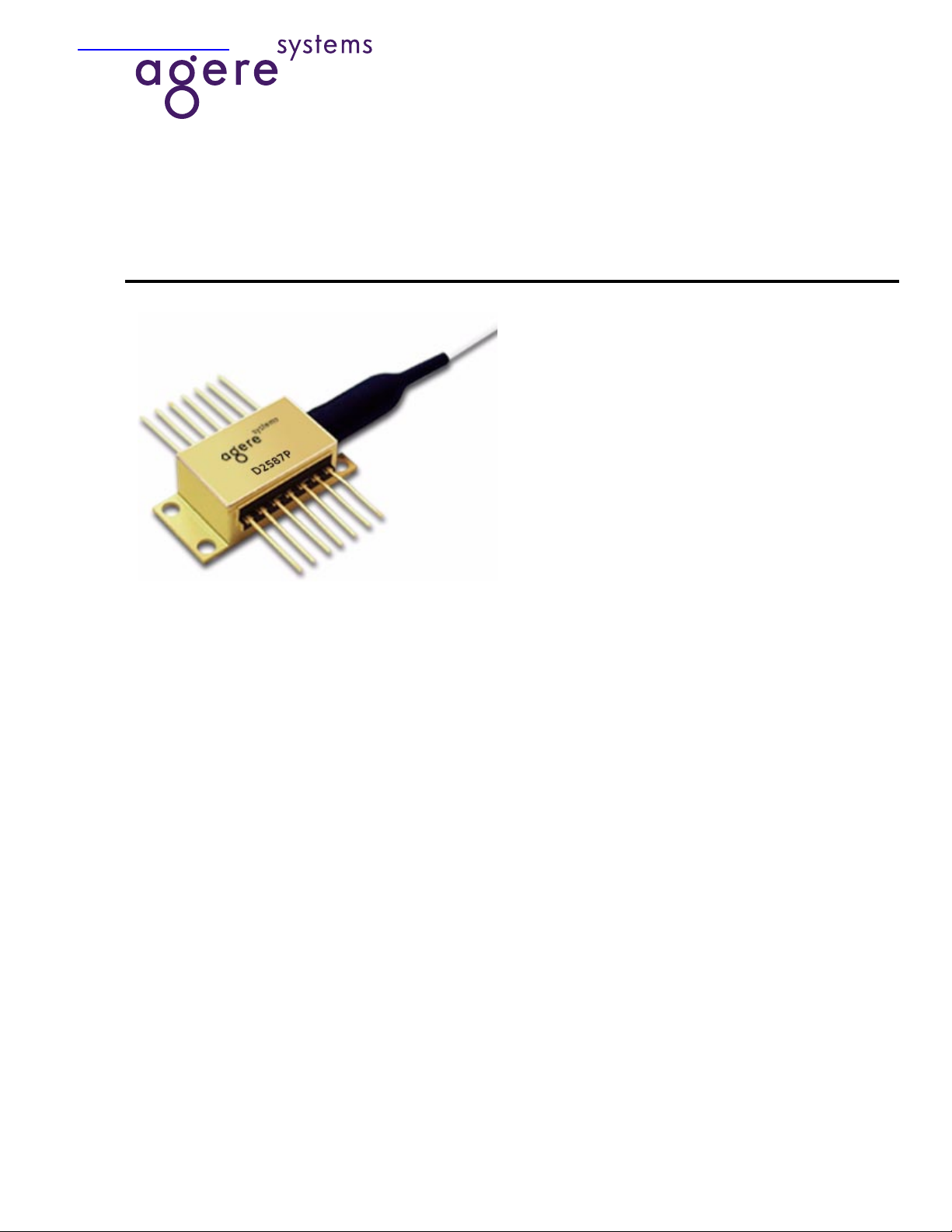
Wavelength-Selected High-Power D2587P-Type (with
Wavelength Locker)/D2547P-Type Isolated DFB Laser Modules
Applications
■
Telecommunications:
— Dense WDM
— SONET/SDH OC-192/STM-64
— Extended and ultralong reach
— Undersea systems
■
Digital video
Data Sheet, Rev. 2
July 2001
Featuring wavelength selection and locking capabilities, the
D2587P Laser Module is ideally suited for use with external
lithium niobate modulators, and in high-power (20 mW) applications.
Features
■
High-performance, multiquantum-well (MQW),
distributed-feedback (DFB) laser
■
D2587P-Type is offered on 50 GHz ITU grid
wavelengths ranging from 1528.77 nm—
1610.06 nm
■
D2547P-Type is offered on 100 GHz ITU grid
wavelengths ranging from 1528.77 nm—
1610.06 nm
■
Polarization-maintaining fiber pigtail
■
For use with lithium niobate modulators
Description
The D2587P-Type DFB laser module is designed for
use with an external lithium niobate modulator and
also in applications where high power (20 mW) is
required.
The use of an internal wavelength locker greatly
enhances long-term reliability and reduces chirp and
mode dispersion when used in conjunction with LN
modulators at OC-192 data rates.
A companion device, the D2547P high-power DFB
laser module, is also designed for use with a lithium
niobate external modulator, but without the use of an
internal wavelength locker.
■
High optical power (20 mW, CW)
■
Hermetic, 14-pin package
Page 2
Wavelength-Selected, High-Power D2587P-Type (with Wavelength Data Sheet, Rev. 2
Locker)/D2547P-Type Isolated DFB Laser Modules July 2001
Description
(continued)
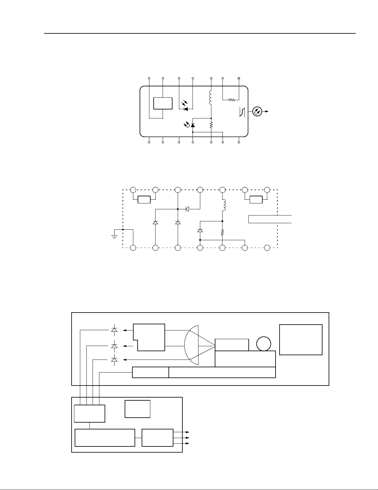
Principles of Operation (Controlled W avelength)
The single-channel, wavelength-selected DFB (ILM) package contains internal wavelength-disc riminating optics , i.e . ,
two etalons and associated photodiodes. The output consists of analog signals suitable for controlling the electrical
current of the thermoelectric cooler (TEC) and the DFB
laser.
Controlled Feedback
The module contains an internal optical isolator that suppresses optical feed back in laser-based, fiber-optic systems. Light reflected back to the laser is attenuated a
minimum of 30 dB.
Controlled Temperature
An integral TEC provides stable thermal characteristics.
The TEC allows for heat ing and cooling of the laser chip to
maintain a temperature of 25 °C for ca se temperatures fro m
–25 °C to +70 °C. The laser temperature is monitored by
the internal thermistor, which can be used with external circuitry to control the laser chip temperature.
Agere Systems’ optoelectronic components are being qualified to rigorous internal standards that are consistent with
Telcordia Technologies
manufacturing oper ations are
†
TR-NWT-000468. All design and
§
9001 certified. The
ISO
module is being fully qualified for central office applications.
*
†
§
is a registered trademark of Fujikura Ltd.
Fujikura
Telcordia Technologies
Inc.
is a registered trademark of The International Organization for
ISO
Standardization.
is a trademark of Telcordia Technologies
CORE
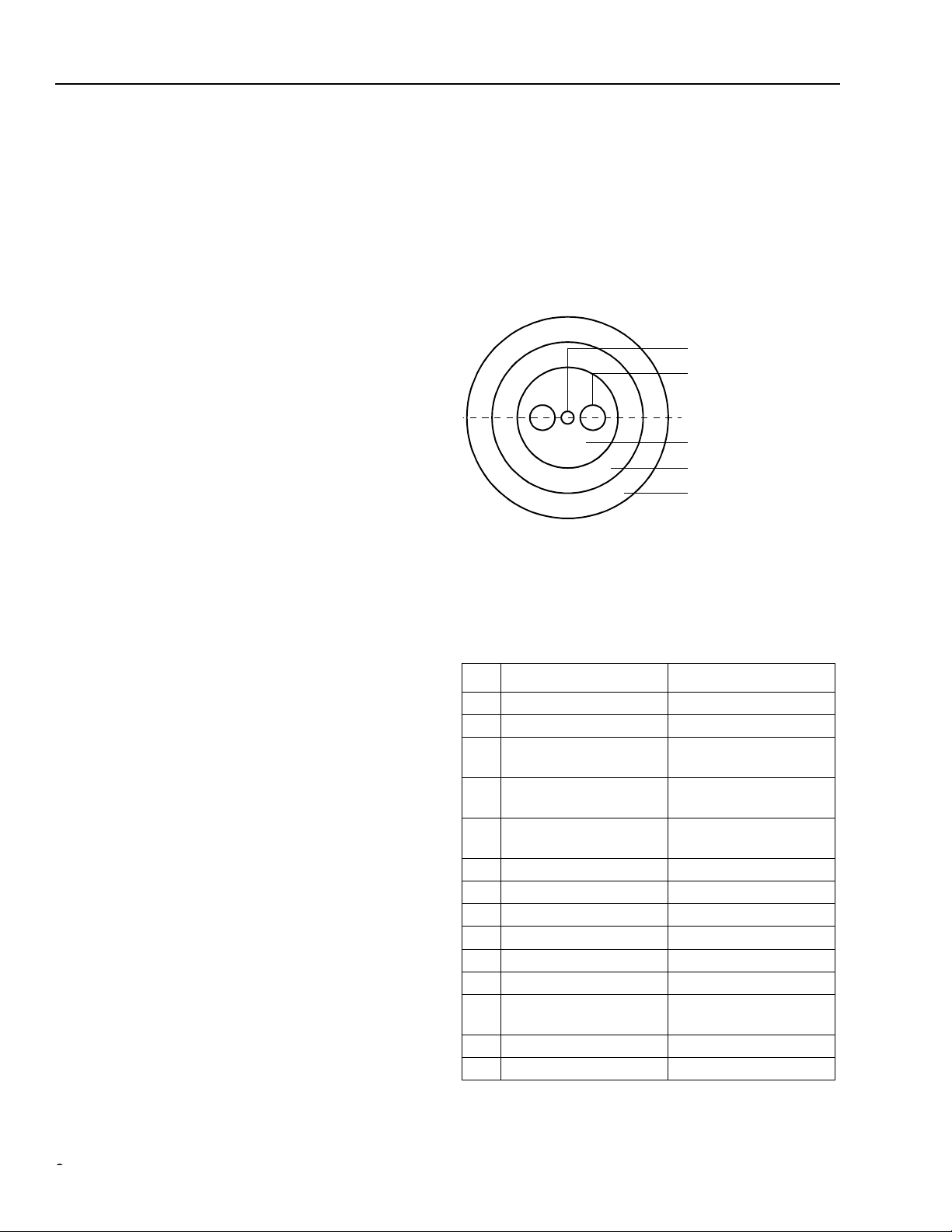
STRESS ROD
PRINCIPLE POLARIZATION
AXIS
CLADDING
INNER COATING
(SILICON & ACRYLATE)
OUTER COAT ING
1-771(C).a
Figure 1. Polarization-Maintaining Fiber
Pin Information
Table 1. Pin Descriptions
Controlled Power
An internal, InGaAs, PIN photodiode functions as the backfacet monitor. The photodiode monitors emission from the
rear facet of the laser and, when used in conjun ct io n with
control circuitry, can control optic al power launched into the
fiber. Normally, this configuration is used in a feedbac k
arrangement to maintain consistent laser output power.
Standard Package
The laser module is fabricated in a 14-pin, hermetic, metal/
ceramic butterfly package that incorporates a bias tee that
separates the dc-bias p ath from the RF input. The RF input
has a nominal 25 Ω impedance.
The laser module is equipped with
Fujikura
maintaining fiber (PMF). The fiber is PANDA type an d is the
same fiber that is used on the Agere Systems Inc. lithium
niobate modulators. It has a mode field diameter of
10.5 µm, a cladding diameter of 125µm ±3 µm, and a
loose tube jacketed fiber 900 µm in diameter. Figure 1
shows the orientation of polarization in the fiber.
* polarization-
Pin D2587P-Type D2547P-Type
1 Thermistor Thermistor
2 Thermistor Thermistor
3 Laser dc Bias
(Cathode) (–)
4 Back-facet Monitor
Anode (–)
5 Back-facet Monitor
Cathode (+)
6TEC (+)
7TEC (–)
1
1
Laser dc Bias
(Cathode) (–)
Back-facet Monitor
Anode (–)
Back-facet Monitor
Cathode (+)
TEC (+)
TEC (–)
1
1
8 Case Ground Case Ground
9
Photodiode 2 Anode
λ
10λ Photodiode 1 Anode
11 Laser Anode (+)
2
12 RF Laser Input
Cathode (–)
13 Laser Anode (+)
2
14 NC
1.A positive current through the thermoelectric heat pump cools the
laser.
2.Both leads should be grounded for optimum performance.
Case Ground
Case Ground
Laser Anode (+)
RF Laser Input
Cathode (–)
Laser Anode (+)
Case Ground
2
2
22
Agere Systems Inc.
Page 3
Data Sheet, Rev. 2 Wavelength-Selected, High-Power D2587P-Type (with Wavelength
July 2001 Locker)/D2547P-Type Isolated DFB Laser Modules
Description
(continued)
76 54 32 1
–+ +– –
L1
TEC
PACKAGE
GROUNDS
8 9 10 11 12 13
140 nH
+–+
R1
20
TH
10 k
ISOLATOR
Ω
Ω
NC
14
1-567
Top view .
Figure 2. D2547P Circuit Schematic
7654321
R
TEC
PD
WAVE
PD
WAVE
PD
POWER
LD
RFC
R
RF
TH
PM FIBER PIGTAIL
Block Diagram
A TO D
CONVERTER
MICROPROCESSOR
8 9 10 11 12 13 14
Figure 3. D2587P Circuit Schematic
DUAL
ETALON
THERMISTOR
EEPROM
D TO A
CONVERTER
THERMOELECTRIC COOLER
SUGGESTED
ELECTRONICS MODULE (CUSTOMER SUPPLIED)
VOLTAGE PROPORTIONAL TO WAVELENGTH
VOLTAGE PROPORTIONAL TO OPTICAL POWER
VOLTAGE PROPORTIONAL TO TEMPERATURE
DFB
SILICON SUBMOUNT
1-1130(F)
LASER MODULE
ISOLATOR AND
FIBER COUPLING
OPTICS
Agere Systems Inc.
1-1129(F)
3
Page 4
Wavelength-Selected, High-Power D2587P-Type (with Wavelength Data Sheet, Rev. 2
Locker)/D2547P-Type Isolated DFB Laser Modules July 2001
Absolute Maximum Ratings
Stresses in excess of the absolute maximum ratings can cause permanent damage to the device. These are absolute stress ratings only. Functional operation of the device is not implied at these or any other conditions in excess
of those given in the operations sections of the data sheet. Exposure to absolute maximum ratings for extended
periods can adversely affect device reliability.
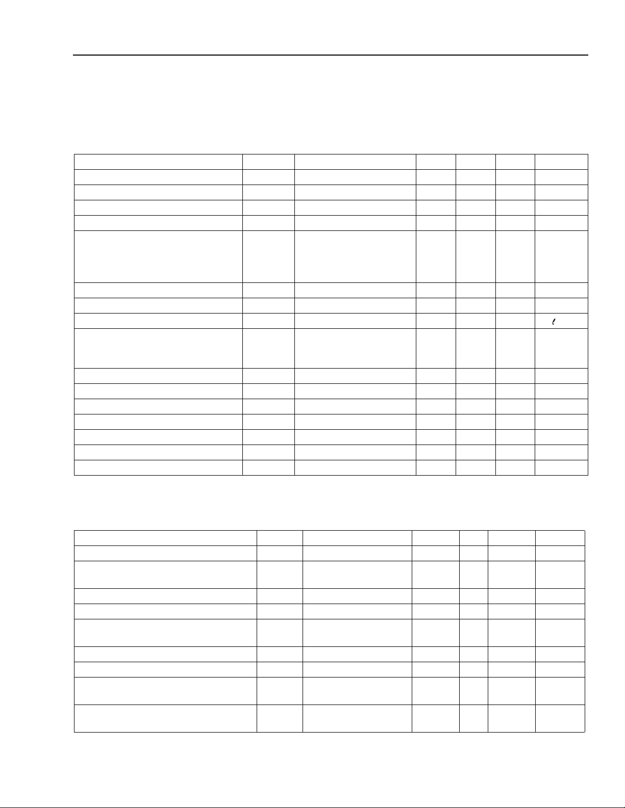
Parameter Symbol Min Max Unit
Laser Reverse Voltage V
dc Forward Current I
Operating Case Temperature Range T
Storage Case Temperature Range* T
Photodiode Reverse Vo lta ge V
Photodiode Forward Current I
* Does not apply to shipping container.
RLMAX
FLMAX
C
stg
RPDMAX
FPDMAX
—2 V
— 225 mA
–25 70 °C
–40 70 °C
—10 V
—2 mA
Handling Precautions
Power Sequencing
To avoid the possibility of damage to the laser module
from power supply switching transients, follow this
turn-on sequence:
1. All ground connections
2. Most negative supply
3. Most positive supply
4. All remaining connections
Reverse the order for the proper turn-off sequence.
Electrostatic Discharge
CAUTION: This device is susceptible to damage as
a result of electrostatic discharge. Take
proper precautions during both handling and testing. Follow guidelines
such as JEDEC Publication No. 108-A
(Dec. 1988).
Agere Systems employs a human-body model (HBM)
for ESD-susceptibility testing and protection-design
evaluation. ESD voltage thresholds are dependent on
the critical parameters used to define the model. A
standard HBM (resistance = 1.5 kΩ, capacitance = 100
pF) is widely used and, therefore, can be used for comparison purposes. The HBM ESD threshold presented
here was obtained using these circuit parameters:
Mounting Instructions
The minimum fiber bend radius is 1.0 in. (25.4 mm)
To avoid degradation in performance, mount the mod-
ule on the board as follows:
1. Place the bottom flange of the module on a flat heat
sink at least 0.5 in. x 1.180 in. (12.7 mm x 30 mm) in
size. The surface finish of the heat sink should be
better than 32 µin. (0.8 µm), and the surface flatness
must be better than 0.001 in. (25.4 µm). Using thermal conductive grease is optional; however, thermal
performance can be improved by up to 5% if conductive grease is applied between the bottom flange and
the heat sink.
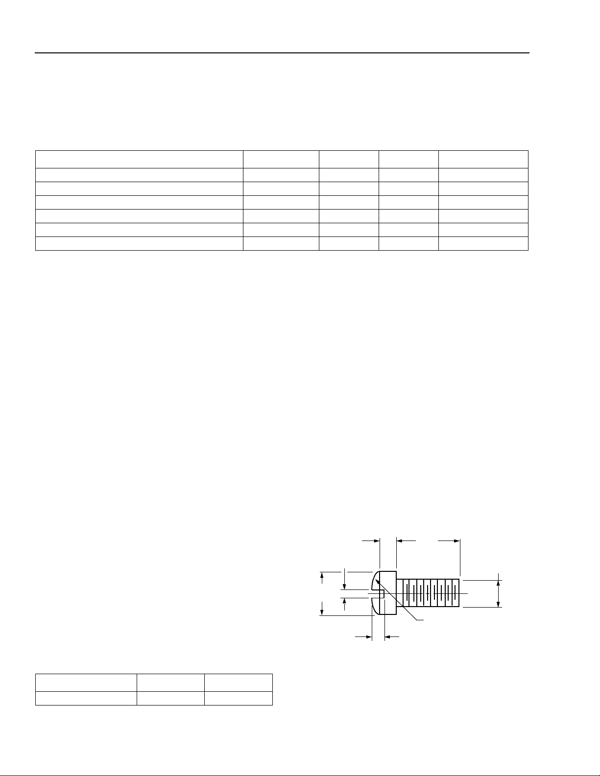
2. Mount four #2-56 screws with Fillister heads
(M2-3 mm) at the four screw hole locations (see Outline Diagram). The Fillister head diameter must not
exceed 0.140 in. (3.55 mm). Do not apply more than
1 in.-lb. of torque to the screws.
0.062 (1.58)
0.031 (0.79)
0.140
(3.56)
Note: Dimensions are in inches and (millimeters).
0.118
(3.00)
0.086
(2.18)
0.129 (3.28) R
0.041 (1.04)
1-532(C)
Parameter Value Unit
Human-body Model >400 V
4
Figure 4. Fillister Head Screw
Agere Systems Inc.
Page 5
Data Sheet, Rev. 2 Wavelength-Selected, High-Power D2587P-Type (with Wavelength
July 2001 Locker)/D2547P-Type Isolated DFB Laser Modules
Characteristics
Minimum and maximum values are testing requirements. Typical values are device characteristics and are results
of engineering evaluations; they are for information purposes only and are not part of the testing requirements.
Table 2. D2587-Type Electrical Characteristics
(at 25 °C laser temperature)
Parameter Symbol Test Conditions Min Typ Max Unit
Threshold Current I
TH
Drive Current — L
RMON
RMON
I
λ
PD1
I
λ
PD2
I
LF
D
IN
LF = 20 mW (CW) — 2 2.5 V
PO = 20 mW (CW)
IF = 0, V
Laser Forward Voltage V
Monitor Reverse-bias Voltage* V
Monitor Current:
Back-facet Monitor
Photodiode 1
λ
Photodiode 2
λ
Monitor Dark Current I
Input Impedance Z
— — 15 40 mA
F
= 20 mW — — 165 mA
—3510V
0.003
0.003
0.003
RMON
= 5 V — 0.01 0.1 µA
—
—
—
0.06
0.06
0.06
——25—Ω
Filter Slope — — 0.5 — 8 /nm
Frequency Capture Range — Measured from λ
ITU
15 — — GHz
toward increasing λ and
decreasing λ
Thermistor Current I
Resistance Ratio
†
Thermistor Resistance R
Laser Submount Temperature T
TEC Current I
TEC Voltage V
TEC Capacity ∆TT
TC
— 10 — 100 µA
— — 9.1 9.6 10.1 —
TH
SET
TEC
TEC
TL = 25 °C 9.5 — 10.5 kΩ
—20—35°C
TL = 25 °C, TC = 70 °C — — 1.7 A
TL = 25 °C, TC = 70 °C — — 2.8 V
C
= 70 °C — 50 °C
mA
mA
mA
* S tandard operating condition is 5.0 V reverse bias.
† Ratio of thermistor resistance at 0 °C to thermistor resistance at 50 °C.
Table 3. D2587-Type Optical Characteristics
(at 25 °C laser temperature)
Parameter Symbol Test Conditions Min Typ Max Unit
Peak Optical Output Power P
Center Wavelength*
(See Ordering Information, page 9.)
Line Width (3 dB full width) ∆λ CW, P
P
C
λ
λ
—20.0——mW
SET
TL = T
C
ITU
= λ
± 0.1 nm
F
= 20.0 mW — 2 10 MHz
1528.77 — 1610.06 nm
Side-mode Suppression Ratio SMSR CW 35 45 — dB
Relative Intensity Noise RIN CW, P
= 20 mW
F
— — –135 dB/Hz
200 MHz < f < 10 GHz
Optical Isolation — T
Optical Polarization Extinction Ratio
†
— 0 °C to 75 °C 20 — — dB
FM Efficiency FM f
Wavelength Drift (EOL) ∆λ
C
C
= 0 °C to 75 °C 30 — — dB
MOD
= 30 kHz,
F
P
= 20 mW
Tested over
—100—MHz/mA
——±2.5GHz
25-year lifeti me
* Custom wavelengths available.
† The
®
ST
ferrule key is not aligned to slow axis of fiber. Connector is intended for testing purposes only.
Agere Systems Inc.
5
Page 6

Wavelength-Selected, High-Power D2587P-Type (with Wavelength Data Sheet, Rev. 2
Locker)/D2547P-Type Isolated DFB Laser Modules July 2001
Characteristics
(continued)
Minimum and maximum values are testing requirements. Typical values are device characteristics and are results
of engineering evaluations; they are for information purposes only and are not part of the testing requirements.
Table 4. D2547P-Type Electrical Characteristics
(at 25 °C laser temperature)
Parameter Symbol Test Conditions Min Typ Max Unit
Threshold Current I
TH
Drive Current — L
Laser Forward Voltage V
Monitor Reverse-bias Vol tage * V
Back-facet Monitor Current: I
Monitor Dark Current I
Input Impedance Z
Thermistor Current I
Resistance Ratio
†
Thermistor Resistance R
Laser Submount Temperature T
TEC Current I
TEC Vo ltage V
LF
RMON
RMON
D
IN
TC
LF = 20 mW (CW) — 2 2.5 V
PO = 20 mW (CW) 0.2 — — mA
IF = 0, V
— — 9.1 9.6 10.1 —
TH
LASER
TEC
TEC
TL = 25 °C, TC = 70 °C — — 1.7 A
TL = 25 °C, TC = 70 °C — — 2.8 V
TEC Capacity ∆TT
— — 15 40 mA
F
= 20 mW — — 165 mA
—3510V
RMON
= 5 V — 0.01 0.1 µA
——25—Ω
—10—100µA
TL = 25 °C 9.5 — 10.5 kΩ
— 20 — 35 °C
C
= 70 °C — — 50 °C
* Standard operating condition is 5.0 V reverse bias.
† Ratio of thermistor resistance at 0 °C to thermistor resistance at 50 °C.
Table 5. D2547P-Type Optical Characteristics
(at 25 °C laser temperature)
Parameter Symbol Test Conditions Min Typ Max Unit
Peak Optical Output Power P
Center Wavelength*
(See Ordering Information,
P
C
λ
λ
—20.0——mW
SET
C
TL = T
= λ
ITU
± 0.1 nm
1528.77 — 1610.06 nm
page 12.)
F
Line Width (3 dB full width) ∆λ CW, P
= 20.0 mW — 2 10 MHz
Side-mode Suppression Ratio SMSR CW 35 45 — dB
Relative Intensity Noise RIN CW, P
= 20 mW
F
— — –135 dB/Hz
200 MHz < f < 10 GHz
Optical Isolation — T
Optical Polarization Extinction
†
Ratio
— 0 °C to 75 °C 20 — — dB
FM Efficiency FM f
Wavelength Drift (EOL) ∆λ
C
C
= 0 °C to 75 °C 30 — — dB
MOD
= 30 kHz,
F
P
= 20 mW
Tested over
— 100 — MHz/mA
——±0.1 nm
25-year lifetime
* Custom wavelengths available.
ST
† The
ferrule key is not aligned to slow axis of fiber. Connector is intended for testing purposes only.
6
Agere Systems Inc.
Page 7

Data Sheet, Rev. 2 Wavelength-Selected, High-Power D2587P-Type (with Wavelength
July 2001 Locker)/D2547P-Type Isolated DFB Laser Modules
Characteristics
(continued)
Table 6. D2587P/D2547P Fiber Pigtail and Optical Connector Characteristics
Parameter Symbol Description Min Typ Max Unit
Pigtail Length L
Fujikura
PANDA or equivalent
1.5 — — m
polarization-maintaining fiber
Connector Style —
ST
plug (FC/PC optional) — — — —
Outline Diagram
Dimensions are in inches and (millimeters). Tolerances are ±0.005 in. (±0.127 mm).
0.605
(15.37)
MAX
0.500 (12.70)
MIN
0.500
(12.70)
0.350
(8.89)
1.025 (26.04)
0.020 (0.51) TYP
~
PIN 1
TRADEMARK, CODE, LASER SERIAL NUMBER,
AND DATE CODE IN APPROX. AREA SHOWN
STRAIN
RELIEF
0.10 ± 0.002
(2.54 ± 0.051)
0.036
(0.91)
0.200
(5.08)
0.365
(9.27)
MAX
0.105 (2.67) DIA
TYP (4) PLACES
0.180 (4.56)
0.056 (1.42)
0.215 (5.45)
0.100 (2.54) TYP
0.820 (20.83)
0.700 (17.78)
1.180 (29.97)
2.03 (51.6)
HEAT SINK
0.078 (1.98)
PIN 14
0.213 (5.40) TYP
0.863 (21.91)
0.575 (14.61)
0.030 (0.75)
59.06 (1500.00)
MIN
0.10
(2.5)
0.215
(5.47)
REF
0.260 (6.60)
1-520.h
Agere Systems Inc.
7
Page 8

Wavelength-Selected, High-Power D2587P-Type (with Wavelength Data Sheet, Rev. 2
Locker)/D2547P-Type Isolated DFB Laser Modules July 2001
High-Power Product
Class IIIb Laser Product
FDA/CDRH Class IIIb laser product. All versions are Class IIIb laser products per CDRH, 21 CFR 1040 Laser
Safety requirements. The device has been classified with the FDA under accession number 8720010.
This product complies with 21 CFR 1040.10 and 1040.11.
8 µm/125 µm ±3 µm single-mode fiber with 900 µm loose-tube jacketed fiber and connector
Wavelength = 1.5 µm
Maximum power = 40 mW
Because of size constraints, laser safety labeling (including an FDA Class IIIb label) is not affixed to the module but
attached to the outside of the shipping carton.
Product is not shipped with power supply.
Caution: Use of controls, adjustments, and procedures other than those specified herein may result in
hazardous laser radiation exposure.
DANGER
INVISIBLE LASER RADIATION
IS EMITTED FROM THE END
OF FIBER OR CONNECTOR
Avoid direct exposure to beam
Do not view beam directly with
optical instruments
INVISIBLE LASER RADIATION EMITTED FROM END OF FIBER OR CONNECTOR
Class IIIb Laser Product FDA/CDRH, 21 CFR 1040 Max. Output: 40 mW Wavelength: 1.5 µm
Avoid exposure to beam
8
Agere Systems Inc.
Page 9

Data Sheet, Rev. 2 Wavelength-Selected, High-Power D2587P-Type (with Wavelength
July 2001 Locker)/D2547P-Type Isolated DFB Laser Modules
Ordering Information
Table 7. D2587P 20 mW CW Laser with Locker (C- and L-Band) Ordering Information
Device
Code
ITU-T
Frequency
(THz)
D2587P61 196.1 1528.77 108835422 D2587P41 194.1 1544.53 108835620
D2587P605 196.05 1529.16 108875220 D2587P405 194.05 1544.92 108875444
D2587P60 196.0 1529.55 108835430 D2587P40 194.0 1545.32 108835638
D2587P595 195.95 1529.94 108875238 D2587P395 193.95 1545.72 108875451
D2587P59 195.9 1530.33 108835448 D2587P39 193.9 1546.12 108835646
D2587P585 195.85 1530.72 108875246 D2587P385 193.85 1546.52 108875469
D2587P58 195.8 1531.12 108835455 D2587P38 193.8 1546.92 108835653
D2587P575 195.75 1531.51 108875253 D2587P375 193.75 1547.32 108875477
D2587P57 195.7 1531.90 108835463 D2587P37 193.7 1547.72 108835661
D2587P565 195.65 1532.29 108875261 D2587P365 193.65 1548.11 108875485
D2587P56 195.6 1532.68 108835471 D2587P36 193.6 1548.51 108835679
D2587P555 195.55 1533.07 108875279 D2587P355 193.55 1548.91 108875493
D2587P55 195.5 1533.47 108835489 D2587P35 193.5 1549.32 108835687
D2587P545 195.45 1533.86 108875287 D2587P345 193.45 1549.72 108875501
D2587P54 195.4 1534.25 108835497 D2587P34 193.4 1550.12 108835695
D2587P535 195.35 1534.64 108875303 D2587P335 193.35 1550.52 108875519
D2587P53 195.3 1535.04 108835505 D2587P33 193.3 1550.92 108835703
D2587P525 195.25 1535.43 108875311 D2587P325 193.25 1551.58 108875527
D2587P52 195.2 1535.82 108835513 D2587P32 193.2 1551.72 108835711
D2587P515 195.15 1536.22 108875329 D2587P315 193.15 1552.12 108875535
D2587P51 195.1 1536.61 108835521 D2587P31 193.1 1552.52 108835729
D2587P505 195.05 1537.00 108875345 D2587P305 193.05 1552.93 108875543
D2587P50 195.0 1537.40 108835539 D2587P30 193.0 1553.33 108835737
D2587P495 194.95 1537.79 108875352 D2587P295 192.95 1553.73 108875550
D2587P49 194.9 1538.19 108835547 D2587P29 192.9 1554.13 108835745
D2587P485 194.85 1538.58 108875360 D2587P285 192.85 1554.54 108875568
D2587P48 194.8 1538.98 108835554 D2587P28 192.8 1554.94 108835752
D2587P475 194.75 1539.37 108875378 D2587P275 192.75 1555.34 108875576
D2587P47 194.7 1539.77 108835562 D2587P27 192.7 1555.75 108835760
D2587P465 194.65 1540.16 108875386 D2587P265 192.65 1556.15 108875584
D2587P46 194.6 1540.56 108835570 D2587P26 192.6 1556.55 108835778
D2587P455 194.55 1540.95 108875394 D2587P255 192.55 1556.96 108875592
D2587P45 194.5 1541.35 108835588 D2587P25 192.5 1557.36 108835786
D2587P445 194.45 1541.75 108875402 D2587P245 192.45 1557.77 108875600
D2587P44 194.4 1542.14 108835596 D2587P24 192.4 1558.17 108835794
D2587P435 194.35 1542.54 108875410 D2587P235 192.35 1558.58 108875618
D2587P43 194.3 1542.94 108835604 D2587P23 192.3 1558.98 108835802
D2587P425 194.25 1543.33 108875428 D2587P225 192.25 1559.39 108875626
D2587P42 194.2 1543.73 108835612 D2587P22 192.2 1559.79 108835810
D2587P415 194.15 1544.13 108875436 D2587P215 192.15 1560.20 108875634
Center
Wavelength
(nm)
Comcode Device
Code
ITU-T
Frequency
(THz)
(continued)
Center
Wavelength
(nm)
Comcode
Agere Systems Inc.
9
Page 10

Wavelength-Selected, High-Power D2587P-Type (with Wavelength Data Sheet, Rev. 2
Locker)/D2547P-Type Isolated DFB Laser Modules July 2001
Ordering Information
Table 7. D2587P 20 mW CW Laser with Locker (C- and L-Band) Ordering Information
Device
Code
D2587P21 192.1 1560.61 108835828 D2587P900 190.0 1577.86 108836990
D2587P205 192.05 1561.01 108875642 D2587P8995 189.95 1578.27 108876079
D2587P20 192.0 1561.42 108835836 D2587P899 189.9 1578.69 108836982
D2587P195 191.95 1561.83 108875659 D2587P8985 189.85 1579.10 108876061
D2587P19 191.9 1562.23 108835844 D2587P898 189.8 1579.52 108836974
D2587P185 191.85 1562.64 108875667 D2587P8975 189.75 1579.93 108876046
D2587P18 191.8 1563.05 108835851 D2587P897 189.7 1580.35 108836511
D2587P175 191.75 1563.45 108875675 D2587P8965 189.65 1580.77 108876038
D2587P17 191.7 1563.86 108835869 D2587P896 189.6 1581.18 108836503
D2587P9165 191.65 1564.27 109976244 D2587P8955 189.55 1581.60 108876020
D2587P916 191.6 1564.68 108838418 D2587P895 189.5 1582.02 108836495
D2587P9155 191.55 1565.09 108876236 D2587P8945 189.45 1582.44 108876012
D2587P915 191.5 1565.50 108838400 D2587P894 189.4 1582.85 108836487
D2587P9145 191.45 1565.90 108876228 D2587P8935 189.35 1583.27 108876004
D2587P914 191.4 1566.31 108837139 D2587P893 189.3 1583.69 108836479
D2587P9135 191.35 1566.72 108876210 D2587P8925 189.25 1584.11 108875980
D2587P913 191.3 1567.13 108837121 D2587P892 189.2 1584.53 108836461
D2587P9125 191.25 1567.54 108876202 D2587P8915 189.15 1584.95 108875972
D2587P912 191.2 1567.95 108837113 D2587P891 189.1 1585.36 108836453
D2587P9115 191.15 1568.36 108876194 D2587P8905 189.05 1585.78 108875964
D2587P911 191.1 1568.77 108837105 D2587P890 189.0 1586.20 108836446
D2587P9105 191.05 1569.18 108876186 D2587P8895 188.95 1586.62 108875956
D2587P910 191.0 1569.59 108837097 D2587P889 188.9 1587.04 108836438
D2587P9095 190.95 1570.01 108876178 D2587P8885 188.85 1587.46 108875949
D2587P909 190.9 1570.42 108837089 D2587P888 188.8 1587.88 108836420
D2587P9085 190.85 1570.83 108876160 D2587P8875 188.75 1588.30 108875931
D2587P908 190.8 1571.24 108837071 D2587P887 188.7 1588.72 108836412
D2587P9075 190.75 1571.65 108876152 D2587P8865 188.65 1589.15 108875923
D2587P907 190.7 1572.06 108837063 D2587P886 188.6 1589.57 108836404
D2587P9065 190.65 1572.48 108876145 D2587P8855 188.55 1589.99 108875915
D2587P906 190.6 1572.89 108837055 D2587P885 188.5 1590.41 108836396
D2587P9055 190.55 1573.30 108876137 D2587P8845 188.45 1590.83 108875907
D2587P905 190.5 1573.71 108837048 D2587P884 188.4 1591.26 108836388
D2587P9045 190.45 1574.13 108876129 D2587P8835 188.35 1591.68 108875899
D2587P904 190.4 1574.54 108837030 D2587P883 188.3 1592.10 108836370
D2587P9035 190.35 1574.95 108876111 D2587P8825 188.25 1592.52 108875881
D2587P903 190.3 1575.37 108837022 D2587P882 188.2 1592.95 108836362
D2587P9025 190.25 1575.78 108876103 D2587P8815 188.15 1593.37 108875873
D2587P902 190.2 1576.20 108837014 D2587P881 188.1 1593.79 108836354
D2587P9015 190.15 1576.61 108876095 D2587P8805 188.05 1594.22 108875865
D2587P901 190.1 1577.03 108837006 D2587P880 188.0 1594.64 108836347
D2587P9005 190.05 1577.44 108876087 D2587P8795 187.95 1595.06 108875857
10
ITU-T
Frequency
(THz)
(continued)
Center
Wavelength
(nm)
Comcode Device
Code
ITU-T
Frequency
(THz)
(continued)
Center
Wavelength
(nm)
Comcode
Agere Systems Inc.
Page 11

Data Sheet, Rev. 2 Wavelength-Selected, High-Power D2587P-Type (with Wavelength
July 2001 Locker)/D2547P-Type Isolated DFB Laser Modules
Ordering Information
Table 7. D2587P 20 mW CW Laser with Locker (C- and L-Band) Ordering Information
Device
Code
D2587P879 187.9 1595.49 108836339 D2587P870 187.0 1603.17 108835950
D2587P8785 187.85 1595.91 108875840 D2587P8695 186.95 1603.60 108875758
D2587P878 187.8 1596.34 108836321 D2587P869 186.9 1604.03 108835943
D2587P8775 187.75 1596.76 108875832 D2587P8685 186.85 1604.46 108875741
D2587P877 187.7 1597.19 108836313 D2587P868 186.8 1604.88 108835935
D2587P8765 187.65 1597.62 108875824 D2587P8675 186.75 1605.31 108875733
D2587P876 187.6 1598.04 108836016 D2587P867 186.7 1605.74 108835927
D2587P8755 187.55 1598.47 108875816 D2587P8665 186.65 1606.17 108875725
D2587P875 187.5 1598.89 108836008 D2587P866 186.6 1606.60 108835919
D2587P8745 187.45 1599.32 108875808 D2587P8655 186.55 1607.04 108875717
D2587P874 187.4 1599.75 108835992 D2587P865 186.5 1607.47 108835901
D2587P8735 187.35 1600.17 108875790 D2587P8645 186.45 1607.90 108875709
D2587P873 187.3 1600.60 108835984 D2587P864 186.4 1608.33 108835893
D2587P8725 187.25 1601.03 108875782 D2587P8635 186.35 1608.76 108875691
D2587P872 187.2 1601.46 108835976 D2587P863 186.3 1609.19 108835885
D2587P8715 187.15 1601.88 108875774 D2587P8625 186.25 1609.62 108875683
D2587P871 187.1 1602.31 108835968 D2587P862 186.2 1610.06 108835877
D2587P8705 187.05 1602.74 108875766
ITU-T
Frequency
(THz)
(continued)
Center
Wavelength
(nm)
Comcode Device
Code
ITU-T
Frequency
(THz)
(continued)
Center
Wavelength
(nm)
Comcode
Agere Systems Inc.
11
Page 12

Wavelength-Selected, High-Power D2587P-Type (with Wavelength Data Sheet, Rev. 2
Locker)/D2547P-Type Isolated DFB Laser Modules July 2001
Ordering Information
Table 8. D2547P 20 mW CW Laser without Locker (C-Band)
Device
Code
D2547P61 196.1 1528.77 108838301 D2547P38 193.8 1546.92 108838079
D2547P60 196.0 1529.55 108838293 D2547P37 193.7 1547.72 108838061
D2547P59 195.9 1530.33 108838285 D2547P36 193.6 1548.51 108838053
D2547P58 195.8 1531.12 108838277 D2547P35 193.5 1549.32 108838046
D2547P57 195.7 1531.90 108838269 D2547P34 193.4 1550.12 108838038
D2547P56 195.6 1532.68 108838251 D2547P33 193.3 1550.92 108838020
D2547P55 195.5 1533.47 108838244 D2547P32 193.2 1551.72 108838012
D2547P54 195.4 1534.25 108838236 D2547P31 193.1 1552.52 108838004
D2547P53 195.3 1535.04 108838228 D2547P30 193.0 1553.33 108837998
D2547P52 195.2 1535.82 108838210 D2547P29 192.9 1554.13 108837980
D2547P51 195.1 1536.61 108838202 D2547P28 192.8 1554.94 108837972
D2547P50 195.0 1537.40 108838194 D2547P27 192.7 1555.75 108837964
D2547P49 194.9 1538.19 108838186 D2547P26 192.6 1556.55 108837956
D2547P48 194.8 1538.98 108838178 D2547P25 192.5 1557.36 108837949
D2547P47 194.7 1539.77 108838160 D2547P24 192.4 1558.17 108837931
D2547P46 194.6 1540.56 108838152 D2547P23 192.3 1558.98 108837923
D2547P45 194.5 1541.35 108838145 D2547P22 192.2 1559.79 108837915
D2547P44 194.4 1542.14 108838137 D2547P21 192.1 1560.61 108837907
D2547P43 194.3 1542.94 108838129 D2547P20 192.0 1561.42 108837899
D2547P42 194.2 1543.73 108838111 D2547P19 191.9 1562.23 108837881
D2547P41 194.1 1544.53 108838103 D2547P18 191.8 1563.05 108837873
D2547P40 194.0 1545.32 108838095 D2547P17 191.7 1563.86 108837865
D2547P39 193.9 1546.12 108838087
ITU-T
Frequency
(THz)
(continued)
Center
Wa velength
(nm)
Comcode
Device
Code
ITU-T
Frequency
(THz)
Center
Wavelength
(nm)
Comcode
12
Agere Systems Inc.
Page 13

Data Sheet, Rev. 2 Wavelength-Selected, High-Power D2587P-Type (with Wavelength
July 2001 Locker)/D2547P-Type Isolated DFB Laser Modules
Ordering Information
Table 9. D2547P 20 mW CW Laser without Locker (L-Band) Ordering Information
Device
Code
D2547P916 191.6 1564.68 108837840 D2547P888 188.8 1587.88 108837568
D2547P915 191.5 1565.50 108837832 D2547P887 188.7 1588.73 108837394
D2547P914 191.4 1566.31 108837824 D2547P886 188.6 1589.57 108837386
D2547P913 191.3 1567.13 108837816 D2547P885 188.5 1590.41 108837378
D2547P912 191.2 1567.95 108837808 D2547P884 188.4 1591.26 108837360
D2547P911 191.1 1568.77 108837790 D2547P883 188.3 1592.10 108837352
D2547P910 191.0 1569.59 108837782 D2547P882 188.2 1592.95 108837345
D2547P909 190.9 1570.42 108837774 D2547P881 188.1 1593.79 108837337
D2547P908 190.8 1571.24 108837766 D2547P880 188.0 1594.64 108837329
D2547P907 190.7 1572.06 108837758 D2547P879 187.9 1595.49 108837311
D2547P906 190.6 1572.89 108837741 D2547P878 187.8 1596.34 108837303
D2547P905 190.5 1573.71 108837733 D2547P877 187.7 1597.19 108837295
D2547P904 190.4 1574.54 108837725 D2547P876 187.6 1598.04 108837287
D2547P903 190.3 1575.37 108837717 D2547P875 187.5 1598.89 108837279
D2547P902 190.2 1576.20 108837709 D2547P874 187.4 1599.75 108837261
D2547P901 190.1 1577.03 108837691 D2547P873 187.3 1600.60 108837253
D2547P900 190.0 1577.86 108837683 D2547P872 187.2 1601.46 108837246
D2547P899 189.9 1578.69 108837675 D2547P871 187.1 1602.31 108837238
D2547P898 189.8 1579.52 108837667 D2547P870 187.0 1603.17 108837220
D2547P897 189.7 1580.35 108837659 D2547P869 186.9 1604.03 108837212
D2547P896 189.6 1581.18 108837642 D2547P868 186.8 1604.88 108837204
D2547P895 189.5 1582.02 108837634 D2547P867 186.7 1605.74 108837196
D2547P894 189.4 1582.85 108837626 D2547P866 186.6 1606.60 108837188
D2547P893 189.3 1583.69 108837618 D2547P865 186.5 1607.47 108837170
D2547P892 189.2 1584.53 108837600 D2547P864 186.4 1608.33 108837162
D2547P891 189.1 1585.36 108837592 D2547P863 186.3 1609.19 108837154
D2547P890 189.0 1586.20 108837584 D2547P862 186.2 1610.06 108837147
D2547P889 188.9 1587.04 108837576
ITU
Frequency
(THz)
(continued)
Center
Wavelength
(nm)
Comcode
Device
Code
ITU
Frequency
(THz)
Center
Wavelength
(nm)
Comcode
Agere Systems Inc.
13
Page 14

Wavelength-Selected, High-Power D2587P-Type (with Wavelength Data Sheet, Rev. 2
Locker)/D2547P-Type Isolated DFB Laser Modules July 2001
For additional information, contact your Agere Systems Account Ma na ger or the following:
INTERNET:
E-MAIL:
N. AMERICA: Agere Systems Inc., 555 Union Boulevard, Room 30L-15P-BA, Allentown, PA 18109-3286
ASIA PACIFIC: Agere Systems Singapore Pte. Ltd., 77 Science Park Drive, #03-18 Cintech III, Singapore 118256
CHINA: Agere Systems (Shanghai) Co., Ltd., 33/F Jin Mao Tower, 88 Century Boulevard Pudong, Shanghai 200121 PRC
JAPAN: Agere Systems Japan Ltd., 7-18, Higashi-Gotanda 2-chome, Shinagawa-ku, Tokyo 141, Japan
EUROPE: Data Requests: DATALINE:
Agere Systems Inc. reserves the right to make changes to the product(s) or information contained herein without notice. No liability is assumed as a result of their use or application. ST is a
registered trademark of Agere Systems Inc.
Copyright © 2001 Agere Systems Inc.
All Rights Reserved
July 2001
DS00-263OPTO-2 (Replaces DS00-263OPTO-1)
http://www.agere.com
docmaster@micro.lucent.com
1-800-372-2447
Tel. (65) 778 8833
Tel. (86) 21 50471212
Tel. (81) 3 5421 1600
Technical Inquiries: OPTOELECTRONICS MARKETING:
, FAX 610-712-4106 (In CANADA:
, FAX (65) 777 7495
, FAX (86) 21 50472266
, FAX (81) 3 5421 1700
Tel. (44) 7000 582 368
1-800-553-2448
, FAX (44) 1189 328 148
, FAX 610-712-4106)
(44) 1344 865 900
(Ascot UK)
 Loading...