

Page 1
Data Sheet
March 2000
Wavelength-Selected D2525P
Isolated DFB Laser Module with PMF
The 1.5 µ m D2525P Laser Module is available in a 14-pin, hermetic, butterfly package.
Features
■
ITU wavelengths available from
1529.55 nm —1610.06 nm
■
Integrated optical isolator
■
High-performance, multiquantum-well (MQW),
distributed-feedback (DFB) laser
■
Industry-standard, 14-pin butterfly package
■
Hermetic package
■
InGaAs, PIN photodetector back-facet monitor
■
Polarization-maintaining fiber pigtail
■
For use with lithium niobate modulators
■
High reliability
■
Narrow linewidth
■
High optical power available
Applications
■
Telecommunications
— SONET/SDH OC-48/STM-16, OC-192/STM-64
— Extended and ultralong reach
— Undersea systems
— Dense WDM systems
■
Digital video
Description
The D2525P family of DFB laser modules is
designed to be used with a lithium niobate external
modulator (see Table 4). The laser module features a
polarization-maintaining fiber (PMF) pigtail, enabling
it to be directly connected to a modulator without the
need of a polarization controller. The PMF maintains
the polarization of the output light to a consistent orientation. This allows the D2525P to be used as a CW
light source for systems requiring extremely low chirp
such as undersea or 10 Gbits/s systems. The module
contains a multiquantum-well (MQW), distributedfeedback (DFB) laser. This device nominally has an
output power of 10 mW. The wavelength of the laser
can be temperature-tuned for more precise wavelength selection by adjusting the temperature of the
internal thermoelectric cooler.
Page 2
Wavelength-Selected D2525P Data Sheet
Isolated DFB Laser Module with PMF March 2000
22
Lucent Technologies Inc.
Description
(continued)
Controlled Feedback
The module contains an internal optical isolator that suppresses optical feedback in laser-based, fiber-optic systems. Light reflected back to the laser is attenuated a
minimum of 30 dB.
Controlled T emperature
An integral thermoelectric cooler (TEC) provides stable
thermal characteristics. The TEC allows for heating and
cooling of the laser chip to maintain a temperature of 25
°
C
for case temperatures from –40
°
C to +70 ° C. The laser
temperature is monitored by the internal thermistor, which
can be used with external circuitry to control the laser chip
temperature.
Controlled Power
An internal, InGaAs, PIN photodiode functions as the backfacet monitor. The photodiode monitors emission from the
rear facet of the laser and, when used in conjunction with
control circuitry , can control optical po w er launched into the
fiber. Normally, this configuration is used in a feedback
arrangement to maintain consistent laser output power.
Standard Package
The laser module is fabricated in a 14-pin, hermetic, metal/
ceramic butterfly package that incorporates a bias tee that
separates the dc-bias path from the RF input. The RF input
has a nominal 25
Ω
impedance.
The laser module is equipped with
Fujikura
* polarizationmaintaining fiber (PMF). The fiber is PANDA type and is the
same fiber that is used on Lucent Technologies Microelectronics Group’s lithium niobate modulators. It has a mode
field diameter of 10.5
µ
m, a cladding diameter of 123 µ m—
128
µ
m, and a loose tube jacketed fiber 900 µ m in diame-
ter. The pigtail is terminated with an
ST
®
ferrule
†
. Figure 1
shows the orientation of polarization in the fiber.
Lucent’s optoelectronic components are being qualified to
rigorous internal standards that are consistent with
Telcor-
dia T echnologies
‡
TR-NWT-000468. All design and manu-
facturing operations are
ISO
§
9001 certified. The module is
being fully qualified for central office applications.
*
Fujikura
is a registered trademark of Fujikura Ltd.
† The
ST
ferrule key is not aligned to slow axis of fiber. Connector is
intended for testing purposes only.
‡
T elcordia Technologies
is a trademark of Bell Communications
Research, Inc.
§
ISO
is a registered trademark of The International Organization for
Standardization.
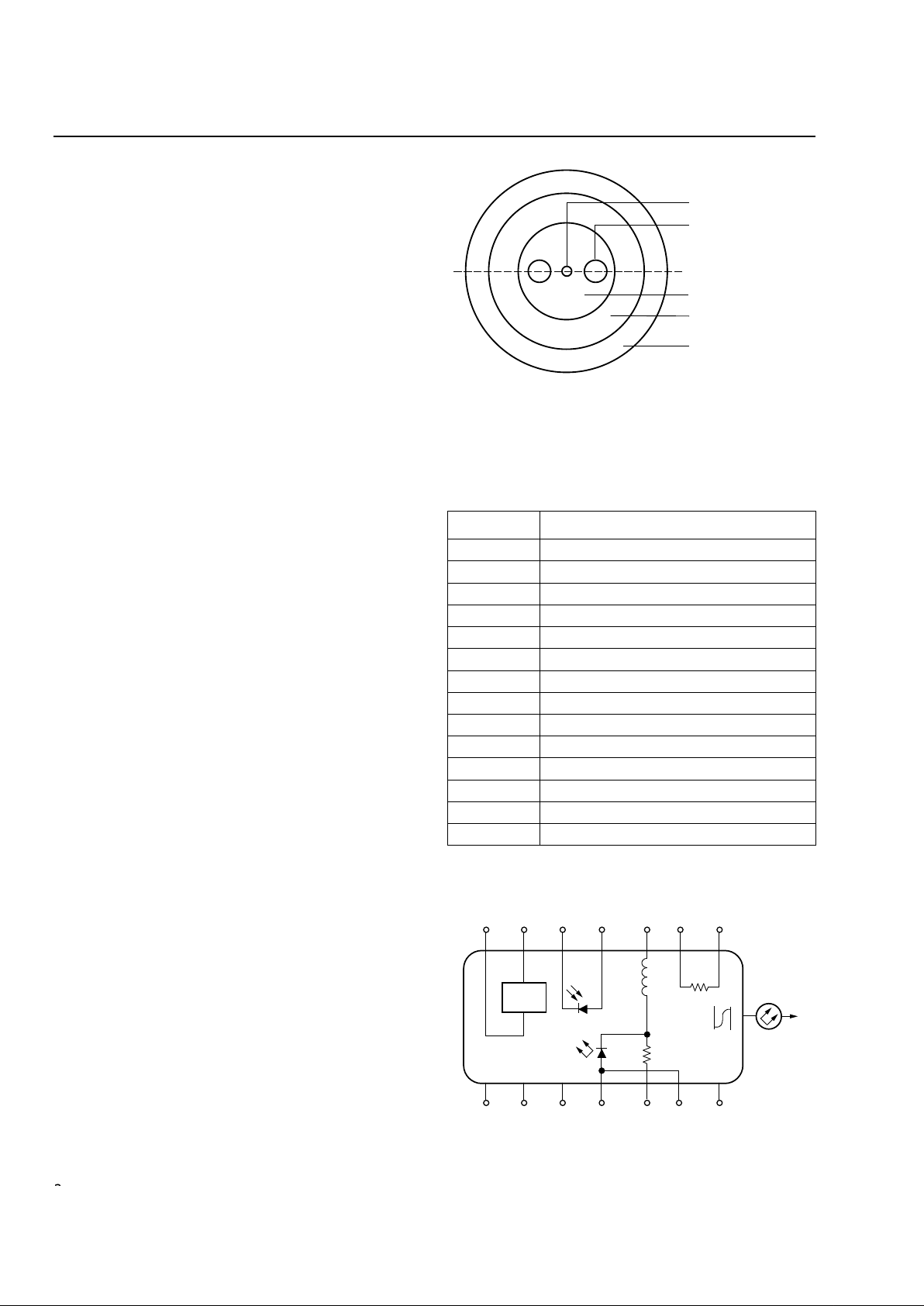
Figure 1. Polarization-Maintaining Fiber
Pin Information
1. A positive current through the thermoelectric heat pump cools the
laser.
2. Both leads should be grounded for optimum performance.
Top view.
Figure 2. Circuit Schematic
Table 1. Pin Descriptions
Pin Name
1 Thermistor
2 Thermistor
3 Laser dc Bias (Cathode) (–)
4 Back-facet Monitor Anode (–)
5 Back-facet Monitor Cathode (+)
6 Thermoelectric Cooler (+)
1
7 Thermoelectric Cooler (–)
1
8 Case Ground
9 Case Ground
10 Case Ground
11 Laser Anode (+)
2
12 RF Laser Input Cathode (–)
13 Laser Anode (+)
2
14 Case Ground
1-771(C).a
CORE
STRESS ROD
PRINCIPAL POLARIZATION
AXIS
CLADDING
INNER COATING
(SILICON & ACRYLATE)
OUTER COATING
(ACRYLATE OR NYLON)
1-567
TEC
L1
160 nH
ISOLATOR
R1
20 Ω
PACKAGE
GROUNDS
–++ – –
+–+
7654 321
8 9 10 11 12 13
TH
10 kΩ
14
Page 3
Data Sheet Wavelength-Selected D2525P
March 2000 Isolated DFB Laser Module with PMF
3
Lucent Technologies Inc.
Absolute Maximum Ratings
Stresses in excess of the absolute maximum ratings can cause permanent damage to the device. These are absolute stress ratings only. Functional operation of the device is not implied at these or any other conditions in excess
of those given in the operations sections of the data sheet. Exposure to absolute maximum ratings for extended
periods can adversely affect device reliability.
* Does not apply to shipping container.
Parameter Symbol Min Max Unit
Laser Reverse Voltage V
RLMAX
—2 V
dc Forward Current I
FLMAX
— 225 mA
Operating Case Temperature Range T
C
–40 70
°
C
Storage Case Temperature Range* T
stg
–40 70
°
C
Photodiode Reverse Voltage V
RPDMAX
—10 V
Photodiode Forward Current I
FPDMAX
—2 mA
Handling Precautions
Power Sequencing
To avoid the possibility of damage to the laser module
from power supply switching transients, follow this
turn-on sequence:
1. All ground connections
2. Most negative supply
3. Most positive supply
4. All remaining connections
Reverse the order for the proper turn-off sequence.
Electrostatic Discharge
CAUTION: This device is susceptible to damage as
a result of electrostatic discharge. Take
proper precautions during both handling and testing. Follow guidelines
such as JEDEC Publication No. 108-A
(Dec. 1988).
Lucent employs a human-body model (HBM) for ESDsusceptibility testing and protection-design evaluation.
ESD voltage thresholds are dependent on the critical
parameters used to define the model. A standard HBM
(resistance = 1.5 k Ω , capacitance = 100 pF) is widely
used and, therefore, can be used for comparison purposes. The HBM ESD threshold presented here was
obtained using these circuit parameters:
Mounting Instructions
The minimum fiber bend radius is 1.50 in.
To avoid degradation in performance, mount the mod-
ule on the board as follows:
1. Place the bottom flange of the module on a flat heat
sink at least 0.5 in. x 1.180 in. (12.7 mm x 30 mm) in
size. The surface finish of the heat sink should be
better than 32 µ in. (0.8 µ m), and the surface flatness
must be better than 0.001 in. (25.4 µ m). Using thermal conductive grease is optional; however, thermal
performance can be improved by up to 5% if conductive grease is applied between the bottom flange and
the heat sink.
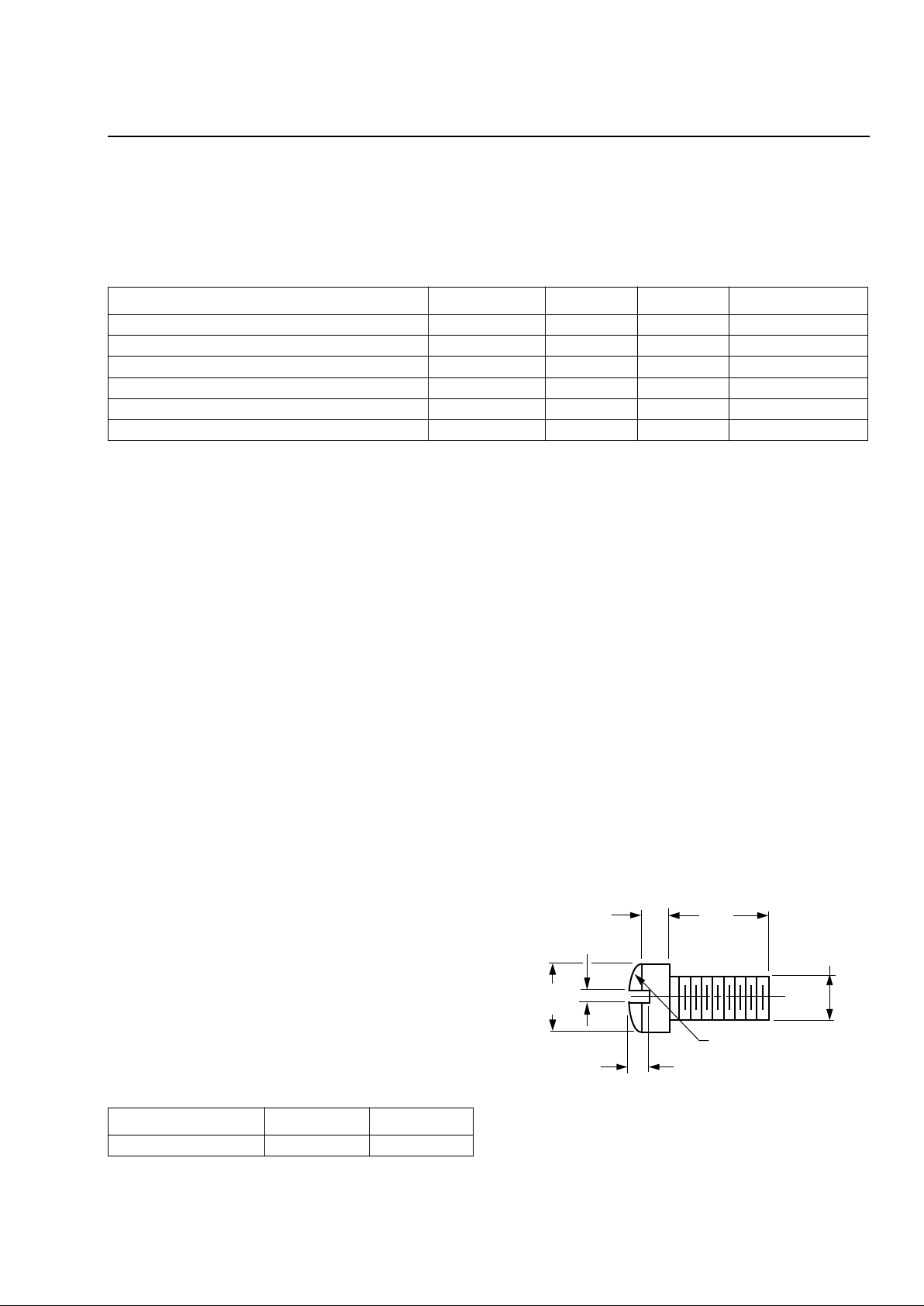
2. Mount four #2-56 screws with Fillister heads
(M2-3 mm) at the four screw hole locations (see Outline Diagram). The Fillister head diameter must not
exceed 0.140 in. (3.55 mm). Do not apply more than
1 in.-lb. of torque to the screws.
Note: Dimensions are in inches and (millimeters).
Figure 3. Fillister Head Screw
Parameter Value Unit
Human-body Model >400 V
0.118
(3.00)
0.062 (1.58)
0.140
(3.56)
0.031 (0.79)
0.129 (3.28) R
0.086
(2.18)
0.041 (1.04)
1-532(C)
Page 4

Wavelength-Selected D2525P Data Sheet
Isolated DFB Laser Module with PMF March 2000
4
Lucent Technologies Inc.
Characteristics
* Standard operating condition is 5.0 V reverse bias.
† Ratio of thermistor resistance at 0 ° C to thermistor resistance at 50 ° C.
* Custom wavelengths available.
† The
ST
ferrule key is not aligned to slow axis of fiber. Connector is intended for testing purposes only.
Table 2. Electrical Characteristics (at 25 ° C laser temperature)
Parameter Symbol Test Conditions Min Typ Max Unit
Threshold Current I
TH
— — 15 40 mA
Drive Current Above Threshold — L
F
= 10 mW — — 110 mA
Laser Forward Voltage V
LF
L
F
= 10 mW (CW) — 1.3 1.8 V
Monitor Reverse-bias Voltage* V
RMON
—3510V
Monitor Current I
RMON
P
O
= 10 mW (CW) 0.200 — — mA
Monitor Dark Current I
D
I
F
= 0, V
RMON
= 5 V — 0.01 0.1
µ
A
Input Impedance Z
IN
— — 25 —
Ω
Thermistor Current I
TC
— 10 — 100
µ
A
Resistance Ratio
†
— — 9.1 9.6 10.1 —
Thermistor Resistance R
TH
T
L
= 25 ° C 9.5 — 10.5 k Ω
TEC Current I
TEC
T
L
= 25 ° C, T
C
= 70 ° C — — 1.0 A
TEC V oltage V
TEC
T
L
= 25 ° C, T
C
= 70 ° C — — 2.0 V
TEC Capacity
∆
TT
C
= 70 ° C50——
°
C
Table 3. Optical Characteristics (at 25 °C laser temperature)
Parameter Symbol Test Conditions Min Typ Max Unit
Peak Optical Output Power PP — 10.0 — — mW
Center Wav elength*
(See Table 4.)
λC TL = 25 °C
CW Wav elength
1529.55 — 1610.06 nm
Line Width (3 dB full width) ∆λ CW, PF = 10.0 mW — 2 10 MHz
Relative Intensity Noise RIN CW, PF = 10.0 mW,
200 MHz < f < 10 GHz
— — –135 dB/Hz
Side-mode Suppression Ratio SMSR CW 33 — — dB
Optical Isolation — TC = 0 °C to 75 °C30——dB
Optical Polarization Extinction
Ratio
†
—0 °C to 75 °C20——dB
Page 5

Data Sheet Wavelength-Selected D2525P
March 2000 Isolated DFB Laser Module with PMF
5
Lucent Technologies Inc.
Outline Diagram
Dimensions are in inches and (millimeters). Tolerances are ±0.005 in. (±0.127 mm).
1-520.g
0.820 (20.83)0.180 (4.56)
0.700 (17.78)
1.180 (29.97)
HEAT SINK
0.215 (5.45)
0.056 (1.42)
0.030 (0.75)
0.575 (14.61)
2.03 (51.6)
39.37 (1000.00)
MIN
0.10
(2.5)
0.260 (6.60)
0.215
(5.47)
REF
0.365
(9.27)
MAX
0.863 (21.91)
0.036
(0.91)
PIN 1
0.078 (1.98)
0.213 (5.40) TYP
0.100 (2.54) TYP
0.105 (2.67) DIA
TYP (4) PLACES
1.025 (26.04)
0.020 (0.51) TYP
0.508 ± 0.008
(12.90 ± 0.2)
STRAIN
RELIEF
PIN 14
0.350
(8.89)
0.500
(12.70)
0.605
(15.37)
MAX
TRADEMARK, CODE, LASER SERIAL NUMBER,
AND DATE CODE IN APPROX. AREA SHOWN
0.200
(5.08)
0.10 ± 0.002
(0.25 ± 0.064)
Page 6

Wavelength-Selected D2525P Data Sheet
Isolated DFB Laser Module with PMF March 2000
6
Lucent Technologies Inc.
High-Power Product
Class IIIb Laser Product
FDA/CDRH Class IIIb laser product. All versions are Class IIIb laser products per CDRH, 21 CFR 1040 Laser
Safety requirements. All versions are Class IIIb laser products per
IEC
* 60825-1:1993. The device has been certi-
fied with the FDA under accession number 8720010.
This product complies with 21 CFR 1040.10 and 1040.11.
8 µm/123 µm—128 µm single-mode fiber with 900 µm loose-tube jacketed fiber and connector
Wavelength = 1.5 µm
Maximum power = 40 mW
Because of size constraints, laser safety labeling is not affixed to the module but attached to the outside of the
shipping carton.
Product is not shipped with power supply.
Caution: Use of controls, adjustments, and procedures other than those specified herein may result in
hazardous laser radiation exposure.
*
IEC
is a registered trademark of The International Electrotechnical Commission.
40 mW 1.5 µm
Page 7

Data Sheet Wavelength-Selected D2525P
March 2000 Isolated DFB Laser Module with PMF
7
Lucent Technologies Inc.
Ordering Information
Table 4. Ordering Information
Device Code Comcode ITU Frequency Wavelength Tolerance
D2525P862 108575085 186.2 1610.06 ±0.4 nm
D2525P863 108575093 186.3 1609.19 ±0.4 nm
D2525P864 108575119 186.4 1608.33 ±0.4 nm
D2525P865 108575127 186.5 1607.47 ±0.4 nm
D2525P866 108575135 186.6 1606.60 ±0.4 nm
D2525P867 108575143 186.7 1605.74 ±0.4 nm
D2525P868 108575150 186.8 1604.88 ±0.4 nm
D2525P869 108575168 186.9 1604.33 ±0.4 nm
D2525P870 108575184 187.0 1603.17 ±0.4 nm
D2525P871 108476227 187.1 1602.31 ±0.4 nm
D2525P872 108476235 187.2 1601.45 ±0.4 nm
D2525P873 108476243 187.3 1600.60 ±0.4 nm
D2525P874 108476250 187.4 1599.75 ±0.4 nm
D2525P875 108476268 187.5 1598.89 ±0.4 nm
D2525P876 108476276 187.6 1598.04 ±0.4 nm
D2525P877 108476284 187.7 1597.19 ±0.4 nm
D2525P878 108476292 187.8 1596.34 ±0.4 nm
D2525P879 108476300 187.9 1595.49 ±0.4 nm
D2525P880 108476318 188.0 1594.64 ±0.4 nm
D2525P881 108476326 188.1 1593.79 ±0.4 nm
D2525P882 108476334 188.2 1592.95 ±0.4 nm
D2525P883 108476342 188.3 1592.10 ±0.4 nm
D2525P884 108476359 188.4 1591.25 ±0.4 nm
D2525P885 108476367 188.5 1590.41 ±0.4 nm
D2525P886 108476375 188.6 1589.57 ±0.4 nm
D2525P887 108476383 188.7 1588.72 ±0.4 nm
D2525P888 108476391 188.8 1587.88 ±0.4 nm
D2525P889 108476409 188.9 1587.04 ±0.4 nm
D2525P890 108476417 189.0 1586.20 ±0.4 nm
D2525P891 108476425 189.1 1585.36 ±0.4 nm
D2525P892 108476433 189.2 1584.53 ±0.4 nm
D2525P893 108476441 189.3 1583.69 ±0.4 nm
D2525P894 108476458 189.4 1582.85 ±0.4 nm
D2525P895 108476516 189.5 1582.02 ±0.4 nm
D2525P896 108476524 189.6 1581.18 ±0.4 nm
D2525P897 108476540 189.7 1580.35 ±0.4 nm
D2525P898 108476557 189.8 1579.52 ±0.4 nm
D2525P899 108476573 189.9 1578.69 ±0.4 nm
Page 8

Wavelength-Selected D2525P Data Sheet
Isolated DFB Laser Module with PMF March 2000
8
Lucent Technologies Inc.
Ordering Information (continued)
Table 4. Ordering Information (continued)
Device Code Comcode ITU Frequency Wavelength Tolerance
D2525P900 108476581 190.0 1577.85 ±0.4 nm
D2525P901 108476599 190.1 1577.02 ±0.4 nm
D2525P902 108476615 190.2 1576.20 ±0.4 nm
D2525P903 108476623 190.3 1575.37 ±0.4 nm
D2525P904 108476631 190.4 1574.54 ±0.4 nm
D2525P905 108476649 190.5 1573.71 ±0.4 nm
D2525P906 108476656 190.6 1572.89 ±0.4 nm
D2525P907 108476664 190.7 1572.06 ±0.4 nm
D2525P908 108476672 190.8 1571.24 ±0.4 nm
D2525P909 108476680 190.9 1570.42 ±0.4 nm
D2525P910 108476698 191.0 1569.59 ±0.4 nm
D2525P911 108476706 191.1 1568.77 ±0.4 nm
D2525P912 108476714 191.2 1567.95 ±0.4 nm
D2525P913 108476722 191.3 1567.13 ±0.4 nm
D2525P914 108476730 191.4 1566.31 ±0.4 nm
D2525P915 108512534 191.5 1565.50 ±0.4 nm
D2525P916 108512542 191.6 1564.68 ±0.4 nm
D2525P17 108196098 191.7 1563.86 ±0.4 nm
D2525P18 108196106 191.8 1563.05 ±0.4 nm
D2525P19 108002452 191.9 1562.23 ±0.4 nm
D2525P20 108002460 192.0 1561.42 ±0.4 nm
D2525P21 108002478 192.1 1560.61 ±0.4 nm
D2525P22 108002486 192.2 1559.79 ±0.4 nm
D2525P23 108002494 192.3 1558.98 ±0.4 nm
D2525P24 108002502 192.4 1558.17 ±0.4 nm
D2525P25 108002510 192.5 1557.36 ±0.4 nm
D2525P26 108002528 192.6 1556.55 ±0.4 nm
D2525P27 108002536 192.7 1555.75 ±0.4 nm
D2525P28 108002544 192.8 1554.94 ±0.4 nm
D2525P29 108002551 192.9 1554.13 ±0.4 nm
D2525P30 108002569 193.0 1553.33 ±0.4 nm
D2525P31 108002577 193.1 1552.52 ±0.4 nm
D2525P32 108002585 193.2 1551.72 ±0.4 nm
D2525P33 108002593 193.3 1550.92 ±0.4 nm
D2525P34 108002601 193.4 1550.12 ±0.4 nm
D2525P35 108003039 193.5 1549.32 ±0.4 nm
D2525P36 108003047 193.6 1548.51 ±0.4 nm
D2525P37 108003054 193.7 1547.72 ±0.4 nm
D2525P38 108003062 193.8 1546.92 ±0.4 nm
D2525P39 108003070 193.9 1546.12 ±0.4 nm
Page 9

Data Sheet Wavelength-Selected D2525P
March 2000 Isolated DFB Laser Module with PMF
9
Lucent Technologies Inc.
Ordering Information (continued)
Table 4. Ordering Information (continued)
Device Code Comcode ITU Frequency Wavelength Tolerance
D2525P40 108003088 194.0 1545.32 ±0.4 nm
D2525P41 108003096 194.1 1544.53 ±0.4 nm
D2525P42 108003104 194.2 1543.73 ±0.4 nm
D2525P43 108003112 194.3 1542.94 ±0.4 nm
D2525P44 108003120 194.4 1542.14 ±0.4 nm
D2525P45 108003138 194.5 1541.35 ±0.4 nm
D2525P46 108003146 194.6 1540.56 ±0.4 nm
D2525P47 108003153 194.7 1539.77 ±0.4 nm
D2525P48 108003161 194.8 1538.98 ±0.4 nm
D2525P49 108003179 194.9 1538.19 ±0.4 nm
D2525P50 108003187 195.0 1537.40 ±0.4 nm
D2525P51 108003195 195.1 1536.61 ±0.4 nm
D2525P52 108003203 195.2 1535.82 ±0.4 nm
D2525P53 108003211 195.3 1535.04 ±0.4 nm
D2525P54 108003229 195.4 1534.25 ±0.4 nm
D2525P55 108003237 195.5 1533.47 ±0.4 nm
D2525P56 108003245 195.6 1532.68 ±0.4 nm
D2525P57 108196114 195.7 1531.90 ±0.4 nm
D2525P58 108196122 195.8 1531.12 ±0.4 nm
D2525P59 108196130 195.9 1530.33 ±0.4 nm
D2525P60 108196148 196.0 1529.55 ±0.4 nm
Page 10

Wavelength-Selected D2525P Data Sheet
Isolated DFB Laser Module with PMF March 2000
For additional information, contact your Microelectronics Group Account Manager or the following:
INTERNET: http://www.lucent.com/micro, or for Optoelectronics information, http://www.lucent.com/micro/opto
E-MAIL: docmaster@micro.lucent.com
N. AMERICA: Microelectronics Group, Lucent Technologies Inc., 555 Union Boulevard, Room 30L-15P-BA, Allentown, PA 18103
1-800-372-2447, FAX 610-712-4106 (In CANADA: 1-800-553-2448, FAX 610-712-4106)
ASIA PACIFIC: Microelectronics Group, Lucent Technologies Singapore Pte. Ltd., 77 Science Park Drive, #03-18 Cintech III, Singapore 118256
Tel. (65) 778 8833, FAX (65) 777 7495
CHINA: Microelectronics Group, Lucent Technologies (China) Co., Ltd., A-F2, 23/F, Zao Fong Universe Building, 1800 Zhong Shan Xi Road,
Shanghai 200233 P. R. China
Tel. (86) 21 6440 0468, ext. 316, FAX (86) 21 6440 0652
JAPAN: Microelectronics Group, Lucent Technologies Japan Ltd., 7-18, Higashi-Gotanda 2-chome, Shinagawa-ku, Tokyo 141, Japan
Tel. (81) 3 5421 1600, FAX (81) 3 5421 1700
EUROPE: Data Requests: MICROELECTRONICS GROUP DATALINE: Tel. (44) 7000 582 368, FAX (44) 1189 328 148
Technical Inquiries: OPTOELECTRONICS MARKETING: (44) 1344 865 900 (Ascot UK)
Lucent Technologies Inc. reserves the right to make changes to the product(s) or information contained herein without notice. No liability is assumed as a result of their use or application. No
rights under any patent accompany the sale of any such product(s) or information.
ST
is a registered trademark of Lucent Technologies Inc.
Copyright © 2000 Lucent Technologies Inc.
All Rights Reserved
March 2000
DS00-073OPTO-1 (Replaces DS00-073OPTO)
 Loading...