

Page 1
Advance Data Sheet
March 1999
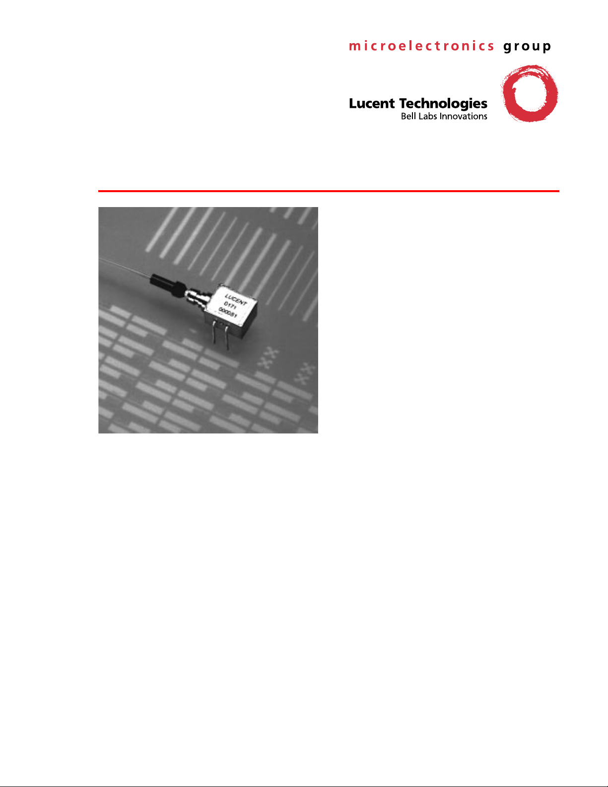
D171-Type
The D171-Type PIN Photodetectors feature a rear-illuminated
planar diode structure with a low-capacitance 4-mil active
area for maximum responsivity and speed.
FastLight
™
PIN Photodetectors
Features
Low-profil e, 4-lead mini-DIL pa ckage
■
— Suitable for SONET applications
High per formance
■
— High speed (<0.5 ns typical rise and fall time)
— High responsivity (0.85 A/W typical)
— Low dark current
Planar st ructure for high reliability
■
Wavelength : 1.1 µm—1.6 µm
■
50 µm core multimode fiber
■
Wide operating temperature range :
■
–40 °C to +85 °C
Wide bandwidth
■
Qualification program : Bellcor e TA-NWT-983
■
Applications
Long-reach SONET OC-3/OC-12 systems and
■
SDH STM-1/STM-4 systems
Secure digital data systems
■
Benefits
Compact si ze
■
Easily board mounted
■
Page 2

D171-Type
FastLight
Advance Data Sheet
PIN Photodetectors March 1999
Description
The D171-Type Photodetector consists of a PIN coupled to a multimode fiber pigail. The device is available
in a 4-pin mini-DIL configuration (see Figure 3 and/or
Table 1) and is ideal for long-reach (SONET) and other
high-speed digital applications.
The D171-Type PIN Photodetector is a rear-illuminated
planar diode structure with a low-capacitance active
area for maximum responsivity and speed.
This device incorporates the new Laser 2000 manufacturing process from the Optoelectronics Products unit
of Lucent Technologies Microelectronics Group. Laser
2000 is a low-cost platform that targets high-volume
manufacturing and tight product distributions on all
optical subassemblies. This platform incorporates an
advanced optical design that is produced on Opto’s
highly automated production lines. The Laser 2000
platform is qualified for central office and uncontrolled
environments, and can be used for applications requiring high perfomance and low cost.
PIN 2
10 V
N
P
LOAD
LN
RN
N
P
RP
Notes:
This equivalent circuit is intended for modeling the package
capacitance. Minimum capacitance is achieved by connecting the Nside to ground, applying a negative voltage to the P-side, and allowing
the package to float (i.e., not connected to ground).
Typical values are as follows:
CO = 0.3 pF to 0.5 pF.
LN, LP = 3.0 nH.
RN, RP = 5 Ω.
CN = 0.4 pF.
CP = 0.1 pF.
CN
CO
CP
LP
PIN 2
PIN 3
LOAD
LOAD
1-697
Figure 2. Equivalent ac Circuit for Digital
Applications
12
RBIAS
PIN 3
Figure 1. Typical Bias Connection
43
1-902.a
Figure 3. D171-Type PIN Photodetector Schematic
(T op View)
Table 1. Pin Descriptions
Pin Number Description
1NC
2 Photodiode Cathode
3 Photodiode Anode
4 Case Ground
22
Lucent Technologies Inc.
Page 3

Advance Data Sheet
March 1999 D171-Type
FastLight
PIN Photodetectors
Absolute Maximum Ratings
Stresses in excess of the absolute maximum ratings can cause permanent damage to the device. These are absolute stress ratings only. Functional operation of the device is not implied at these or any other conditions in excess
of those given in the operational sections of the data sheet. Exposure to absolute maximum ratings for extended
periods can adversely affect device reliability.
Parameter Symbol Min Max Unit
Operating Temperature Range T
Storage Temperature Range T
Forward Voltage V
Reverse Voltage* V
A
stg
F
R
–40 85
–40 90
°
C
°
C
—0V
—30V
Photocurrent — — 4 mA
Humidity — — 95 %
* The recommended reverse bias voltage is 5 V to 15 V.
Handling Precautions
Electrostatic Discharge
CAUTION:This device is susceptible to damage as a result of electrostatic discharge. Take proper
precautions during both handling and testing. Follow guidelines such as JEDEC Publication
No. 108-A (Dec. 1988).
Although protection circuitry is designed into the device, take proper precautions to avoid exposure to ESD.
Electrical Characteristics
TC = 25 °C. Determined with a 50 Ω load.
Parameter Symbol Min Typ Max Unit
Capacitance (f < 900 MHz)* — — 0.65 0.70 pF
Rise/Fall Time tR/t
Dark Current I
Reverse Voltage V
* The minimum capacitance configuration occurs when the N-side of the PIN is grounded and a negative voltage is applied to the P-side, with
the package floating, not grounded (value reference only; not tested in manufacture).
F
D
R
— <0.5 — ns
—1 5nA
2 5 30 V
Optical Characteristics
TC = 25 °C.
Parameter Symbol Min Typ Max Unit
Responsivity R 0.75 0.85 — A/W
Wavelength Range — 1.1 — 1.6
µ
m
Lucent Technologies Inc.
3
Page 4

D171-Type
FastLight
Outline Diagram
Advance Data Sheet
PIN Photodetectors March 1999
Dimensions are in inches and (millimeters)
21
0.250
(6.35)
34
0.310
(7.87)
0.195
(4.95)
.
1.25 MAX
(31.75)
45.28 ± 1.57
(1150 ± 40)
Ø 0.04
(1.02)
FIBER
Ø 0.180
(4.57)
0.012
TYP
(0.30)
+
0.300
(7.62)
SECTION A-A
4
0.114
(2.90)
0.016
(0.41)
0.100
(2.54)
0.100
A
(2.54)
OPTICAL
CONNECTOR
1-933
Lucent Technologies Inc.
Page 5

Advance Data Sheet
March 1999 D171-Type
FastLight
PIN Photodetectors
Qualification Information
The D171-Type PIN Photodetector has completed the following qualification tests and meets the intent of Bellcore
TR-NWT-000468 for interoffice environments and TA-NWT-000983 for outside plant environments.
Table 2. D171-Type PIN Photodetector Qualification Test Plan
Test Conditions Sample Size Reference
Mechanical Shock 500 G 11 MIL-STD-883
Method 2002
Vibration 20 g, 20 Hz—2000 Hz 11 MIL-STD-883
Method 2007
Solderability — 11 MIL-STD-883
Method 2007
Thermal Shock Delta T = 100 °C 11 MIL-STD-883
Method 2003
Fiber Pull 1 kg; 3 times 11 Bellcore 983
Accelerated (biased) Aging 85 °C, 5000 hrs. 25 Bellcore 983
Section 5.18
High-temperature Storage 85 °C, 2000 hrs. 11 Bellcore 983
Temperature Cycling 500 cycles 11 Bellcore 983
Section 5.20
Cyclic Moisture Resistance 10 cycles 11 Bellcore 983
Section 5.23
Damp Heat 40 °C, 95% RH, 1344 hrs. 11 MIL-STD-202
Method 103
Internal Moisture <5000 ppm water vapor 11 MIL-STD-883
Method 1018
Flammability — — TR357
Sec. 4.4.2.5
ESD Threshold — 6 Bellcore 983
Section 5.22
Lucent Technologies Inc.
5
Page 6

Advance Data Sheet
D171-Type
FastLight
PIN Photodetectors March 1999
Ordering Information
Device Code Description Comcode
D171C004BAA PIN 4-Lead Package, 50 µm, MM Fiber, SC Connector 108156654
D171C004BAF PIN 4-Lead Package, 50 µm, MM Fiber, FC Connector 108156662
D171C004CAN PIN 4-Lead Package, SM Fiber, No Connector 108271699
For additional information, contact your Microelectronics Group Account Manager or the following:
INTERNET:
E-MAIL:
N. AMERICA: Microelectronics Group, Lucent Technologies Inc., 555 Union Boulevard, Room 30L-15P-BA, Allentown, PA 18103
ASIA PACIFIC: Microelectronics Group, Lucent Technologies Singapore Pte. Ltd., 77 Science Park Drive, #03-18 Cintech III, Singapore 118256
CHINA: Microelectronics Group, Lucent Technologies (China) Co., Ltd., A-F2, 23/F, Zao Fong Universe Building, 1800 Zhong Shan Xi Road,
JAPAN: Microelectronics Group, Lucent Technologies Japan Ltd., 7-18, Higashi-Gotanda 2-chome, Shinagawa-ku, Tokyo 141, Japan
EUROPE: Data Requests: MICROELECTRONICS GROUP DATALINE:
Lucent Technologies Inc. reserves the right to make changes to the product(s) or information contained herein without notice. No liability is assumed as a result of their use or application. No
rights under any patent accompany the sale of any such product(s) or information.
Copyright © 1999 Lucent Technologies Inc.
All Rights Reserved
March 1999
DS99-166LWP (Replaces DS99-091LWP)
http://www.lucent.com/micro
docmaster@micro.lucent.com
1-800-372-2447
Tel. (65) 778 8833
Shanghai 200233 P. R. China
Tel. (81) 3 5421 1600
Technical Inquiries: OPTOELECTRONICS MARKETING:
, FAX 610-712-4106 (In CANADA:
, FAX (65) 777 7495
, or for Optoelectronics information,
Tel. (86) 21 6440 0468, ext. 316
, FAX (81) 3 5421 1700
1-800-553-2448
FastLight
http://www.lucent.com/micro/opto
, FAX 610-712-4106)
, FAX (86) 21 6440 0652
Tel. (44) 1189 324 299
(44) 1344 865 900
is a trademark of Lucent Technologies Inc.
, FAX (44) 1189 328 148
(Ascot UK)
 Loading...