

Page 1

CXP82400A
CMOS 8-bit Single Chip Microcomputer
Description
The CXP82400A is a CMOS 8-bit single chip microcomputer of piggyback/evaluator combined type,
which is developed for evaluating the function of the
CXP82432A/82440A.
Features
• Wide-range instruction system (213 instructions) to
cover various types of data
—16-bit operation/multiplication and division/Boolean
bit operation instructions
• Minimum instruction cycle 400ns at 10MHz operation
122µs at 32kHz operation
• Applicable EPROM LCC type 27C512 (Maximum 40K bytes are available.)
• Incorporated RAM capacity 1120 bytes (Including fluorescent display data area)
• Peripheral functions
— A/D converter 8-bit, 8-channel, successive approximation method
(Conversion time of 32µs/10MHz)
— Serial interface Incorporated 8-bit, 8-stage FIFO
(Auto transfer for 1 to 8 bytes), 1 channel
8-bit clock sync type, 1 channel
— Timers 8-bit timer
8-bit timer/counter
19-bit time base timer
16-bit capture timer/counter
32kHz timer/counter
— Fluorescent display panel controller/driver
Maximum of 384 segments display possible
1 to 16-digit dynamic display
Dimmer function
High voltage drive output (40V)
On-chip pull-down resistor (Mask option)
Hardware key scan function
(Maximum 16 × 8 key matrix compatible)
— Remote control receiving circuit 8-bit pulse measurement counter with on-chip 6-stage FIFO
— PWM output 14 bits, 1 channel
— CTL duty detection circuit
— High-speed output circuit RTG 4pins
• Interruption 19 factors, 15 vectors, multi-interruption possible
• Standby mode SLEEP/STOP
• Package 100-pin ceramic QFP
Note) Mask option depends on the type of the CXP82400A. Refer to the Products List for details.
100 pin PQFP (Ceramic)
evaluator type
Piggyback/
Structure
Silicon gate CMOS IC
Sony reserves the right to change products and specifications without prior notice. This information does not convey any license by
any implication or otherwise under any patents or other right. Application circuits shown, if any, are typical examples illustrating the
operation of the devices. Sony cannot assume responsibility for any problems arising out of the use of these circuits.
– 1 –
E94Z14-PP
Page 2
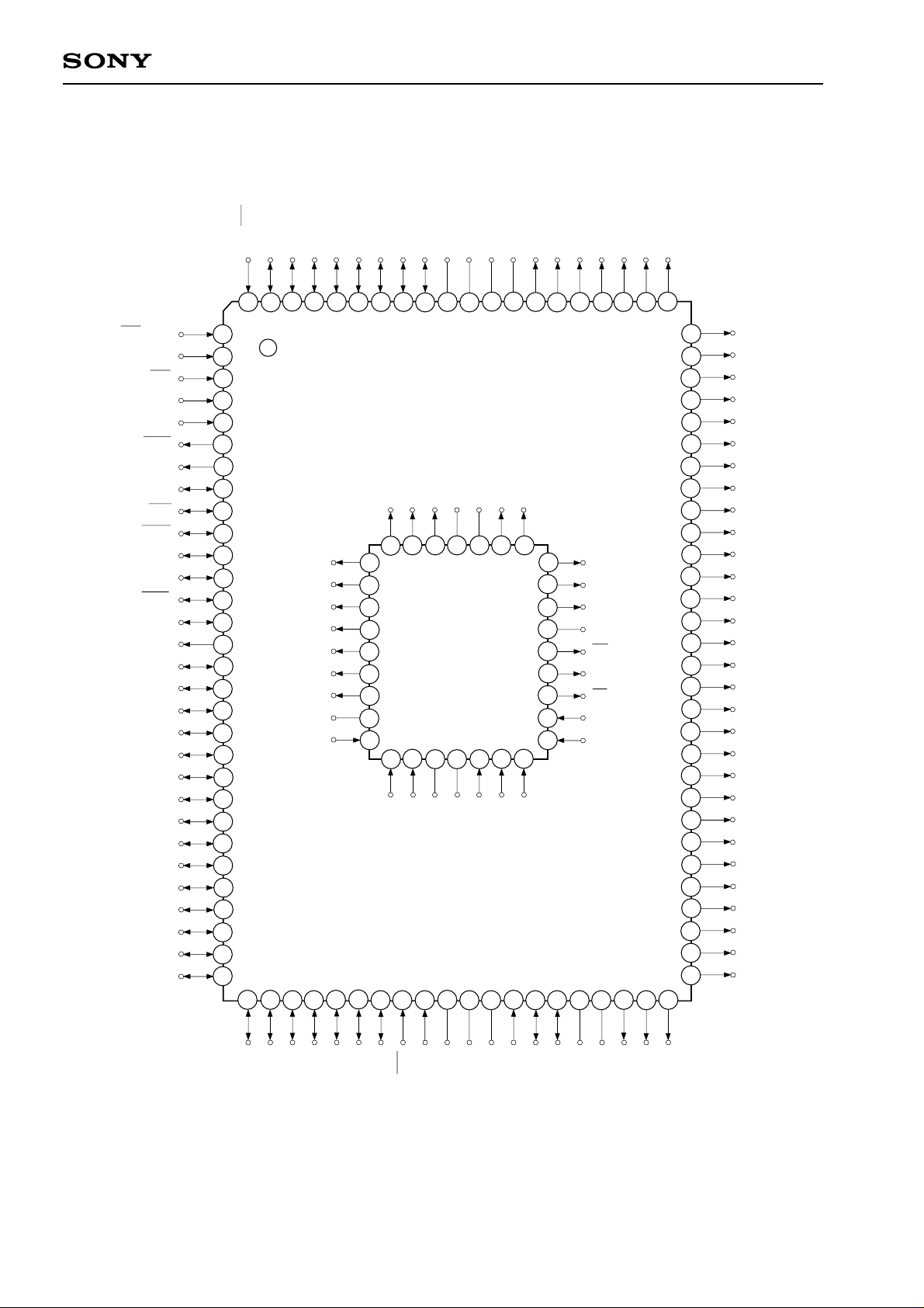
Pin Configuration in Piggyback Mode
PG5
PG6
PG7
PE0/EC0/INT0
PG3/RTO3
PG4
PG0/RTO0
PG1/RTO1
PG2/RTO2
Vss
NC
DD
V
FDP
V
T0
T1
T2
T3
T4
T5
CXP82400A
T6
PE1/EC1/INT1
PE2/INT2
PE3/INT3/NMI
PE4/RMC
PE5/CTL
PE6/PWM
PE7/TO/DD0/ADJ
PB0/CINT
PB1/CS0
PB2/SCK0
PB3/SI0
PB4/SO0
PB5/SCK1
PB6/SI1
PB7/SO1
PC0/KR0
PC1/KR1
PC2/KR2
PC3/KR3
PC4/KR4
PC5/KR5
PC6/KR6
PC7/KR7
PH0
PH1
PH2
PH3
PH4
PH5
PH6
15
16
17
18
19
20
23
28
29
10
11
12
13
14
21
22
25
26
27
30
24
98
97
99
100
1
2
3
4
5
6
7
8
9
32
31
33
34
96
A6
A5
A4
A3
A2
A1
A0
NC
D0
35
95
36
10
12
13
6
11
93
94
92
A15
A12
A7
2
3
4
5
7
8
9
15
16
14
D2
D1
GND
38
39
37
91
40
17
89
88
DD
V
D3
42
31
19
A14
D4
43
87
A13
30
29
28
27
26
25
24
23
22
21
20
D5
44
90
NC
32
1
18
NC
41
86
45
46
85
84
A8
A9
A11
NC
OE
A10
CE
D7
D6
47
48
83
82
49
81
50
78
71
69
68
67
65
64
63
62
80
79
77
76
75
74
73
72
70
66
61
60
59
58
57
56
55
54
53
52
51
T7
T8/S31
T9/S30
T10/S29
T11/S28
T12/S27
T13/S26
T14/S25
T15/S24
PI7/S23
PI6/S22
PI5/S21
PI4/S20
PI3/S19
PI2/S18
PI1/S17
PI0/S16
PF7/S15
PF6/S14
PF5/S13
PF4/S12
PF3/S11
PF2/S10
PF1/S9
PF0/S8
PD7/S7
PD6/S6
PD5/S5
PD4/S4
PD3/S3
TX
Vss
PH7
PA1/AN1
PA0/AN0
PA3/AN3
PA2/AN2
PA5/AN5
PA4/AN4
RST
XTAL
EXTAL
TEX
PA6/AN6
Note) 1. NC (Pin 90) is always connected to VDD.
2. Vss (Pins 41 and 91) are both connected to GND.
– 2 –
REF
AV
PA7/AN7
AVss
PD1/S1
PD0/S0
PD2/S2
Page 3
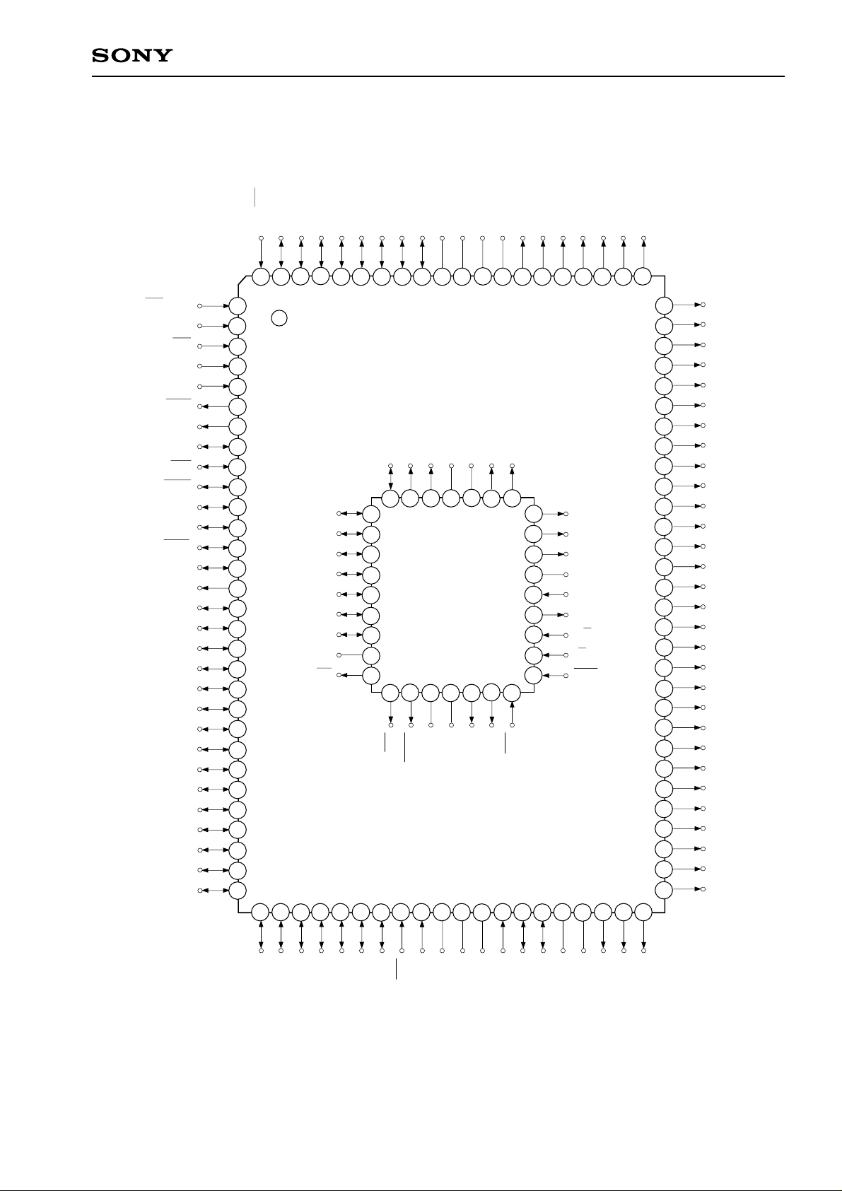
Pin Configuration in Evaluator Mode
PG6
PG7
PE0/EC0/INT0
PG5
PG3/RTO3
PG4
PG0/RTO0
PG1/RTO1
PG2/RTO2
Vss
NC
CXP82400A
FDP
DD
T0
V
V
T1
T2
T3
T4
T5
T6
PE1/EC1/INT1
PE2/INT2
PE3/INT3/NMI
PE4/RMC
PE5/CTL
PE6/PWM
PE7/TO/DD0/ADJ
PB0/CINT
PB1/CS0
PB2/SCK0
PB3/SI0
PB4/SO0
PB5/SCK1
PB6/SI1
PB7/SO1
PC0/KR0
PC1/KR1
PC2/KR2
PC3/KR3
PC4/KR4
PC5/KR5
PC6/KR6
PC7/KR7
PH0
PH1
PH2
PH3
PH4
PH5
PH6
15
16
17
18
19
20
23
28
29
10
11
12
13
14
21
22
25
26
27
30
24
98
97
99
100
1
2
3
4
5
6
7
8
9
32
31
A6/D6
A5/D5
A4/D4
A3/D3
A2/D2
A1/D1
A0/D0
33
34
96
NC
RD
35
95
36
10
12
13
6
11
93
94
92
A12
A7/D7
2
3
4
5
7
8
9
15
16
14
WR
SYNC
38
39
37
91
A15
1
17
GND
40
90
NC
NC
41
32
18
89
DD
V
C2
42
31
19
88
A14
C1
43
30
20
87
A13
RST
44
29
28
27
26
25
23
22
21
24
86
45
46
85
84
A8
A9
A11
NC
HALT
A10
E/P
I/T
MON
47
48
83
82
49
81
50
78
71
69
68
67
65
64
63
62
80
79
77
76
75
74
73
72
70
66
61
60
59
58
57
56
55
54
53
52
51
T7
T8/S31
T9/S30
T10/S29
T11/S28
T12/S27
T13/S26
T14/S25
T15/S24
PI7/S23
PI6/S22
PI5/S21
PI4/S20
PI3/S19
PI2/S18
PI1/S17
PI0/S16
PF7/S15
PF6/S14
PF5/S13
PF4/S12
PF3/S11
PF2/S10
PF1/S9
PF0/S8
PD7/S7
PD6/S6
PD5/S5
PD4/S4
PD3/S3
TX
Vss
PH7
PA1/AN1
PA0/AN0
PA3/AN3
PA2/AN2
PA5/AN5
PA4/AN4
RST
XTAL
EXTAL
TEX
PA6/AN6
Note) 1. NC (Pin 90) is always connected to VDD.
2. Vss (Pins 41 and 91) are both connected to GND.
– 3 –
REF
AV
PA7/AN7
AVss
PD1/S1
PD0/S0
PD2/S2
Page 4

EPROM Read Timing
(Ta = –20 to +75°C, Vcc = 4.5 to 5.5V, Vss = 0V reference)
Item Symbol Pins Min. Max. Unit
CXP82400A
Address → Data
Input delay time
Address → Data
Hold time
A0 to A15
D0 to D7
Products List
tACC
tIH
tACC
A0 to A15
D0 to D7
A0 to A15
D0 to D7
Address data
Input data
120
0
0.8VDD
0.2VDD
tIH
0.8VDD
0.2VDD
ns
ns
Option item
Package
ROM capacitance
Pull-up resistance for reset pin
Pull-down resistance for high
voltage drive pin
Mask type
CXP82432A
CXP82440A
100-pin plastic QFP
32K bytes 40K bytes
Existent/Non-existent
Existent/Non-existent
Products
Piggyback/evaluator type
CXP82400A-U01Q
100-pin ceramic PQFP
EPROM 40K bytes
Existent
Existent: T0 to T15/S24
Non-existent: PD0/S0 to PI7/S23
– 4 –
Page 5

Piggyback mode/evaluator mode can be switched as shown below.
CXP82400A
Piggyback mode Piggyback/evaluator product
LCC type EPROM
Pin 1 marking
Pin 1 index
Package Outline Unit: mm
Evaluator mode
Pin 1 marking
Note)
CPU Probe
Note) Evaluation cap should be connected to
CPU probe.
PIN NO. 1 INDEX
INDEX
24.7
22.3 ± 0.25
100 81
1
6.0
30
31 50
15.58 ± 0.2
18.7
16.3 ± 0.2
4.5
9.48
11.66
100PIN PQFP (CERAMIC)
80
1.27 ± 0.13
12.02
14.22
18.12 ± 0.2
0.3
51
0.7
1.0
1.3 ± 0.3
SONY CODE
EIAJ CODE
JEDEC CODE
81
80
51
50 31
0.45
PQFP-100C-L01
AQFP100-C-0000-A
100
PIN No. 1 INDEX
1
0.65 ± 0.05
0.3 ± 0.08
30
PACKAGE STRUCTURE
PACKAGE MATERIAL
LEAD TREATMENT
LEAD MATERIAL
PACKAGE WEIGHT
CERAMIC
GOLD PLATING
42 ALLOY
5.7g
3.57 ± 0.36
+ 0.05
0.15 – 0.02
10.44 MAX
0.50 ± 0.25
– 5 –
 Loading...