

Page 1
CD Digital Signal Processor
For the availability of this product, please contact the sales office.
Description
The CXD2529Q is a digital signal processor LSI for
CD players and is equipped with built-in digital filters,
zero detection circuit, 1-bit DAC, and analog lowpass filter on a single chip.
Features
Digital Signal Processor (DSP) Block
• Playback mode supporting CAV (Constant Angular
Velocity)
–Frame jitter-free
–Allows 0.5 to double-speed continuous playback
–Allows relative rotational velocity readout
–Supports external spindle control
• Wide capture range mode
–Spindle rotational velocity following method
–Supports normal-speed and double-speed playback
• 16K RAM
• EFM data demodulation
• Enhanced EFM frame sync signal protection
• SEC strategy-based error correction
• Subcode demodulation and Sub Q data error detection
• Digital spindle servo
• 16-bit traverse counter
• Asymmetry compensation circuit
• Serial bus-based CPU interface
• Error correction monitor signals, etc. are output
from a new CPU interface.
• Servo auto sequencer
• Digital audio interface output
• Digital peak meter
CXD2529Q
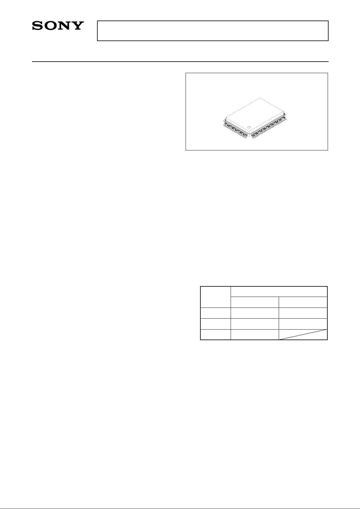
100 pin QFP (Plastic)
Absolute Maximum Ratings
• Supply voltage VDD –0.3 to +7.0 V
• Input voltage VI –0.3 to +7.0 V
(Vss – 0.3V to VDD + 0.3V)
• Output voltage VO –0.3 to +7.0 V
• Storage temperature Tstg –40 to +125 °C
• Supply voltage difference
VSS – AVSS –0.3 to +0.3 V
VDD – AVDD –0.3 to +0.3 V
Note) AVDD includes XVDD, and AVSS includes XVSS.
Recommended Operating Conditions
• Supply voltage VDD 3.4 to 5.25 V
• Operating temperature Topr –20 to +75 °C
Note) The VDD (min.) for the CXD2519Q varies
according to the playback speed selection.
Playback
speed
× 2
CD-DSP block DAC block
VDD (min.) [V]
3.4V 4.5V
Digital Filter, DAC, Analog Low-Pass Filter Block
• DBB (Digital Bass Boost)
• Supports double-speed playback
• Digital de-emphasis
• Digital attenuation function
• Zero detection function
• 8fs oversampling digital filter
• S/N ratio: 100dB or more (master clock: 384fs typ.)
Logical value: 109dB
• THD + N: 0.007% or less (master clock: 384fs typ.)
• Rejection band attenuation: –60dB or more
Applications
CD players
Structure
Silicon gate CMOS IC
Sony reserves the right to change products and specifications without prior notice. This information does not convey any license by
any implication or otherwise under any patents or other right. Application circuits shown, if any, are typical examples illustrating the
operation of the devices. Sony cannot assume responsibility for any problems arising out of the use of these circuits.
– 1 –
× 1
∗1
× 1
∗1
When the internal operation of the CD-DSP
side is set to double-speed mode and the
crystal oscillation frequency is halved,
normal-speed playback results.
Input/Output Capacitances
• Input pin CI 12 (max.) pF
• Output pin CO 12 (max.) pF
Note) Measurement conditions VDD = VI = 0V
3.4V 3.4V
3.4V
fM = 1MHz
E96651A73
Page 2
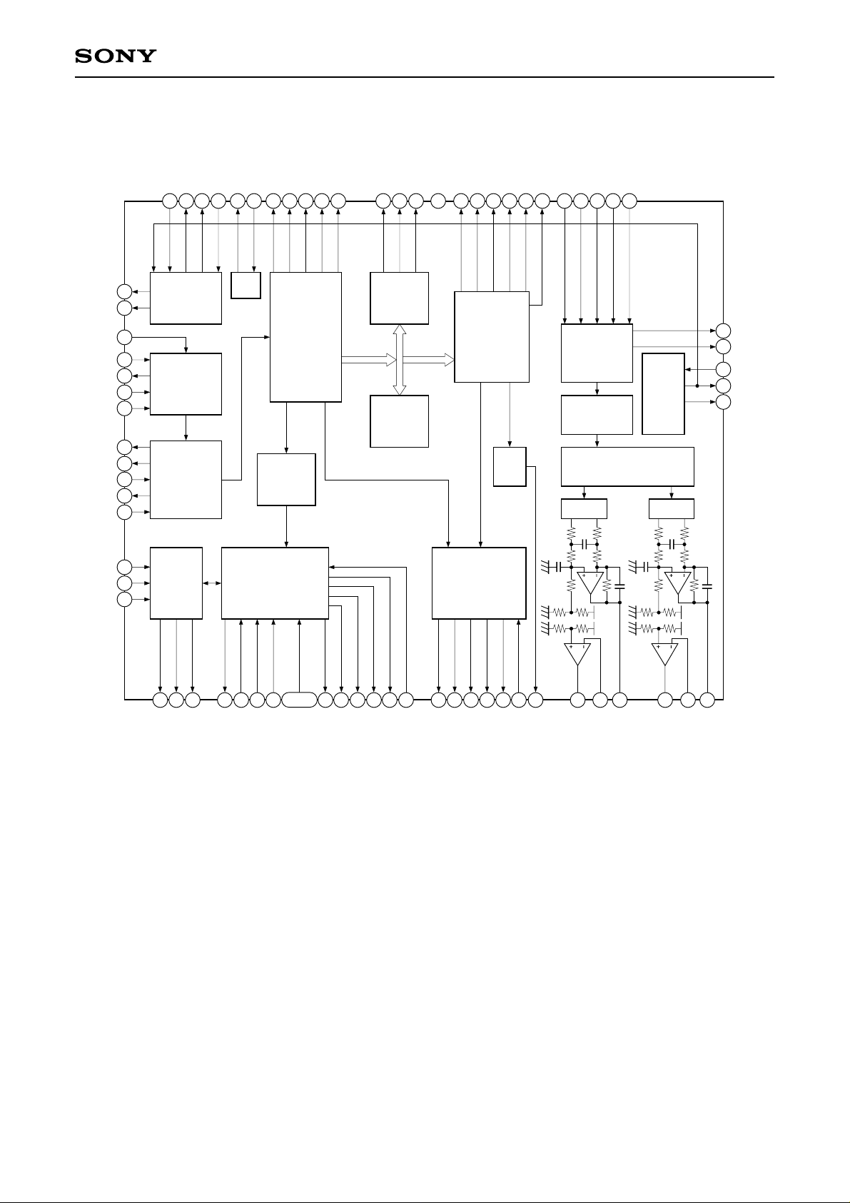
Block Diagram
CXD2529Q
FSTT
C4M
RF
ASYI
ASYO
ASYE
BIAS
XPCK
FILO
FILI
PCO
CLTV
FOK
SEIN
CNIN
VPCO2
VPCO1
XTSL
68
69
70
44
46
47
48
45
60
39
40
38
42
23
13
14
Clock
Generator
Asymmetry
Corrector
Digital
PLL
Servo
Auto
Sequencer
VCKI
35
33
34
36
OSC
V16M
37
GTOP
VCTL
58
Sub Code
Processor
CPU
Interface
demodurator
59
XUGF
61
EFM
GFS
EMPH
72
WFCK
74
MNT1
MNT3
65
66
Error
Corrector
16K
RAM
67
MNT0
31
TES0
62
RFCK
63
Interface
Digital
CLV
C2PO
49
D/A
LRCK
WDCK
50
Digital
OUT
PCMD
52
BCK
54
EMPHI
73
Over Sampling
BCKI
PCMDI
LRCKI
51
Serial-In
Interface
Digital Filter
PWM PWM
55
53
80
3rd-Order
Noise Shaper
SYSM
Timing
Logic
89
90
4
3
6
RMUT
LMUT
XTAI
XTAO
CKOUT
15
16
DATO
17
XLTO
CLKO
9
SENS
10
11
DATA
12
XLAT
18 to 21
CLOK
22
XLON
SPOA to D
75
76
SCOR
77
SBSO
8
EXCK
7
SQSO
SQCK
26
27 28
MON
MDP
29
MDS
64
LOCK
30
XROF
71
PWMI
DOUT
93
LOUT2
94
AIN2
95
AOUT2
86
LOUT1
85
AIN1
84
AOUT1
– 2 –
Page 3

Pin Configuration
SYSM
80
79
81
NC
82
SS
AV
83
AVDD
AIN1
LOUT1
AV
XV
XTAI
XTAO
XV
AVSS
LOUT2
AIN2
AV
AVSS
NC
NC
XRST
84
85
86
87
SS
88
DD
89
90
91
SS
92
93
94
95
96
DD
97
98
99
100
1
2
DD
V
AOUT1
AOUT2
CXD2529Q
SS
DD
V
V
78
77
4
3
SS
V
LMUT
SBSO
EXCK
76
5
TES2
RMUT
SCOR
75
6
CKOUT
74
WFCK
7
SQCK
EMPHI
73
8
SQSO
72
9
EMPH
DOUT
71
10
SENS
DATA
70
11
C4M
69
12
XLAT
FSTT
68
13
CLOK
XTSL
67
14
SEIN
MNT0
66
15
CNIN
MNT1
65
16
DATO
MNT3
64
17
XLTO
XROF
63
18
CLKO
C2PO
62
19
SPOA
RFCK
61
20
SPOB
GFS
XPCK
60
21
SPOC
SPOD
59
22
XUGF
58
23
XLON
DD
V
GTOP
57
24
DD
V
FOK
SS
V
55
56
26 27 28
25
SS
V
BCKI
54
MON
BCK
53
MDP
PCMD
PCMDI
52
29
MDS
LOCK
51
30
LRCKI
50
49
48
47
46
45
44
43
42
41
40
39
38
37
36
35
34
33
32
31
PWMI
LRCK
WDCK
ASYE
ASYO
ASYI
BIAS
RF
DD
AV
CLTV
SS
AV
FILI
FILO
PCO
VCTL
V16M
VCKI
VPCO1
VPCO2
TES1
TES0
– 3 –
Page 4
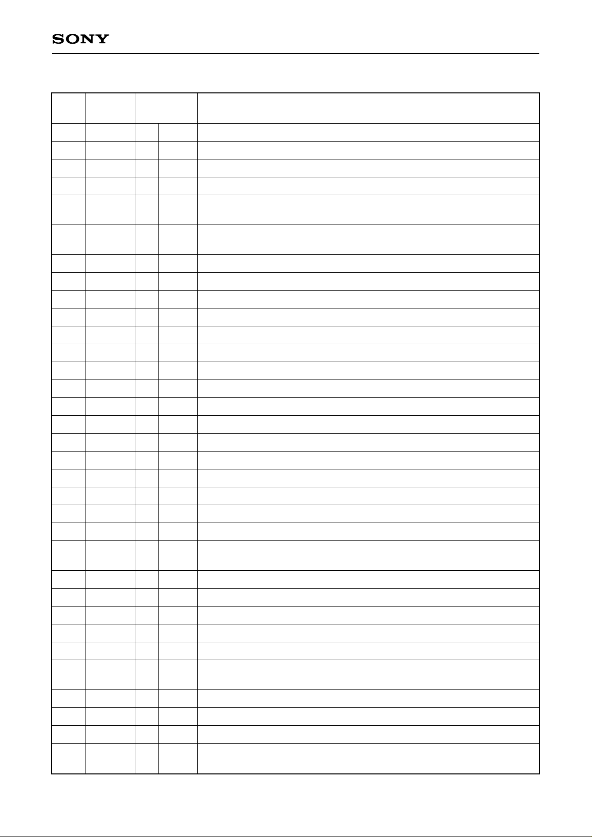
Pin Description
CXD2529Q
Pin
No.
1
2
3
4
5
6
7
8
9
10
11
12
13
14
Symbol I/O Description
VDD
VSS
LMUT
RMUT
TES2
CKOUT
SQCK
SQSO
SENS
DATA
XLAT
CLOK
SEIN
CNIN
—
—
O
O
O
O
O
O
—
—
1, 0
1, 0
1, 0
1, 0
I
1, 0
1, 0
I
I
I
I
I
Power supply (+5V).
GND.
Left-channel zero detection flag.
Right-channel zero detection flag.
TEST output pin; normally open.
Master clock frequency-divider output. Selects and outputs XTAI × 1, × 1/2,
× 1/4 or low only.
SQSO readout clock input.
Sub Q 80-bit serial output.
SENS output to CPU.
Serial data input from CPU.
Latch input from CPU. Serial data is latched at the falling edge.
Serial data transfer clock input from CPU.
SENS input from SSP.
Track jump count signal input.
15
16
17
18
19
20
21
22
23
24
25
26
27
28
29
DATO
XLTO
CLKO
SPOA
SPOB
SPOC
SPOD
XLON
FOK
VDD
VSS
MON
MDP
MDS
LOCK
O
O
O
O
—
—
O
O
O
O
I
I
I
I
I
1, 0
1, 0
1, 0
1, 0
—
—
1, 0
1, Z, 0
1, Z, 0
1, 0
Serial data output to SSP.
Serial data latch output to SSP. Latched at the falling edge.
Serial data transfer clock output to SSP.
Microcomputer extended interface (input A).
Microcomputer extended interface (input B).
Microcomputer extended interface (input C).
Microcomputer extended interface (input D).
Microcomputer extended interface (output).
Focus OK input.
Used for SENS output and the servo auto sequencer.
Power supply (+5V).
GND.
Spindle motor on/off control output.
Spindle motor servo control.
Spindle motor servo control.
GFS is sampled at 460Hz; when GFS is high, this pin outputs a high signal.
If GFS is low eight consecutive samples, this pin outputs low.
30
31
32
33
PWMI
TES0
TES1
VPCO2
I
I
I
1, Z, 0
O
Spindle motor external control input.
TEST pin; normally GND.
TEST pin; normally GND.
Wide-band EFM PLL charge pump output. Turned on/off by FCSW of
address E.
– 4 –
Page 5

CXD2529Q
Pin
No.
34
35
36
37
38
39
40
41
42
43
44
45
46
47
48
Symbol I/O Description
VPCO1
VCKI
V16M
VCTL
PCO
FILO
FILI
AVSS
CLTV
AVDD
RF
BIAS
ASYI
ASYO
ASYE
O
O
O
O
—
—
O
1, Z, 0
I
1, 0
I
1, Z, 0
Analog
I
—
I
—
I
I
I
1, 0
I
Charge pump output for wide-band EFM PLL.
VCO2 oscillation input for the wide-band EFM PLL.
VCO2 oscillation output for the wide-band EFM PLL.
VCO2 control voltage input for the wide-band EFM PLL.
Master PLL charge pump output.
Master PLL (slave = digital PLL) filter output.
Master PLL filter input.
Analog GND.
Master VCO control voltage input.
Analog power supply (+5V).
EFM signal input.
Constant current input of the asymmetry circuit.
Asymmetry comparator voltage input.
EFM full-swing output (low = VSS, high = VDD).
Low: asymmetry circuit off; high: asymmetry circuit on
49
50
51
52
53
54
55
56
57
58
59
60
61
62
63
64
65
WDCK
LRCK
LRCKI
PCMD
PCMDI
BCK
BCKI
VSS
VDD
GTOP
XUGF
XPCK
GFS
RFCK
C2PO
XROF
MNT3
O
O
O
O
—
—
O
O
O
O
O
O
O
O
1, 0
1, 0
I
1, 0
I
1, 0
I
—
—
1, 0
1, 0
1, 0
1, 0
1, 0
1, 0
1, 0
1, 0
D/A interface. Word clock f = 2fs
D/A interface. LR clock output f = fs
LR clock input.
D/A interface. Serial data output (two’s complement, MSB first).
D/A interface. Serial data input (two’s complement, MSB first).
D/A interface. Bit clock output.
D/A interface. Bit clock input.
GND.
Power supply (+5V).
GTOP output.
XUGF output.
XPLCK output.
GFS output.
RFCK output.
C2PO output.
XRAOF output.
MNT3 output.
66
67
68
69
MNT1
MNT0
XTSL
FSTT
1, 0
O
1, 0
O
I
1, 0
O
MNT1 output.
MNT0 output.
Crystal selector input. Low: 16.9344MHz; high: 33.8688MHz.
2/3 frequency-divider output for Pins 89 and 90.
– 5 –
Page 6
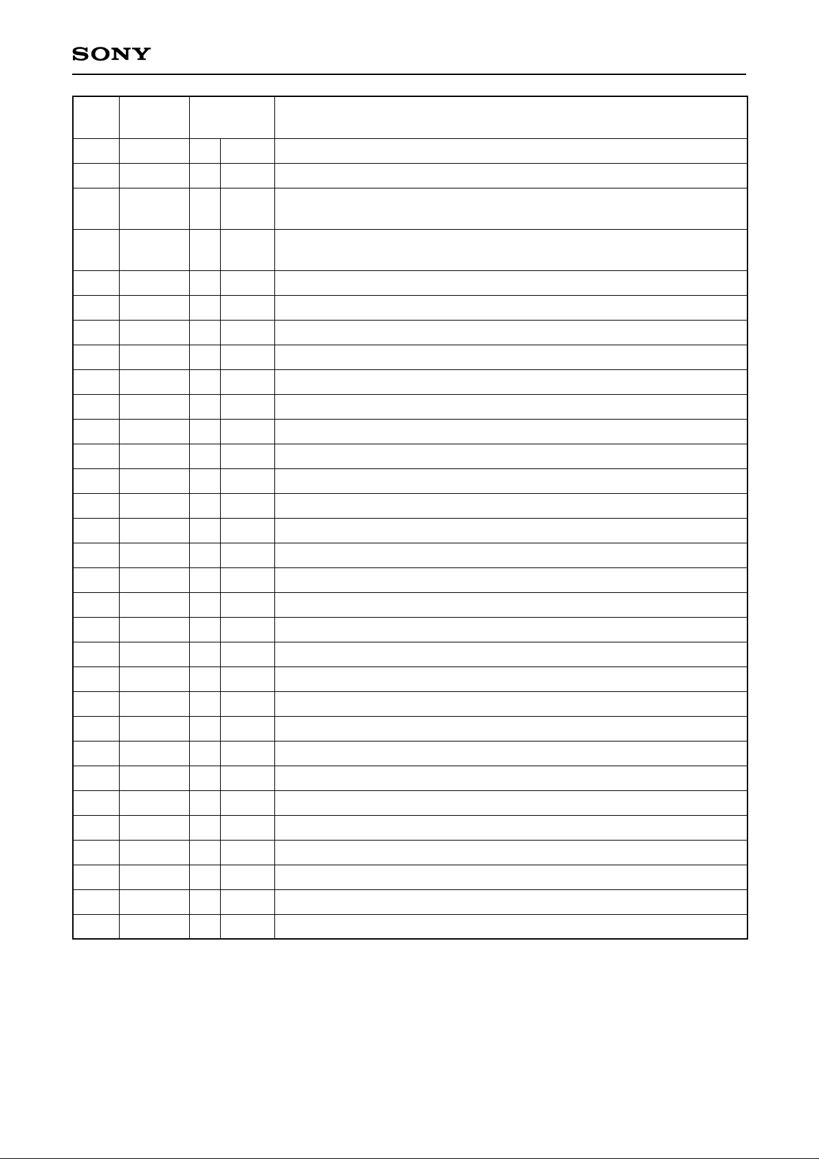
CXD2529Q
Pin
No.
70
71
72
73
74
75
76
77
78
79
80
81
82
83
Symbol I/O Description
C4M
DOUT
EMPH
EMPHI
WFCK
SCOR
SBSO
EXCK
VSS
VDD
SYSM
O
O
O
O
O
O
—
—
1, 0
1, 0
1, 0
I
1, 0
1, 0
1, 0
I
—
—
I
4.2336MHz output. 1/4 frequency-divided VCKI output in CAV-W mode.
Digital Out output.
Outputs a high signal when the playback disc has emphasis, and a low
signal when there is no emphasis.
Inputs a high signal when de-emphasis is on, and a low signal when de-
emphasis is off.
WFCK output.
Outputs a high signal when either subcode sync S0 or S1 is detected.
Sub P to W serial output.
SBSO readout clock input.
GND.
Power supply (+5V).
Mute input. Active when high.
NC
AVSS
AVDD
—
—
—
—
Analog GND.
Analog power supply (+5V).
84
85
86
87
88
89
90
91
92
93
94
95
96
97
98
99
100
AOUT1
AIN1
LOUT1
AVSS
XVDD
XTAI
XTAO
XVSS
AVSS
LOUT2
AIN2
AOUT2
AVDD
AVSS
NC
NC
XRST
O
O
—
O
—
O
O
—
—
Left-channel analog output.
I
Left-channel operational amplifier input.
Left-channel LINE output.
—
Analog GND.
Power supply for master clock.
I
Crystal oscillation circuit input. Input the external master clock via this pin.
Crystal oscillation circuit output.
GND for master clock.
—
Analog GND.
Right-channel LINE output.
I
Right-channel operational amplifier input.
Right-channel analog output.
—
—
I
Analog power supply (+5V).
Analog GND.
System reset. Reset when low.
Notes) • PCMD is an MSB first, two’s complement output.
• GTOP is used to monitor the frame sync protection status. (High: sync protection window released.)
• XUGF is the negative pulse for the frame sync derived from the EFM signal. It is the signal before
sync protection.
• XPLCK is the inverse of the EFM PLL clock. The PLL is designed so that the falling edge of XPLCK
and the EFM signal transition point coincide.
• GFS goes high when the frame sync and the insertion protection timing match.
• RFCK is derived with the crystal accuracy. This signal has a cycle of 136µs (during normal-speed).
• C2PO represents the data error status.
• XRAOF is generated when the 16K RAM exceeds the ±4F jitter margin.
– 6 –
Page 7
CXD2529Q
Electrical Characteristics
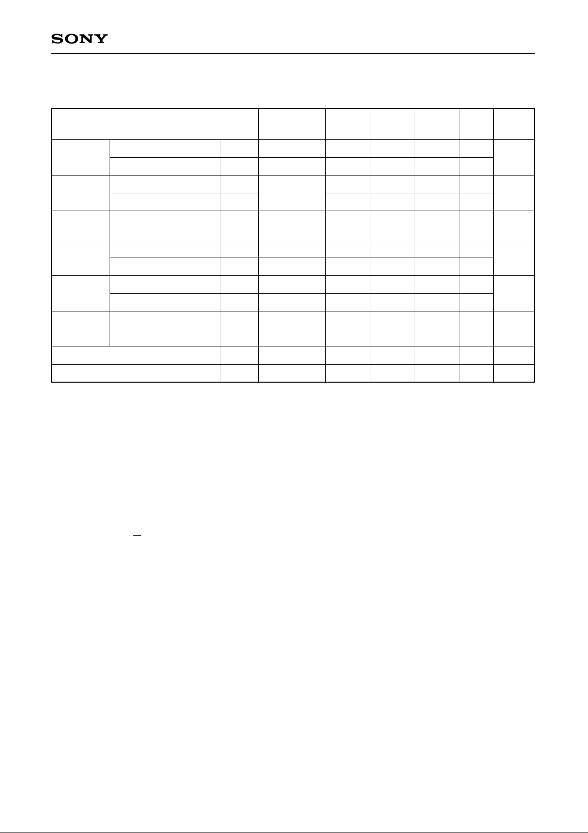
DC Characteristics (VDD = AVDD = 5.0V ± 5%, VSS = AVSS = 0V, Topr = –20 to +75°C)
∗
Item
Input
voltage (1)
Input
voltage (2)
Input
voltage (3)
Output
voltage (1)
Output
voltage (2)
Output
voltage (4)
High level input voltage
Low level input voltage
High level input voltage
Low level input voltage
Input voltage
High level output voltage
Low level output voltage
High level output voltage
Low level output voltage
High level output voltage
Low level output voltage
Input leak current
Tri-state pin output leak current
VIH (1)
VIL (1)
VIH (2)
VIL (2)
VIN (3)
VOH (1)
VOL (1)
VOH (2)
VOL (2)
VOH (4)
VOL (4)
ILI
ILO
Conditions Min. Typ. Max. Unit
0.7VDD
0.3VDD
0.8VDD
Schmitt input
0.2VDD
Analog input
IOH = –1mA
IOL = 1mA
IOH = –1mA
IOL = 2mA
IOH = –0.28mA
IOL = 0.36mA
VI = 0 to 5.50V
VO = 0 to 5.50V
Vss
VDD – 0.5
0
VDD – 0.5
0
VDD – 0.5
0
–5
–5
VDD
VDD
0.4
VDD
0.4
VDD
0.4
5
5
V
V
V
V
V
V
V
V
V
V
V
µA
µA
Applicable
pins
∗1
∗2
∗3
∗4
∗5
∗6
∗1, ∗2, ∗3
∗7
Applicable pins
∗1
XTSL, DATA, XLAT, PWMI, SYSM, EMPHI, PCMDI
∗2
CLOK, XRST, EXCK, SQCK, FOK, SEIN, CNIN, VCKI, ASYE, LRCKI, BCKI, SPOA to D
∗3
CLTV, FILI, RF, VCTL, AIN1, AIN2
∗4
MDP, PCO, VPCO1, VPCO2
∗5
ASYO, DOUT, FSTT, C4M, SBSO, SQSO, SCOR, EMPH, MON, LOCK, WDCK, DATO, CLKO, XLTO,
SENS, MDS, MNT0 to 3, WFCK, V16M, CKOUT, LMUT, RMUT, XLON, LRCK, PCMD, BCK, GTOP,
XUGF, XPCK, GFS, RFCK, C2PO, XRAOF
∗6
FILO
∗7
MDS, MDP, PCO, VPCO1, VPCO2
∗
note) : XVDD and XVSS are included for AVDD and AVSS, respectively.
Those are the same for the explanation from the next page.
– 7 –
Page 8
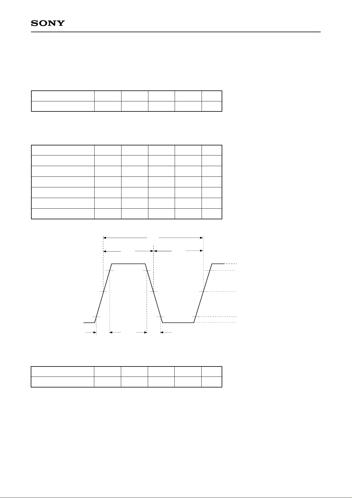
AC Characteristics
1. XTAI pin
(1) When using self-excited oscillation
(Topr = –20 to +75°C, VDD = AVDD = 5.0V ± 5%)
Item Symbol Min. Typ. Max Unit
Oscillation frequency fMAX 15 34 MHz
(2) When inputting pulses to XTAI
(Topr = –20 to +75°C, VDD = AVDD = 5.0V ± 5%)
Item Symbol Min. Typ. Max Unit
CXD2529Q
High level pulse width
Low level pulse width
Pulse cycle
Input high level
Input low level
Rise time, fall time
XTAI
tWHX
tWLX
tCK
VIHX
13
13
26
VDD – 1.0
VILX
tR, tF
tWHX
tR tF
tCK
tWLX
500
500
1,000
0.8
10
ns
ns
ns
V
V
ns
IHX
V
V
IHX × 0.9
VDD/2
VIHX × 0.1
VILX
(3) When inputting sine waves to XTAI via a capacitor
(Topr = –20 to +75°C, VDD = AVDD = 5.0V ± 5%)
Item Symbol Min. Typ. Max Unit
Input amplitude V1 2.0 VDD + 0.3 Vp-p
– 8 –
Page 9

CXD2529Q
2. CLOK, DATA, XLAT, CNIN, SQCK and EXCK pins (VDD = AVDD = 5.0V ± 5%, VSS = AVSS = 0V, Topr = –20 to +75°C)
Item Symbol Min. Typ. Max. Unit
Clock frequency
Clock pulse width
Setup time
Hold time
Delay time
Latch pulse width
EXCK SQCK frequency
EXCK SQCK pulse width
CLOK
DATA
XLAT
EXCK
CNIN
SQCK
SQSO
SBSO
fCK
tWCK
tSU
tH
tD
tWL
fT
fWT
tSU
tSU
750
300
300
300
750
∗
750
1/fCK
tWCK tWCK
tH
tWT tWT
1/fT
tH
0.65
MHz
ns
ns
ns
ns
ns
∗
0.65
MHz
ns
tD
tWL
∗
In pseudo double-speed playback mode, except when SQSO is Sub Q Read, the maximum operating
frequency for SQCK is 300kHz and the minimum pulse width is 1.5µs.
3. BCKI, LRCKI, PCMDI pins (VDD = AVDD = 5.0V ± 5%, VSS = AVSS = 0V, Topr = –20 to +75°C)
Item Symbol Conditions Typ.
BCK pulse width
DATAL, R setup time
DATAL, R hold time
LRCK setup time
BCKI
PCMDI
tW
tSU
tH
tSU
VDD/2 VDD/2
tSU
(PCMDI)
Min. Max. Unit
94
18
18
18
tW (BCKI) tW (BCKI)
H
t
(PCMDI)
tSU
(LRCKI)
ns
ns
ns
ns
LRCKI
– 9 –
Page 10
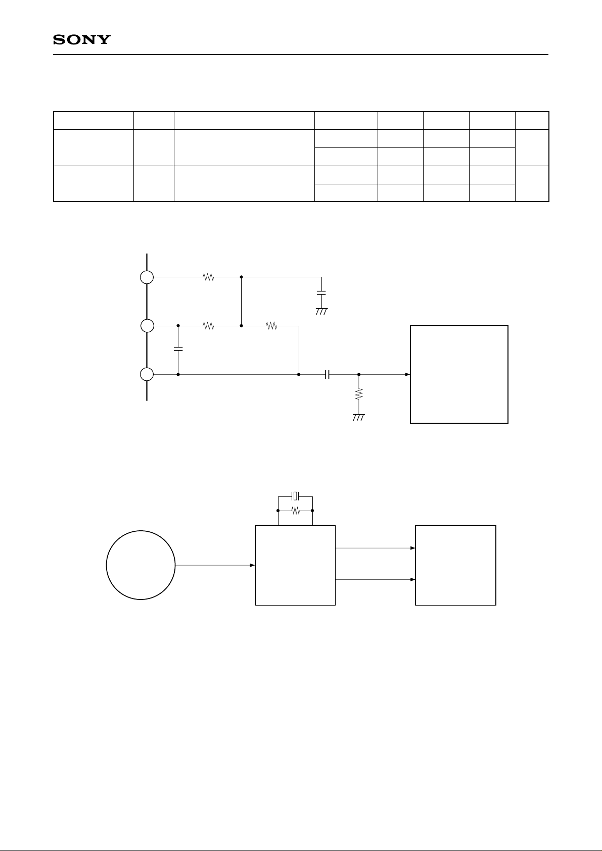
1-bit DAC, LPF Block Analog Characteristics
Analog Characteristics (VDD = AVDD = 5.0V, VSS = AVSS = 0V, Ta = 25°C)
CXD2529Q
Item
Total harmonic
distortion
S/N ratio
Symbol
THD
S/N
Conditions
1kHz, 0dB data
1kHz, 0dB data
(using A-weighting filter)
Crystal
384Fs
768Fs
384Fs
768Fs
Min. Typ. Max. Unit
0.0050
0.0045
96
96
For both items, Fs = 44.1kHz.
The circuits for measuring the total harmonic distortion and S/N ratio are shown below.
150p
12k
12k
12k
680p
SHIBASOKU (AM51A)
22µ
100k
AOUT1 (2)
AIN1 (2)
LOUT1 (2)
0.0070
%
0.0065
100
dB
100
Audio Analyzer
TEST DISC
LPF External Circuit Diagram
768Fs/384Fs
Rch A
DATA RF
CXD2529Q
Lch B
Block Diagram for Measuring Analog Characteristics
Audio Analyzer
– 10 –
Page 11

(VDD = AVDD = 5.0V, VSS = AVSS = 0V, Topr = –20 to +75°C)
CXD2529Q
Item Symbol
Output voltage
Load resistance
∗
When the sine wave of 1kHz and 0dB is output and it is measured using the circuit shown on the previous
VOUT
RL
Min.
8
Typ.
1.23
Max.
∗
Vrms
kΩ
Applicable pinsUnit
∗1
∗1
page.
Applicable pins
∗1
LOUT1, LOUT2
– 11 –
Page 12
Description of Functions
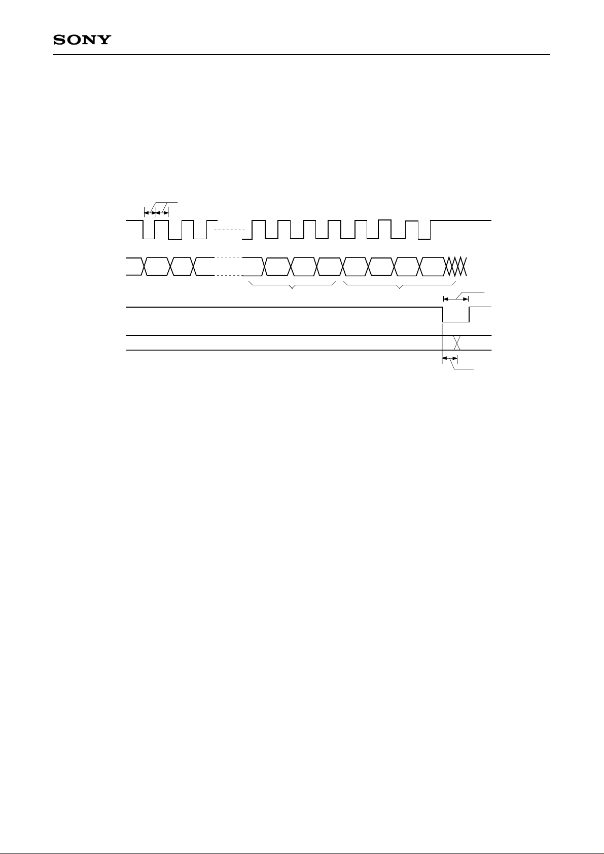
1. CPU Interface and Instructions
• CPU Interface
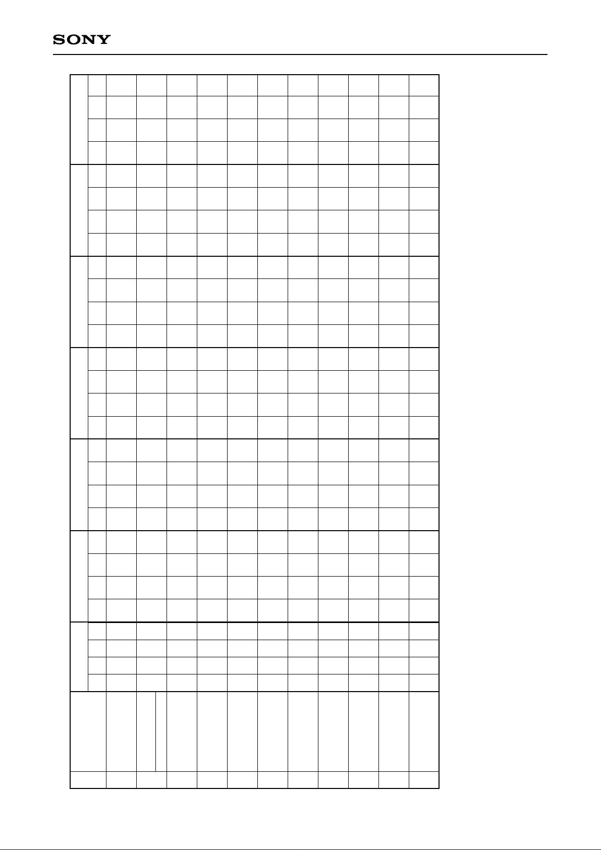
This interface uses DATA, CLOK and XLAT to set the modes.
The interface timing chart is shown below.
750ns or more
CLOK
CXD2529Q
DATA
XLAT
Registers 4toE
D1
D2 D3 D0 D1 D2 D3
Data
Address
750ns or more
Valid
300ns max
• Information on each address and the data is provided in Table 1-1.
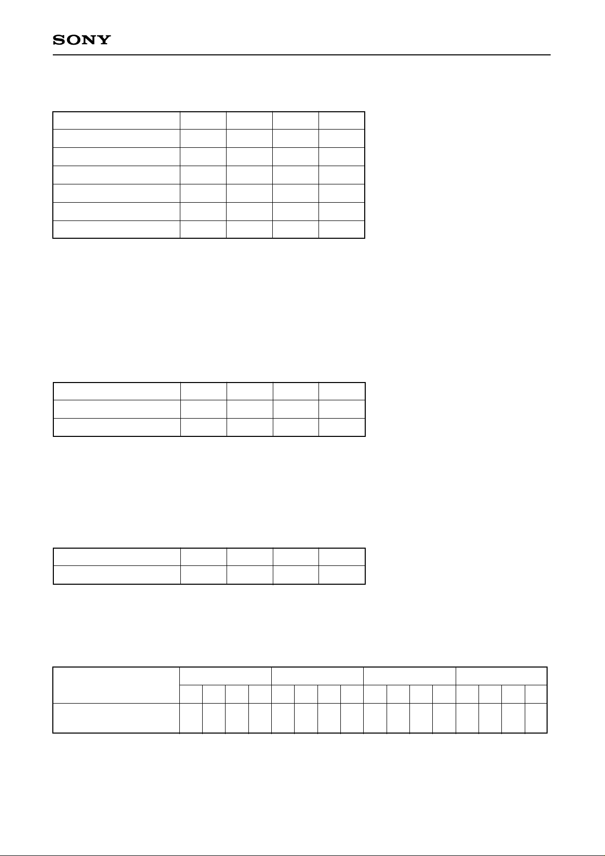
• The internal registers are initialized by a reset when XRST is low; the initialization data is shown in Table 1-2.
Note) When XLAT is low, SQCK must be set high.
– 12 –
Page 13

CXD2529Q
D1 D0
Data 6
D3 D2
D1 D0
Data 5
D3 D2
D0
Data 4
D3 D2 D1
D0
Data 3
D3 D2 D1
Data 2
D3 D2 D1 D0
Data 1
D2 D1 D0
D3
D0
D1
Address
D3 D2
—
—
—
—
—
—
—
—
—
—
—
—
—
—
—
—
—
—
—
—
AS0
AS1
AS2
AS3
0
0
1
0
—
—
—
—
—
—
—
—
—
—
—
—
—
—
—
—
—
—
—
—
0.02ms
0.05ms
0.05ms
0.09ms
0.09ms
0.18ms
0.18ms
0.36ms
1
0
1
0
—
—
—
—
—
—
—
—
—
—
—
—
—
—
—
—
—
—
—
—
1.45ms
2.9ms
5.8ms
11.6ms
0
1
1
0
—
—
—
—
—
—
—
—
1
2
4
8
16
32
64
128
256
512
1024
2048
4096
8192
16384
32768
1
1
1
0
—
—
—
—
—
—
—
—
0
1
0
0
KSL0
KSL1
KSL2
KSL3
VCO
SEL2
SOCT
0
VCO
SEL1
WSEL
DOUT
ON/OFF
Mute
DOUT
CDROM
0
0
0
1
—
—
—
—
—
—
—
—
0
—
0
—
—
DCOF
0
—
0
—
0
—
ZMUT
ZMUT
ZDPL
ZDPL
CKOSL0
CKOSL0
CKOSL1
CKOSL1
MCSL
MCSL
OPSL10OPSL1
SYCOF
0
0
0
0
0
DSPB
ON/OFF
0
1
0
0
1
1
SYCOF
0
0
0
0
0
DSPB
ON/OFF
0
1
0
0
1
—
BBSL
—
BSBST
—
LRWO
—
FMUT
AD0
AD0
AD1
AD1
AD2
AD2
AD3
AD3
AD4
AD4
AD5
AD5
AD6
AD6
AD7
AD7
AD8
AD8
AD9
AD9
0
0
SMUT
SMUT
EMPH
EMPH
OPSL20OPSL2
0
0
ATT
Mute
0
0
0
1
0
1
1
0
0
ATT
Mute
0
0
0
1
0
1
—
—
—
—
—
—
—
—
—
—
—
—
—
—
—
—
—
—
—
—
0
CPUSR
SL0
SL1
1
1
0
1
—
—
—
—
—
—
—
—
—
—
—
—
—
—
—
—
—
—
—
—
Gain
Gain
Gain
Gain
0
0
1
1
MDS0
MDS1
MDP0
MDP1
—
—
—
—
—
—
—
—
—
—
—
—
VP0
VP1
VP2
VP3
VP4
VP5
VP6
VP7
Gain
CLVS
TP
TB
DCLV
PWM MD
1
0
1
1
—
—
—
—
—
—
—
—
0
FCSW
Gain
Gain
VPON
LPWR
HIFC
VC2C
SFSL
ICAP
SPDC
EPWM
CM0
CM1
CM2
CM3
0
1
1
1
CAV0
CAV1
Table 1-1.
Command
Auto
name
Register
Command Table
4
sequence
Blind (A, E),
Overflow (C)
5
Brake (B)
Kick (D)
6
Auto sequence (N)
track jump count
MODE
specification
7
8
Function
specification
9
– 13 –
Audio CTRL
A
Serial bus
CTRL
B
Servo coefficient
setting
CLV CTRL
C
D
CLV mode
E
Page 14
CXD2529Q
Data 6
Data 5
Data 4
D1 D0
D3 D2
D1 D0
D3 D2
D0
D3 D2 D1
D0
—
—
—
—
—
—
—
—
—
—
—
—
—
—
—
—
—
—
—
—
—
—
—
—
—
—
—
—
—
—
—
—
—
—
—
—
—
—
—
—
—
—
—
—
—
—
—
—
—
—
—
—
—
—
—
0
0
0
1
0
0
0
0
0
0
0
—
0
—
0
—
0
—
0
0
0
0
0
0
0
0
0
0
0
0
0
0
0
0
0
0
—
—
—
—
—
—
—
—
—
—
—
—
—
—
—
—
—
—
—
—
—
—
—
—
—
—
—
—
—
—
—
—
—
—
—
—
—
—
—
—
—
—
0
—
0
—
0
—
0
—
0
0
Data 3
D3 D2 D1
Data 2
D3 D2 D1 D0
Data 1
D2 D1 D0
D3
D1 D0
Address
D3 D2
0
—
—
—
—
—
—
—
0
0
0
0
0
0
1
0
—
—
—
—
—
—
—
—
—
—
—
—
—
—
1
1
0
1
1
1
0
0
1
0
0
1
1
1
0
0
1
0
0
0
0
1
0
0
0
0
0
0
0
0
0
0
0
0
0
0
0
1
0
1
0
1
0
0
1
0
0
0
0
0
0
0
0
0
0
0
0
0
0
0
1
0
1
0
0
0
0
1
0
0
1
0
0
1
1
—
—
—
—
—
—
—
0
1
0
0
1
1
0
1
0
—
—
—
—
—
—
—
0
1
1
0
0
0
1
1
0
0
0
0
0
0
0
1
0
1
0
1
0
0
0
0
0
0
0
0
0
1
0
0
1
1
1
1
1
Table 1-2.
Command
Auto
sequence
name
Register
Reset Initialization
4
Blind (A, E),
Overflow (C)
Brake (B)
5
Kick (D)
Auto sequence (N)
track jump count
6
7
MODE
specification
8
Function
specification
9
– 14 –
Audio CTRL
Serial bus
A
B
CTRL
Servo coefficient
setting
C
CLV CTRL
CLV mode
E
D
Page 15
1-1. The meaning of the data for each address is explained below.
$4X commands
CXD2529Q
Command
CANCEL
FOCUS-ON
1 TRACK JUMP
10 TRACK JUMP
2N TRACK JUMP
N TRACK MOVE
AS3
0
0
1
1
1
1
AS2
0
1
0
0
1
1
AS1
0
1
0
1
0
1
AS0
0
1
RXF
RXF
RXF
RXF
RXF = 0 FORWARD
RXF = 1 REVERSE
• When the Focus-on command ($47) is canceled ($40), $02 is sent and the auto sequence is interrupted.
• When the Track jump/move commands ($48 to $4F) are canceled ($40), $25 is sent and the auto sequence
is interrupted.
$5X commands
Auto sequence timer setting
Setting timers: A, E, C, B
Command
Blind (A, E), Over flow (C)
D3 D2 D1 D0
0.18ms
0.09ms
0.05ms
0.02ms
Brake (B)
0.36ms
0.18ms
Ex.) D2 = D0 = 1, D3 = D1 = 0 (Initial Reset)
A = E = C = 0.11ms
B = 0.23ms
$6X commands
Auto sequence timer setting
Setting timer: D
Command
KICK (D)
D3 D2 D1 D0
11.6ms
5.8ms
Ex.) D3 = 0, D2 = D1 = D0 = 1(Initial Reset)
D = 10.15ms
$7X commands
Auto sequence track jump/move count setting (N)
Data 1 Data 2
Command
D3 D2 D1 D0 D3 D2 D1 D0 D3 D2 D1 D0 D3 D2 D1 D0
Auto sequence track
jump count setting
2152142132122112102928272625242322212
0.09ms
2.9ms
0.05ms
1.45ms
Data 3 Data 4
0
This command is used to set N when a 2N track jump and an N track move are executed for auto sequence.
• The maximum track count is 65,535, but note that with 2N track jumps the maximum track jump count is
determined by the mechanical limitations of the optical system.
• The number of track jump is counted according to the signals input from the CNIN pin.
– 15 –
Page 16

$8X commands
CXD2529Q
Command
MODE
specification
Command bit
CDROM = 1
CDROM = 0
Data 1 Data 2
D3
CDROM
D2 D1 D0 D3 D2 D1 D0 D3 D2 D1 D0
DOUT
Mute
DOUT
ON/OFF
WSEL
Data 4
D3
D2 D1 D0
0010
C2PO timing
See the Timing
Chart 1-1.
See the Timing
Chart 1-1.
Data 3
VCO
SEL1
0 SOCT
VCO
SEL2
KSL3 KSL2 KSL1 KSL0
See the $BX commands.
Processing
CDROM mode; average value interpolation and pre-value hold
are not performed.
Audio mode; average value interpolation and pre-value hold
are performed.
Command bit
DOUT Mute = 1
DOUT Mute = 0
Digital Out output is muted. (DA output is not muted.)
When no other mute conditions are set, Digital Out output is not muted.
Command bit
DOUT ON/OFF = 1
DOUT ON/OFF = 0
Command bit
WSEL = 1
WSEL = 0
∗1
In normal-speed playback, channel clock = 4.3218MHz.
Digital Out is output from the DOUT pin.
Digital Out is not output from the DOUT pin.
Sync protection window width
±26 channel clock
∗1
±6 channel clock
Processing
Processing
Application
Anti-rolling is enhanced.
Sync window protection is enhanced.
– 16 –
Page 17

CXD2529Q
Command bit
VCOSEL1
0
0
0
0
1
1
1
1
∗1
Approximately twice the normal speed.
KSL3 KSL2
0
0
1
1
0
0
1
1
0
1
0
1
0
1
0
1
Processing
Multiplier PLL VCO1 is set to normal speed, and the output is
1/1 frequency-divided.
Multiplier PLL VCO1 is set to normal speed, and the output is
1/2 frequency-divided.
Multiplier PLL VCO1 is set to normal speed, and the output is
1/4 frequency-divided.
Multiplier PLL VCO1 is set to normal speed, and the output is
1/8 frequency-divided.
Multiplier PLL VCO1 is set to high speed∗1, and the output is
1/1 frequency-divided.
Multiplier PLL VCO1 is set to high speed∗1, and the output is
1/2 frequency-divided.
Multiplier PLL VCO1 is set to high speed∗1, and the output is
1/4 frequency-divided.
Multiplier PLL VCO1 is set to high speed∗1, and the output is
1/8 frequency-divided.
Command bit
VCOSEL2
0
0
0
0
1
1
1
1
∗2
Approximately twice the normal speed.
KSL1 KSL0
0
0
1
1
0
0
1
1
0
1
0
1
0
1
0
1
Processing
Wide-band PLL VCO2 is set to normal speed, and the output is
1/1 frequency-divided.
Wide-band PLL VCO2 is set to normal speed, and the output is
1/2 frequency-divided.
Wide-band PLL VCO2 is set to normal speed, and the output is
1/4 frequency-divided.
Wide-band PLL VCO2 is set to normal speed, and the output is
1/8 frequency-divided.
Wide-band PLL VCO2 is set to high speed∗2, and the output is
1/1 frequency-divided.
Wide-band PLL VCO2 is set to high speed∗2, and the output is
1/2 frequency-divided.
Wide-band PLL VCO2 is set to high speed∗2, and the output is
1/4 frequency-divided.
Wide-band PLL VCO2 is set to high speed∗2, and the output is
1/8 frequency-divided.
– 17 –
Page 18
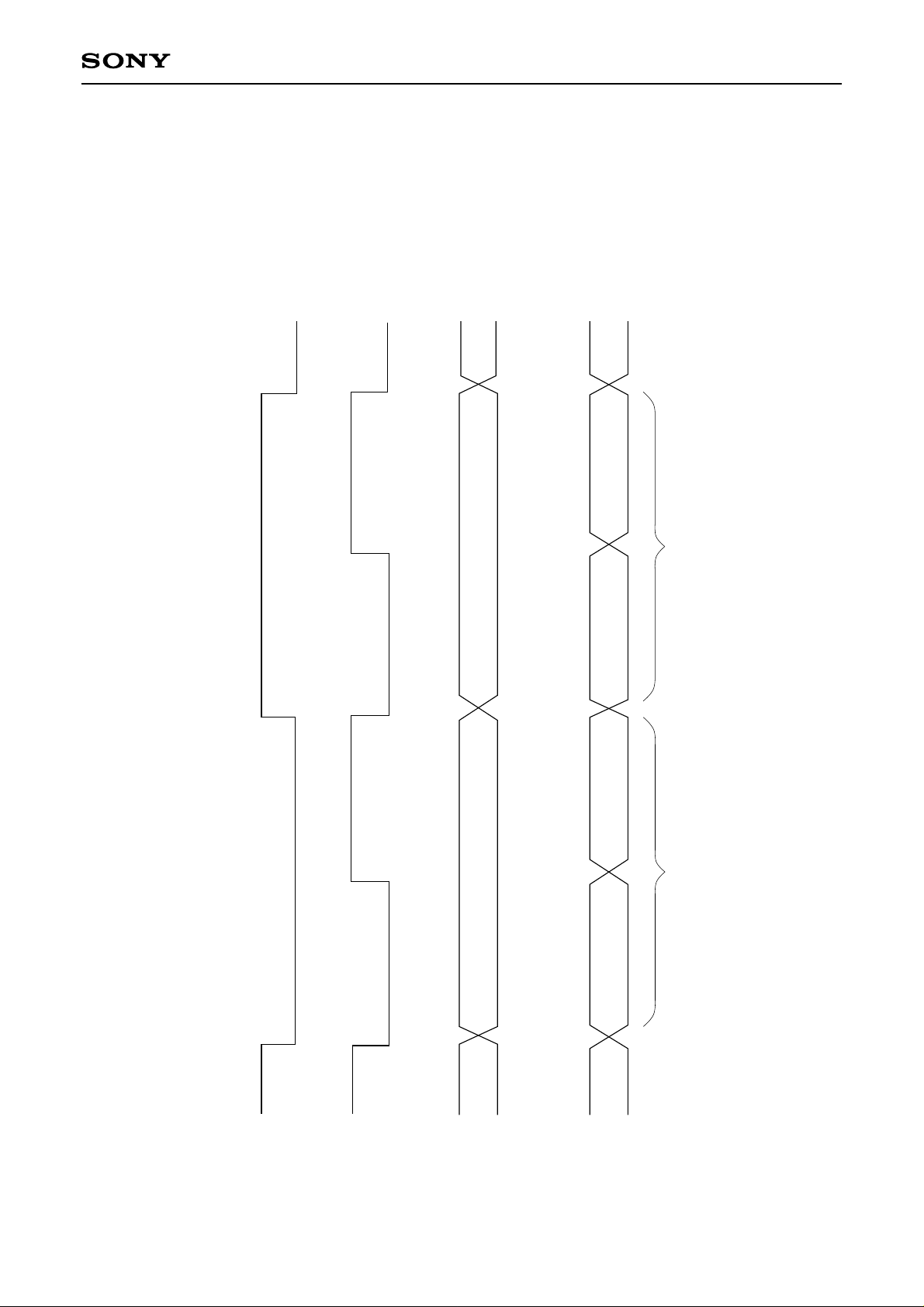
If C2 Pointer = 1,
data is NG
CXD2529Q
Rch 16bit C2 Pointer Lch 16bit C2 Pointer
Lch C2 Pointer
C2 Pointer for upper 8bits C2 Pointer for lower 8bits
Rch C2 Pointer
C2 Pointer for upper 8bits C2 Pointer for lower 8bits
Timing Chart 1-1
LRCK
WDCK
C2PO
CDROM = 0
– 18 –
C2PO
CDROM = 1
Page 19

CXD2529Q
$9X commands (OPSL1 = 0)
Data 1
Command
D3
Function
specifications
D2 D1 D0 D3 D2 D1 D0 D3 D2 D1 D0
DSPB
0
ON/OFF
$9X commands (OPSL1 = 1)
Data 1
Command
D3
Function
specifications
D2 D1 D0 D3 D2 D1 D0 D3 D2 D1 D0
DSPB
0
ON/OFF
∗
Data 2 D0 and subsequent data are DF/DAC function settings.
Data 3 Data 4Data 2
D3 to D1
0 0 0 MCSL
000
D0
SYCOF
OPSL1
∗
Data 2 D0 and subsequent data are DF/DAC function settings.
Data 3 Data 4Data 2
D3 to D1
0 0 1 MCSL
000
D0
SYCOF
OPSL1
CKOSL1 CKOSL0
CKOSL1 CKOSL0
ZDPL ZMUT — —
Data 5
D3
D2 D1 D0
—
———
ZDPL ZMUT 0 0
Data 5
Command bit
DSPB = 1
DSPB = 0
Double-speed playback (CD-DSP block)
Normal-speed playback (CD-DSP block)
Command bit
SYCOF = 1
SYCOF = 0
∗
Set SYCOF = 0 in advance when setting the $AX command LRWO to 1.
LRCK asynchronous mode
Normal operation
Processing
Processing
D3
D2 D1 D0
0 DCOF 0 0
– 19 –
Page 20
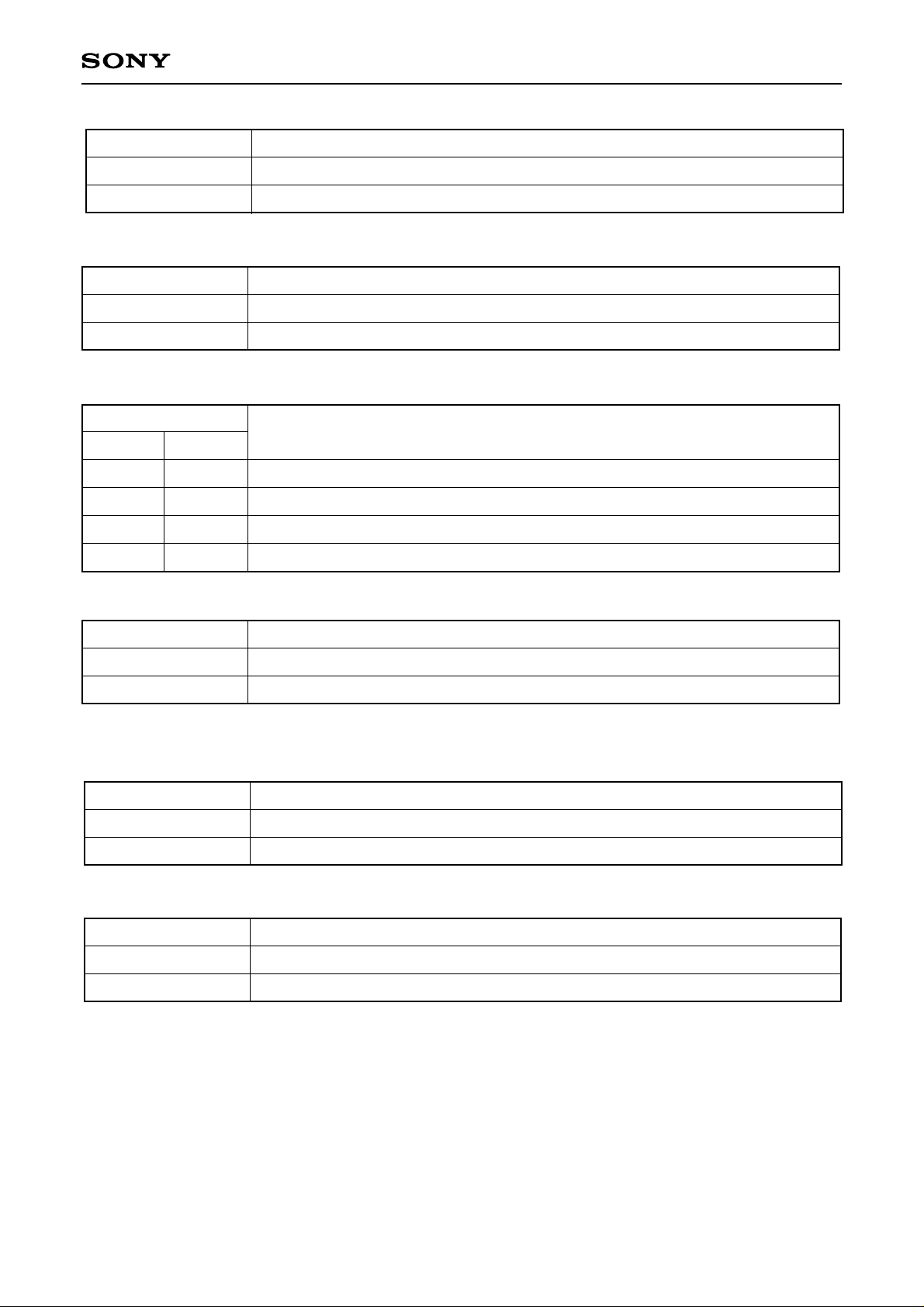
CXD2529Q
Command bit
OPSL1 = 1
OPSL1 = 0
Command bit
MCSL = 1
MCSL = 0
Command bit
CKOSL1 CKOSL0
0
0
1
1
0
1
0
1
Processing
DCOF can be set.
DCOF cannot be set.
Processing
DF/DAC block master clock selection. Crystal = 768Fs (33.8688MHz)
DF/DAC block master clock selection. Crystal = 384Fs (16.9344MHz)
Processing
The CKOUT pin output is 1/1-frequency divided of the crystal input.
The CKOUT pin output is 1/2-frequency divided of the crystal input.
The CKOUT pin output is 1/4-frequency divided of the crystal input.
The CKOUT pin output is fixed to low.
Command bit
ZDPL = 1
ZDPL = 0
∗
See the description of “Mute Flag Output” for the conditions of the mute flag output.
LMUT and RMUT pins are set to high for mute.
LMUT and RMUT pins are set to low for mute.
Command bit
ZMUT = 1
ZMUT = 0
Zero detection mute is on.
Zero detection mute is off.
Command bit
DCOF = 1
DCOF = 0
∗
DCOF can be set when OPSL is 1.
∗
Set the DC offset to off when the zero detection mute is on.
DC offset is off.
DC offset is on.
Processing
Processing
Processing
– 20 –
Page 21

CXD2529Q
$AX commands (OPSL2=0)
Data 1
Command
D3
Audio CTRL
D2 D1 D0 D3 D2 D1 D0
0 0 Mute ATT 0 0 0 EMPH
Data 3
D1 D0
AD9 AD8
D3
AD7 AD6 AD5 AD4 AD3 AD2 AD1 AD0 — — — —
$AX commands (OPSL2 = 1)
Data 1
Command
D3
Audio CTRL
D2 D1 D0 D3 D2 D1 D0
0 0 Mute ATT 0 0 1 EMPH
∗
Data 2 and subsequent data are DF/DAC function settings.
Data 2
Data 3
D3 D2
SMUT 0
OPSL2
Data 4
Data 5
Data 6
D2 D1 D0 D3 D2 D1 D0 D3 D2 D1 D0
∗
Data 2 and subsequent data are DF/DAC function settings.
Data 2
Data 3
D3 D2
SMUT 0
D1 D0
AD9 AD8
Command bit
Mute = 1
Mute = 0
Command bit
ATT = 1
ATT = 0
OPSL2
Data 4
D3
D2 D1 D0 D3 D2 D1 D0 D3 D2 D1 D0
AD7 AD6 AD5 AD4 AD3 AD2 AD1 AD0 FMUT LRWO
Data 5 Data 6Data 3
BSBST
Processing
CD-DSP block mute is on. The zero data is output from the CD-DSP block.
CD-DSP block mute is off.
Processing
Attenuation (–12dB) is applied to the CD-DSP block output.
Attenuation of the CD-DSP block output is off.
BBSL
– 21 –
Page 22

CXD2529Q
Command bit
OPSL2 = 1
OPSL2 = 0
FMUT, LRWO, BSBST and BBSL can be set.
FMUT, LRWO, BSBST and BBSL cannot be set.
Command bit
EMPH = 1
EMPH = 0
∗
If either the EMPHI pin or EMPH is high, de-emphasis is on.
De-emphasis is on.
De-emphasis is off.
Command bit
SMUT = 1
SMUT = 0
∗
If either the SYSM pin or SMUT is high, soft mute is on.
Soft mute is on.
Soft mute is off.
Meaning
Processing
Processing
Command bit
AD9 to 0 Attenuation data
The attenuation data consists of 10 bits, and is set as follows.
Attenuation data
3FFh
3FEh
3FDh
Audio output
0dB
–0.0085dB
–0.017dB
1023 settings are available because the attenuation data
(AD9 to AD0) consists of 10 bits.
The audio output for 001h to 3FFh can be obtained by
the following equation.
:
001h
000h
–60.198dB
–∞
Audio output = 20 log [dB]
Meaning
attenuation data
1024
– 22 –
Page 23
CXD2529Q
Command bit
FMUT = 1
FMUT = 0
∗
FMUT can be set when OPSL2 is 1.
Forced mute is on.
Forced mute is off.
Command bit
LRWO = 1
LRWO = 0
∗
LRWO can be set when OPSL2 is 1.
∗
Set the $9X command SYCOF = 0 in advance when setting LRWO to 1.
Forced sync mode
Normal operation
Note)
Meaning
Meaning
Note) Synchronization is performed at the first LRCK falling edge during reset, so that normally this mode is
unnecessary. However, synchronization can be forcibly applied by setting LRWO to 1.
Command bit
BSBST = 1
BSBST = 0
Bass boost is on.
Bass boost is off.
Processing
∗
BSBSTcan be set when OPSL2 is 1.
Command bit
BBSL = 1
BBSL = 0
∗
BBSL can be set when OPSL2 is 1.
Bass boost is Max.
Bass boost is Mid.
Processing
– 23 –
Page 24
CXD2529Q
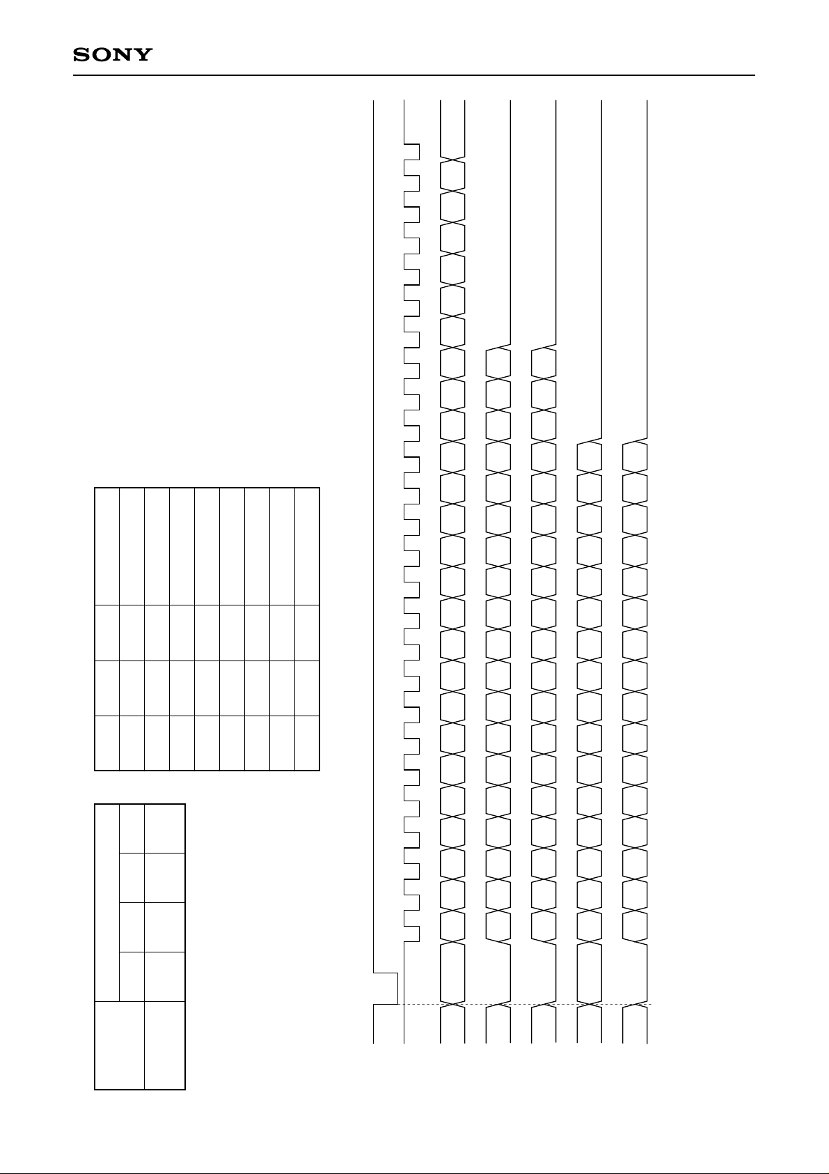
The SQSO pin output can be switched to the various
signals by setting the $8X command SOCT and $BX
commands SL1 and SL0. Set SQCK to high at the falling
edge of XLAT.
Except for Sub Q and peak meter, the signals are loaded
to the register when they are set at the falling edge of
XLAT. Sub Q is loaded to the register with each SCOR,
and peak meter is loaded when a peak is detected.
SubQ
Peak meter
0
SL0 mode
0
SL1
0
SENSDSubQAB
1
0
1
0
1
1
0
0
0
0
1
0
0
1
1
C
0
1
1
1
1
1
SOCT
0
LOCKEMPH RFCKWFCK SCORSPODSPOCSPOB GTOP
CPUSR
Data 1
D2 D1 D0
SL0
D3
SL1
Command
$BX commands
Serial bus
CTRL
XLAT
– 24 –
SQCK
PER1 PER2 PER3 PER4 PER5 PER6 PER7 C1F1 0C1F2 C2F1 0C2F2 FOK LOCKGFS EMPH VF0ALOCK VF1 VF2 VF3 VF4 VF5 VF6 VF7
PER0
mode A
VF0 VF1 VF2 VF3 VF4 VF5 VF6 VF7 ALOCK C1F1 C1F2 0 C2F1 0C2F2 FOK LOCKGFS EMPH
mode B
PER1 PER2 PER3 PER4 PER5 PER6 PER7PER0 C1F1 C1F2 0 C2F1 0C2F2 FOK LOCKGFS EMPH0
mode C
L0 L1 L2 L3 L4 L5 L6 L7 R0 R1 R2 R3 R4 R5 R6 R7
SPOA C1F1 C1F2 C2F1 C2F2XRAOFFOKGFS
mode D
Peak meter
Page 25
CXD2529Q
Signal
PER0 to 7
FOK
GFS
LOCK
EMPH
ALOCK
VF0 to 7
SPOA to D
WFCK
SCOR
GTOP
RFCK
XRAOF
L0 to L7,
R0 to R7
Description
RF jitter amount (used to adjust the focus bias). 8-bit binary data in PER0 = LSB, PER7 = MSB.
Focus OK
High when the frame sync and the insertion protection timing match.
GFS is sampled at 460Hz; when GFS is high, a high signal is output. If GFS is low eight
consecutive samples, a low signal is output.
High when the playback disc has emphasis.
GFS is sampled at 460Hz; when GFS is high eight consecutive samples, a high signal is
output. If GFS is low eight consecutive samples, a low signal is output.
Used during CAV-W mode. Results of measuring the disc rotational velocity.
(See the Timing Chart 2-3.) VF0 = LSB, VF7 = MSB.
SPOA to D pin inputs.
Write frame clock output.
High when either subcode sync S0 or S1 is detected.
High when the sync protection window is released.
Read frame clock output.
Low when the built-in 16K RAM exceeds the ±4 frame jitter margin.
Peak meter register output. L0 to 7 are the left-channel and R0 to 7 are the right-channel peak
data. L0 and R0 are LSB.
C1F1
0
1
1
Command bit
CPUSR = 1
CPUSR = 0
C1F2 C1 correction status C2F1
0
0
1
No Error
Single Error Correction
Irretrievable Error
0
1
1
Processing
XLON pin is high.
XLON pin is low.
C2F2 C2 correction status
0
0
1
No Error
Single Error Correction
Irretrievable Error
– 25 –
Page 26
Peak meter
XLAT
SQCK
CXD2529Q
SQSO
(Peak meter)
L0 L1 L2 L3 L4 L5 L6 L7 R0 R1 R2 R3 R4 R5 R6 R7
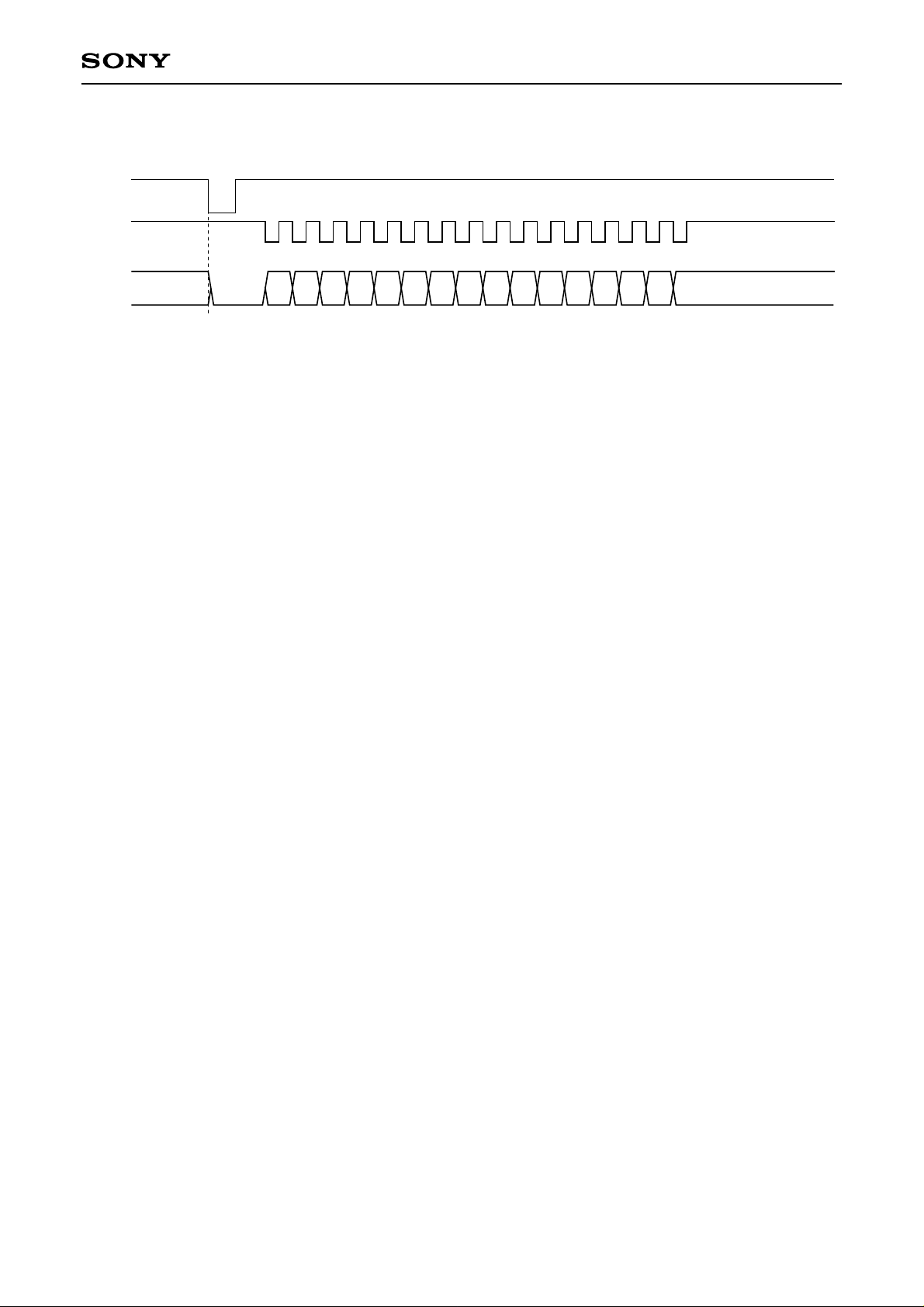
The LSI is set to peak detection mode by setting SOCT = 0, SL1 = 0 and SL0 = 1 with the $8X and $BX
commands. In peak detection mode, the SQSO output is connected to the peak detection register. The
maximum PCM data values (absolute value, upper 8 bits) for the left and right channels can be read out from
SQSO by inputting 16 clocks to SQCK. Peak detection is not performed while inputting to SQCK, and the peak
detection register does not change during readout. This SQCK input is judged using a retriggerable
monostable multivibrator with a time constant of 270 to 400µs. Set the time for which SQCK input is high to
270µs or less. Peak detection restarts from 270 to 400µs after SQCK input.
The peak detection register is reset to zero for each readout (16 clocks input to SQCK). The maximum value
during peak detection mode is detected and held in this condition until the next readout. When setting the LSI
to peak detection mode, perform readout one time initially to reset the peak detection register.
Pre-value hold and average value interpolation data are also detected by peak detection.
– 26 –
Page 27

$CX commands
CXD2529Q
Command
Servo coefficient setting
D3 D2 D1 D0
Gain
MDP1
CLV CTRL ($DX)
• CLV mode gain setting: GCLVS
Gain
MDS1
0
0
0
0
1
1
Gain
MDS0
0
0
1
1
0
0
Gain
CLVS
0
1
0
1
0
1
GCLVS
–12dB
–6dB
–6dB
0dB
0dB
+6dB
• CLVP mode gain setting: GMDP, GMDS
Gain
MDP0
Gain
MDS1
Gain
MDS0
Gain
CLVS
Gain
MDP1
0
0
1
Gain
MDP0
0
1
0
GMDP
–6dB
0dB
+6dB
Gain
MDS1
0
0
1
Gain
MDS0
0
1
0
GMDS
–6dB
0dB
+6dB
– 27 –
Page 28
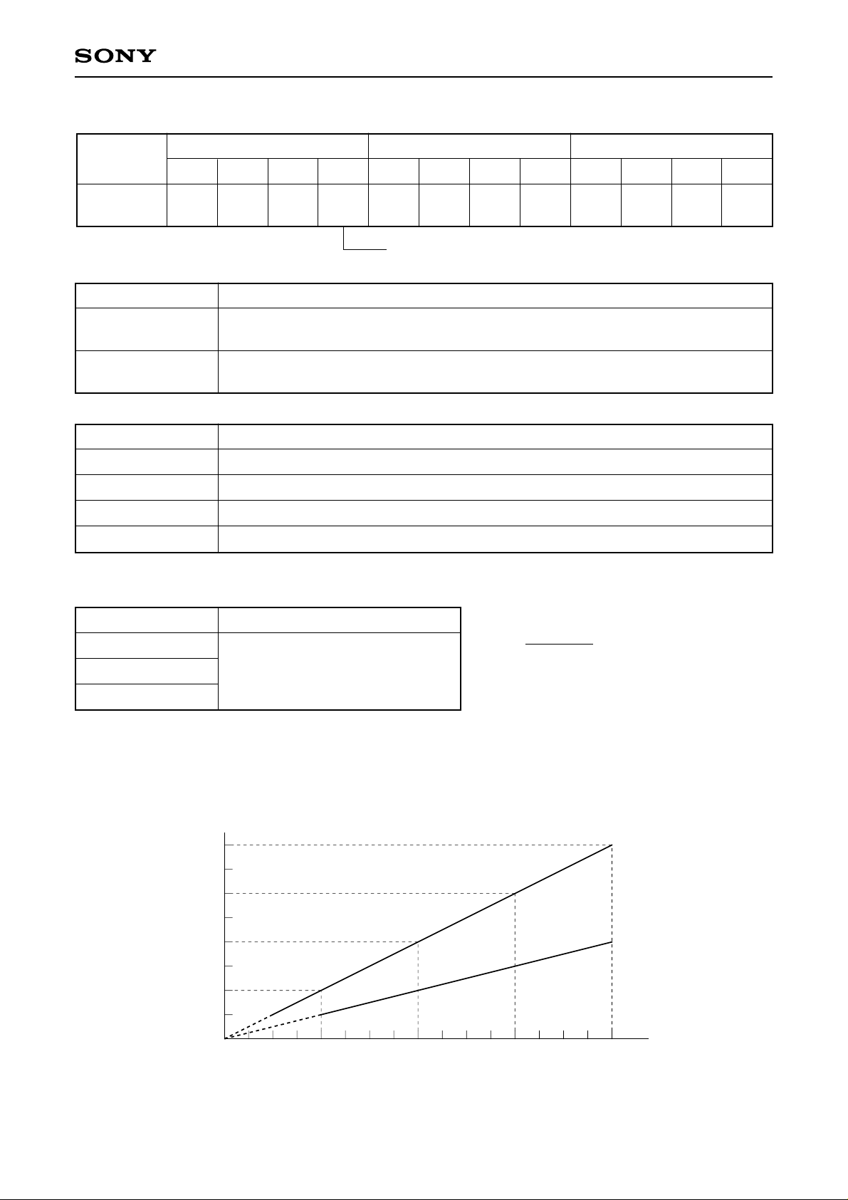
$DX commands
CXD2529Q
Command
Data 1 Data 2
CLV CTRL
D3
DCLV
PWM MD
D2 D1 D0 D3 D2 D1 D0 D3 D2 D1 D0
TB TP
Gain
CLVS
VP7 VP6 VP5 VP4 VP3 VP2 VP1 VP0
See the $CX commands.
Command bit Description
DCLV PWM MD = 1
DCLV PWM MD = 0
Digital CLV PWM mode specified. Both MDS and MDP are used. CLV-W and
CAV-W modes can not be used.
Digital CLV PWM mode specified. Ternary MDP values are output. CLV-W and
CAV-W modes can be used.
Command bit Description
TB = 0
TB = 1
TP = 0
TP = 1
Bottom hold at a cycle of RFCK/32 in CLVS mode.
Bottom hold at a cycle of RFCK/16 in CLVS mode.
Peak hold at a cycle of RFCK/4 in CLVS mode.
Peak hold at a cycle of RFCK/2 in CLVS mode.
Data 3
The rotational velocity R of the spindle can be
expressed with the following equation.
Command bit Description
256 – n
VP0 to 7 = F0 (H)
.
.
.
VP0 to 7 = E0 (H)
Playback at half (normal) speed
to
Playback at normal (double) speed
R =
32
R: Relative velocity at normal speed = 1
n: VP0 to 7 setting value
Note)
• Values in parentheses are for when DSPB is 1.
• Values when crystal is 16.9344 MHz and XTSL is low or when crystal is 33.8688 MHz and XTSL is high.
• VP0 to 7 setting values are valid in CAV-W mode.
2
1.5
1
0.5
R–Relative velocity [multiple]
DSPB = 1
DSPB = 0
F0 E0
VP0 to 7 setting value [HEX]
Fig. 1-1
– 28 –
Page 29
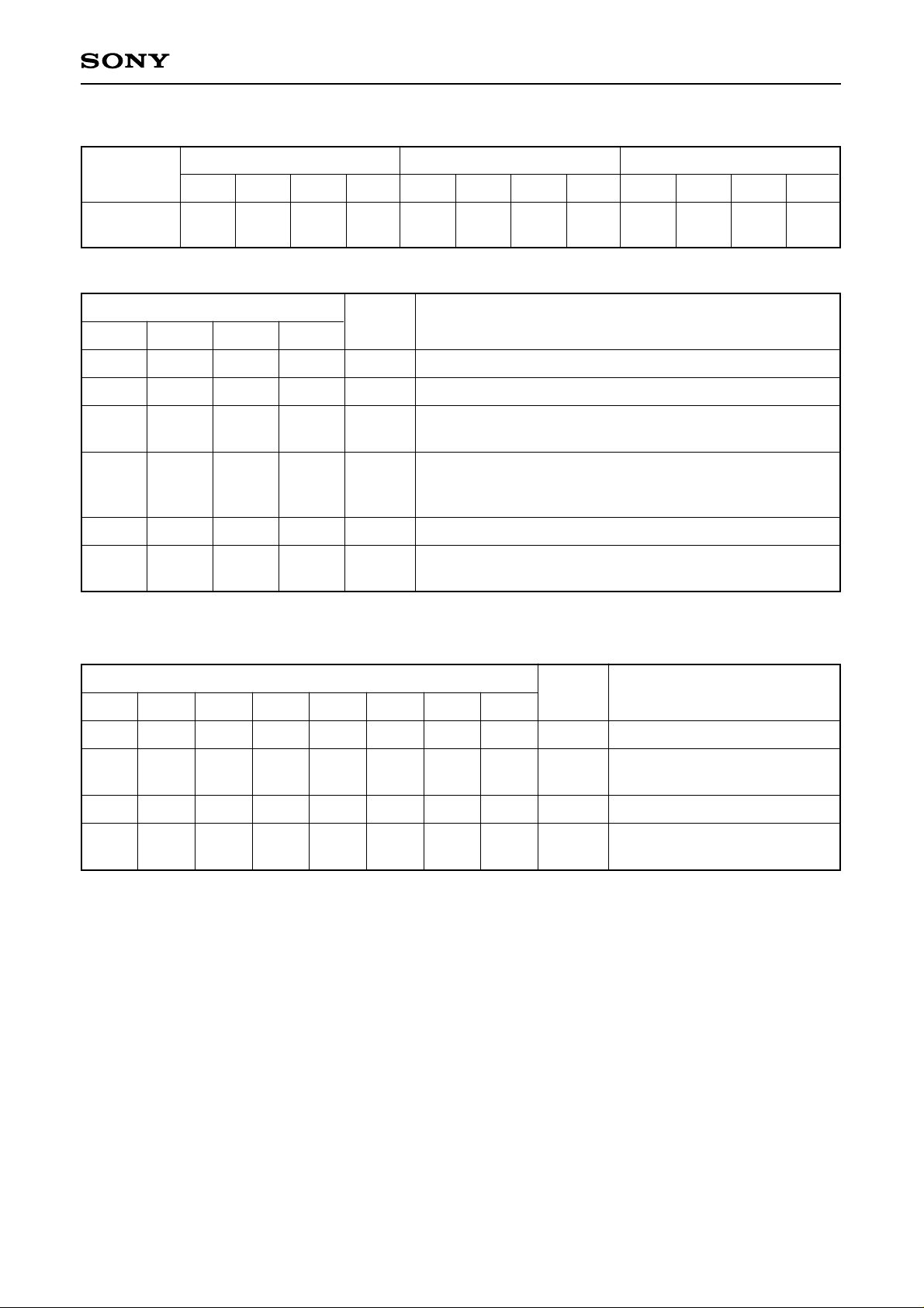
$EX commands
CXD2529Q
Command
Data 1
D3 D2 D1 D0
CLV mode CM3 CM2 CM1 CM0
Command bit
CM3 CM2 CM1
0
1
1
1
1
0
∗1
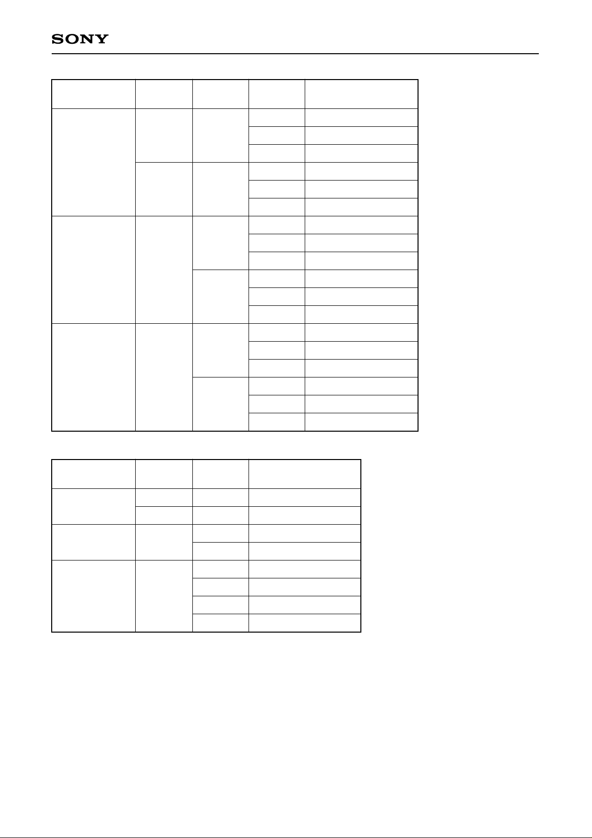
See the Timing Charts 1-2 to 1-7.
0
0
0
1
1
1
0
0
1
1
1
1
CM0
0
0
0
0
1
0
Mode
STOP
KICK
BRAKE
CLVS
CLVP
CLVA
Data 2
D3 D2 D1 D0
EPWM SPDC ICAP SFSL
D3 D2 D1 D0
VC2C HIFC LPWR VPON
Data 3
Description
Spindle stop mode.
Spindle forward rotation mode.
∗1
∗1
Spindle reverse rotation mode. Valid only when LPWR = 0,
in any modes.
∗1
Rough servo mode. When the RF-PLL circuit isn’t locked,
this mode is used to adjust the disc rotations within the RFPLL capture range.
PLL servo mode.
Automatic CLVS/CLVP switching mode.
Used for normal playback.
Command bit
Mode
EPWM SPDC ICAP
0
0
0
1
∗2
Figs. 3-1 and 3-2 show the control flow with the microcomputer software in CLV-W mode.
0
0
1
0
SFSL
0
0
1
1
VC2C
0
0
0
0
HIFC
0
1
0
0
LPWR
0
1
1
1
VPON
0
0
0
0
0
CLV-N
0
CLV-W
1
CAV-W
1
CAV-W
Crystal reference CLV servo.
Used for playback in CLV-W
mode.
Spindle control with VP0 to 7.
Spindle control with the
external PWM.
Description
∗2
– 29 –
Page 30
CXD2529Q
Command
SPD mode
Gain
CAV1
0
0
1
1
Command bit
FCSW = 0
FCSW = 1
Data 4
D3 D2 D1 D0
Gain
CAV1
Gain
CAV0
0
1
0
1
Gain
CAV0
Gain
0dB
–6dB
–12dB
–18dB
FCSW 0
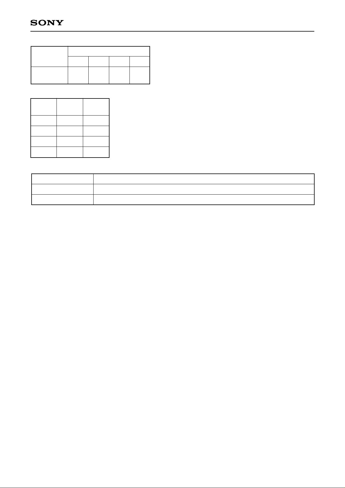
The VPCO2 pin is not used and is high impedance.
The VPCO2 pin is used and the pin signal is the same as VPCO1.
• This sets the gain when controlling the spindle with the phase comparator
in CAV-W mode.
Processing
– 30 –
Page 31
CXD2529Q
Mode
CLV-N
CLV-W
CAV-W
DCLV
PWM MD
0
1
0
0
LPWR
0
0
0
1
0
Command
KICK
BRAKE
STOP
KICK
BRAKE
STOP
KICK
BRAKE
STOP
KICK
BRAKE
STOP
KICK
BRAKE
STOP
KICK
Timing chart
1-2 (a)
1-2 (b)
1-2 (c)
1-3 (a)
1-3 (b)
1-3 (c)
1-4 (a)
1-4 (b)
1-4 (c)
1-5 (a)
1-5 (b)
1-5 (c)
1-6 (a)
1-6 (b)
1-6 (c)
1-7 (a)
Mode
DCLV
PWM MD
0
1
LPWR
0
BRAKE
STOP
Timing chart
1-8
1-7 (b)
1-7 (c)
CLV-N
CLV-W
CAV-W
1
0
0
0
0
1
0
1
0
1
1-12 (EPWM = 0)
1-13 (EPWM = 0)
1-14 (EPWM = 1)
1-15 (EPWM = 1)
1-9
1-10
1-11
Note) The CLV-W and CAV-W modes support control only by the ternary output of the MDP pin. Therefore,
when using the CLV-W and CAV-W modes, set DCLV PWM MD to 0.
– 31 –
Page 32
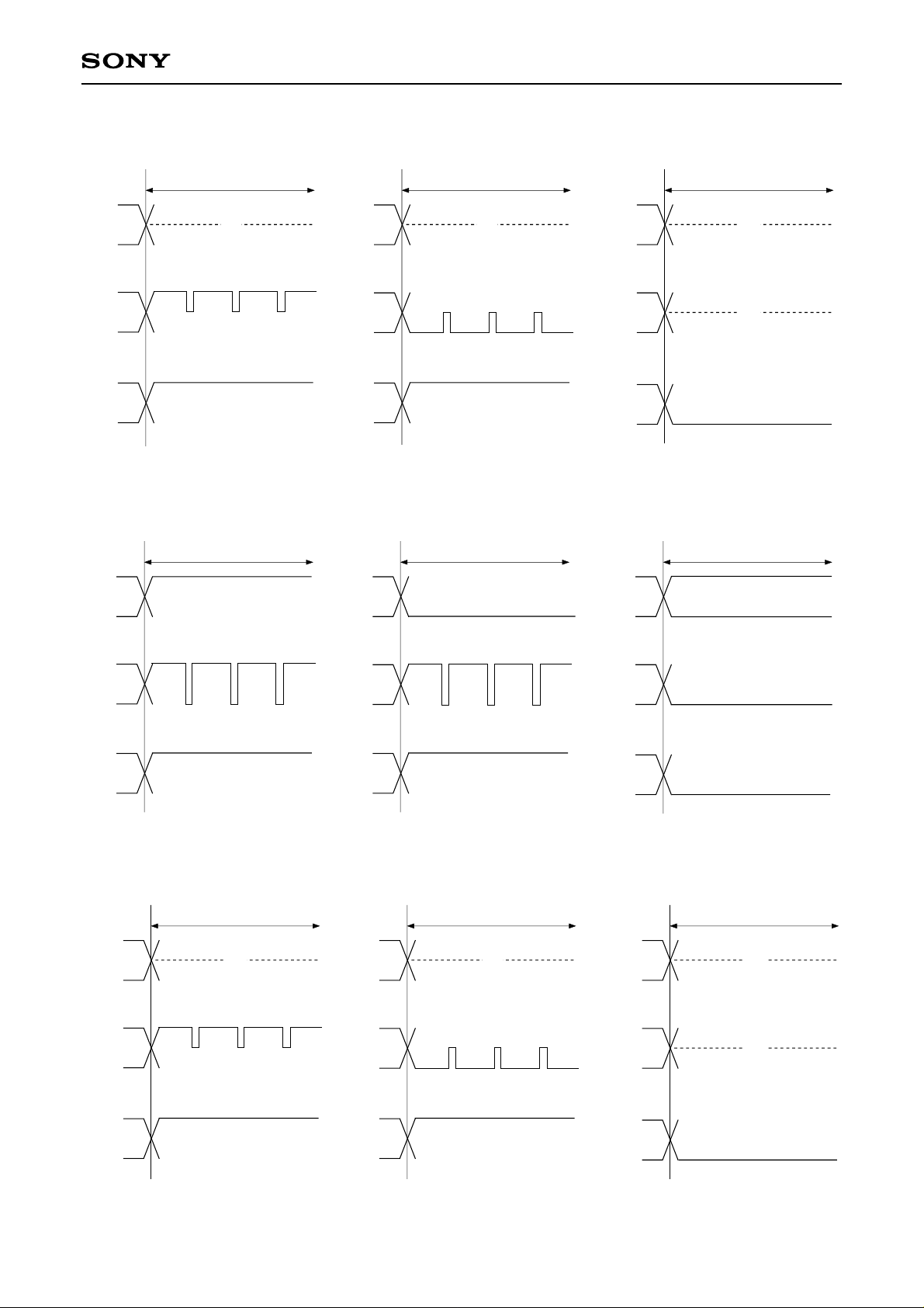
Timing Chart 1-2
CLV-N mode DCLV PWM MD = LPWR = 0
KICK
BRAKE
CXD2529Q
STOP
Z
(a) KICK
Z
H
MDS
MDP
MON
MDS
MDP
MON
H
Timing Chart 1-3
CLV-N mode DCLV PWM MD = 1, LPWR = 0
KICK
MDS
MDP
H
H
L
MDS
MDP
L
H
Z
(b) BRAKE
BRAKE
L
Z
H
L
MDS
MDP
MON
MDS
MDP
Z
Z
L
(c) STOP
STOP
L
MON
H
(a) KICK
MON
H
(b) BRAKE
MON
(c) STOP
Timing Chart 1-4
CLV-W mode (when following the spindle rotational velocity) DCLV PWM MD = LPWR = 0
MDS
MDP
MON
KICK
Z
H
Z
H
(a) KICK
MDS
MDP
MON
L
BRAKE
Z
(b) BRAKE
Z
H
MDS
MDP
MON
(c) STOP
L
STOP
Z
Z
L
– 32 –
Page 33

Timing Chart 1-5
CLV-W mode (when following the spindle rotational velocity) DCLV PWM MD = 0, LPWR = 1
CXD2529Q
KICK
Z
(a) KICK
Z
H
MDS
MDP
MON
MDS
MDP
MON
H
Timing Chart 1-6
CAV-W mode DCLV PWM MD = LPWR = 0
KICK
MDS
Z
MDS
BRAKE
Z
Z
H
(b) BRAKE
BRAKE
Z
MDS
MDP
MON
MDS
STOP
Z
Z
L
(c) STOP
STOP
Z
MDP
MON
H
H
(a) KICK
MDP
MON
Timing Chart 1-7
CAV-W mode DCLV PWM MD = 0, LPWR = 1
KICK
MDS
MDP
Z
H
MDS
MDP
L
H
(b) BRAKE
BRAKE
Z
Z
MDP
MON
MDS
MDP
Z
H
(c) STOP
STOP
Z
Z
MON
H
(a) KICK
MON
(b) BRAKE
– 33 –
H
MON
H
(c) STOP
Page 34
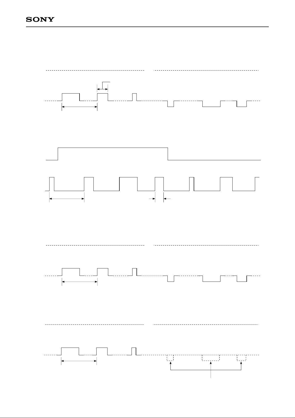
Timing Chart 1-8
CLV-N mode DCLV PWM MD = LPWR = 0
CXD2529Q
MDS
n · 236 (ns) n = 0 to 31
Acceleration
MDP
132kHz
7.6µs
Timing Chart 1-9
CLV-N mode DCLV PWM MD = 1, LPWR = 0
MDS
Acceleration Deceleration
MDP
132kHz
7.6µs
Z
Z
Deceleration
n · 236 (ns) n = 0 to 31
Timing Chart 1-10
CLV-W mode DCLV PWM MD = LPWR = 0
MDS
Acceleration
MDP
264kHz
3.8µs
Timing Chart 1-11
CLV-W mode DCLV PWM MD = 0, LPWR = 1
MDS
Acceleration
MDP
264kHz
3.8µs
Z
Z
Deceleration
Z
Z
– 34 –
The BRAKE pulse is masked when LPWR = 1.
Page 35
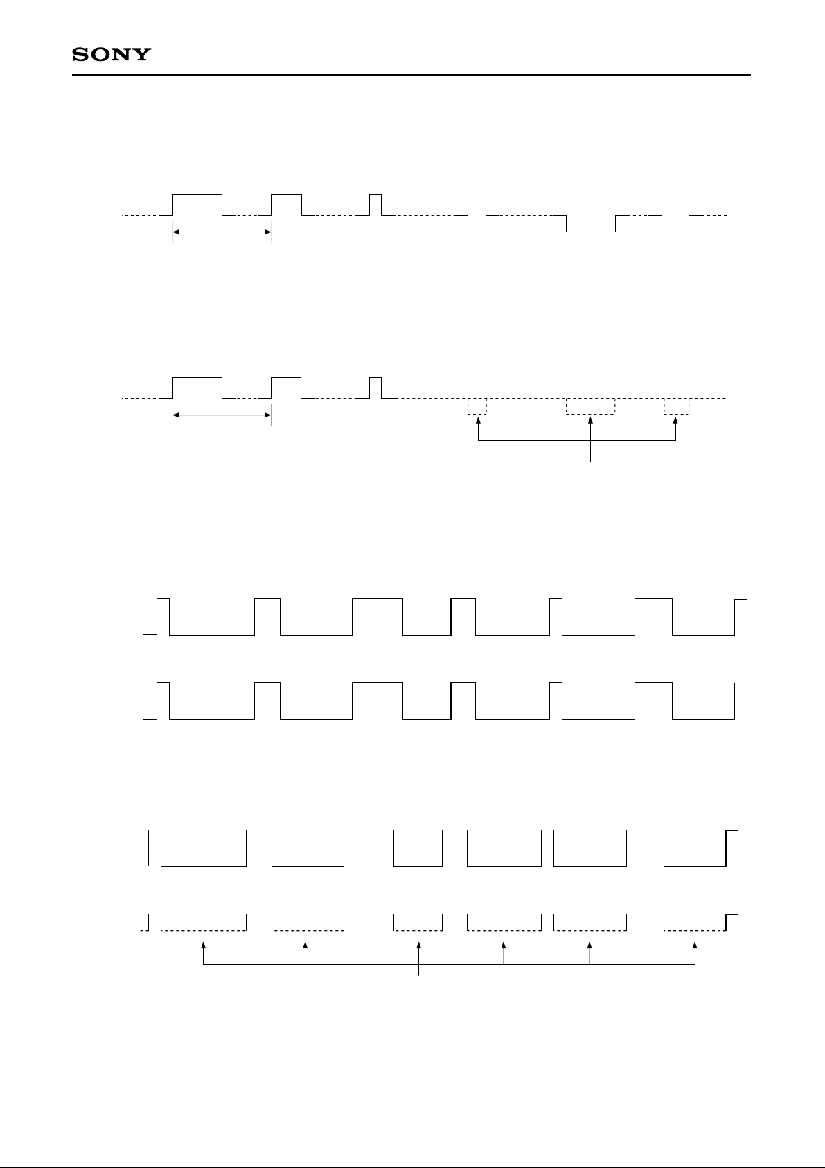
Timing Chart 1-12
CAV-W mode EPWM = DCLV PWM MD = LPWR = 0
Acceleration
CXD2529Q
MDP
264kHz
3.8µs
Timing Chart 1-13
CAV-W mode EPWM = DCLV PWM MD = 0, LPWR = 1
Acceleration
MDP
264kHz
3.8µs
Timing Chart 1-14
CAV-W mode EPWM = 1, DCLV PWM MD = LPWR = 0
H
PWMI
L
Z
Deceleration
Z
The BRAKE pulse is masked when LPWR = 1.
H
MDP
L
Acceleration
Deceleration
Timing Chart 1-15
CAV-W mode EPWM = 1, DCLV PWM MD = 0, LPWR = 1
H
PWMI
H
MDP
L
Acceleration
Z
The BRAKE pulse is masked when LPWR = 1.
Note) The CLV-W and CAV-W modes support control only by the ternary output of the MDP pin.
Therefore, when using the CLV-W and CAV-W modes, set DCLV PWM MD to 0.
– 35 –
Page 36
CXD2529Q
1-2. Description of SENS Output
The following signals are output from SENS, depending on the microcomputer serial register value (latching
not required).
Microcomputer serial register
value (latching not required)
$0X, 1X, 2X, 3X
$4X
$5X
$6X
$AX
$EX
$7X, 8X, 9X, BX,
CX, DX, FX
SENS
output
SEIN
XBUSY
FOK
SEIN
GFS
OV64
“L”
Meaning
SEIN, a signal input to this LSI from the SSP, is output.
Low while the auto sequencer is in operation, high when operation
terminates.
Outputs the signal input to the FOK pin. Normally, FOK (from RF) is
input. High for “focus OK”.
SEIN, a signal input to this LSI from the SSP, is output.
High when the regenerated frame sync is obtained with the correct
timing.
Low when the EFM signal, after passing through the sync detection
filter, is lengthened by 64 channel clock pulses or more.
SENS pin is fixed to low.
Note that the SENS output can be read out from the SQSO pin when SOCT = 0, SL1 = 1 and SL0 = 0. (See
the $BX commands.)
2. Subcode Interface
This section explains the subcode interface.
There are two methods for reading out a subcode externally. The 8-bit subcodes P to W can be read out from
SBSO by inputting EXCK to the CXD2529Q.
Sub Q can be read out after the CRC check of the 80 bits of data in the subcode frame. This is accomplished,
after checking SCOR and CRCF, by inputting 80 clock pulses to SQCK and reading out the data from the
SQSO pin.
2-1. P to W Subcode Read
Data can be read out by inputting EXCK immediately after WFCK falls. (See the Timing Chart 2-1.)
2-2. 80-bit Sub Q Read
Fig. 2-1 shows the peripheral block of the 80-bit Sub Q register.
• First, Sub Q, regenerated at one bit per frame, is input to the 80-bit serial/parallel register and the CRC check
circuit.
• 96-bit Sub Q is input, and if the CRC is OK, it is output to SQSO with CRCF = 1. In addition, the 80 bits are
loaded into the parallel/serial register.
When SQSO goes high 400µs or more (monostable multivibrator time constant) after the subcode is read
out, the CPU determines that new data (which passed the CRC check) has been loaded.
• In the CXD2529Q, when 80-bit data is loaded, the order of the MSB and LSB is inverted for each byte. As a
result, although the sequence of bytes is the same, the bits within the bytes are now ordered LSB first.
• Once the fact that the 80-bit data has been loaded is confirmed, SQCK is input so that the data can be read
out. In the CXD2529Q, the SQCK input is detected, and when it is low the retriggerable monostable
multivibrator is reset.
• The retriggerable monostable multivibrator has a time constant from 270 to 400µs. When the duration for
which SQCK is high is less than this time constant, the monostable multivibrator is kept reset; during this
interval, the S/P register is not loaded into the P/S register.
• While the monostable multivibrator is being reset, data cannot be loaded in the 80-bit parallel/serial register.
In other words, while reading out with a clock cycle shorter than the monostable multivibrator time constant,
the register is not rewritten by CRCOK, etc. (See the Timing Chart 2-2.)
• Although a clock is input from the SQCK pin to actually perform these operations, the high and low intervals
for this clock should be between 750ns and 120µs.
– 36 –
Page 37
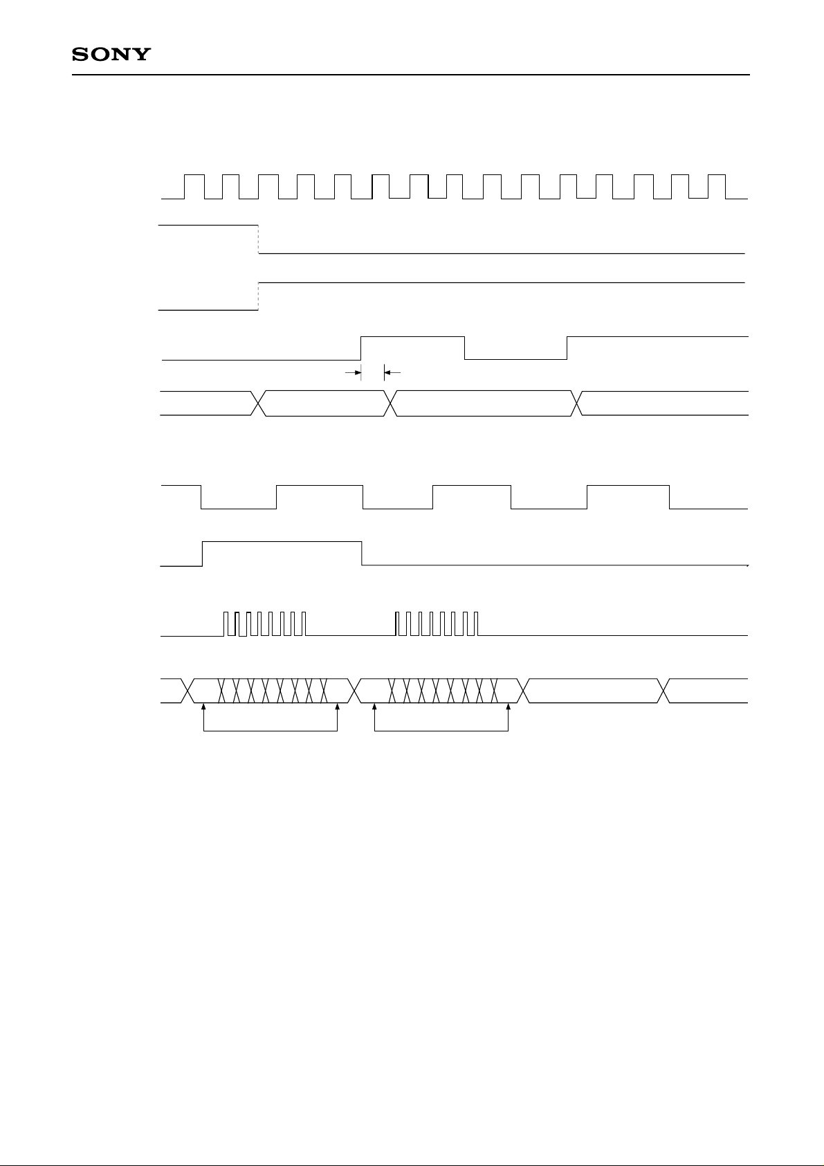
Timing Chart 2-1
Internal
PLL clock
4.3218 ± ∆MHz
WFCK
SCOR
CXD2529Q
EXCK
SBSO
WFCK
SCOR
EXCK
SBSO
S0 · S1 Q R
S0•S1 Q R S T U V W
Same Same
400ns max.
S0•S1
P1 Q R S T U V W P1 P2 P3
Sub Code P.Q.R.S.T.U.V.W Read Timing
– 37 –
Page 38

ADDRS CTRL
CXD2529Q
SO
SQCK
8
SQSO
LD
(AMIN)
8
8
8
8
8
8
80bit S/P Register
8
LD
LD
LD
LD
80bit P/S Register
LD
SHIFT
SHIFT
Mono/Multi
CRCF
Mix
(ASEC)
(AFRAM)
A B C D E F G H
SIN
SUBQ
Fig. 2-1. Block Diagram
Order
Inversion
8
LD
LD
H G F E D C B A
SI
SUBQ
CRCC
– 38 –
Page 39

CTL3
CXD2529Q
98
95 96 97
91 92 93 94
CRCF2
CTL2
CTL1
L
CTL0
3
ADR3
2
1
Determined by mode
270 to 400µs for SQCK = High
ADR2
80 Clock
Order
Inversion
3
2
1
CRCF1
WFCK
SCOR
SQSO
Registere load forbidder
SQCK
750ns to 120µs
Mono/multi (Internal)
SQCK
ADR1
ADR0
CRCF
SQSO
300ns max.
Timing Chart 2-2
– 39 –
Page 40
Timing Chart 2-3
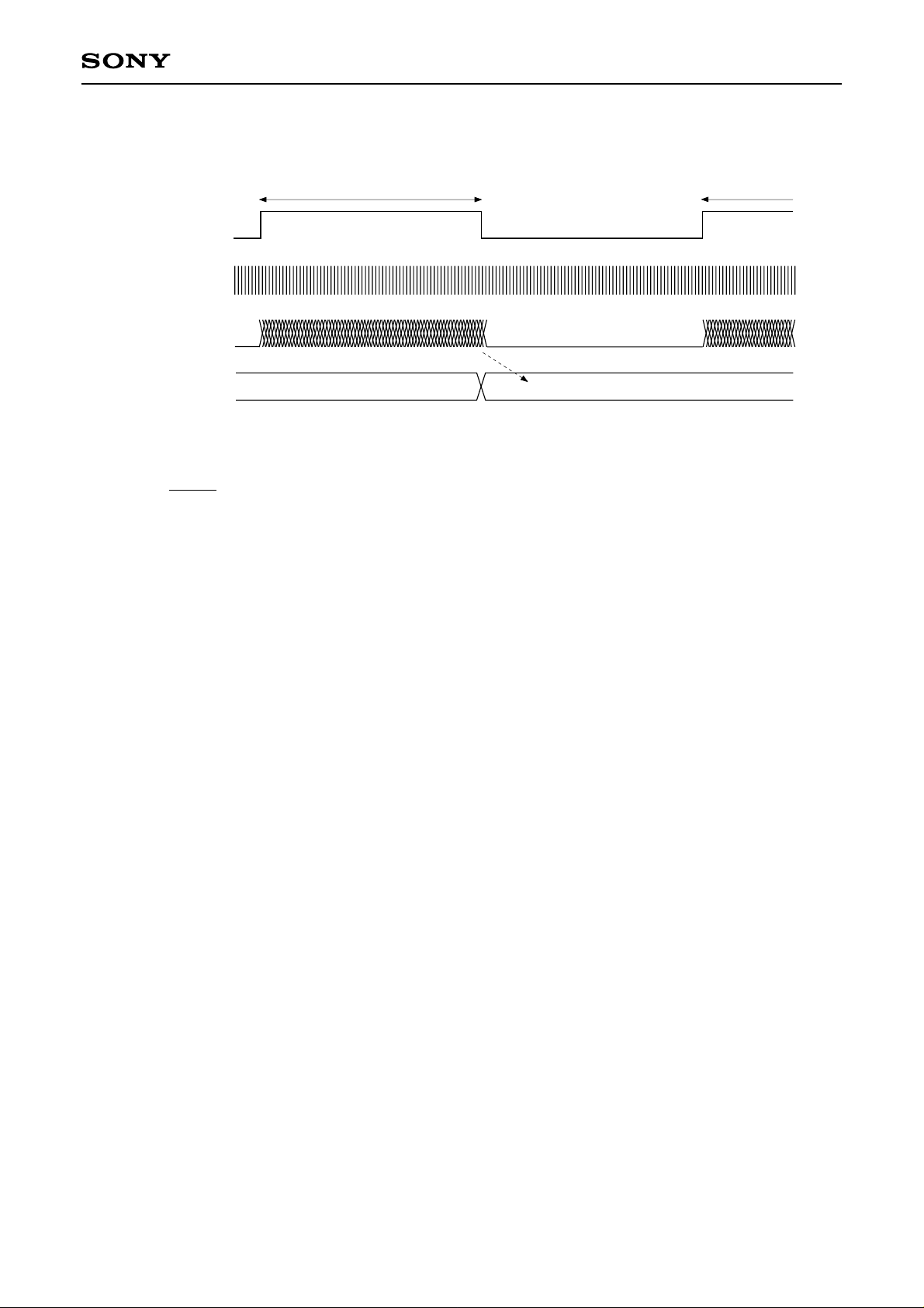
Reference window
(132.2kHz)
CXD2529Q
Measurement interval
(approximately 3.8µs)
Measurement pulse
Measurement counter
(VCKI/2)
VF0 to 7
Load
m
The relative velocity R of the disc can be expressed with the following equation.
m + 1
R = (R: Relative velocity, m: Measurement results)
32
VF0 to 7 is the result obtained by counting VCKI/2 pulses while the reference signal (132.2kHz) generated
from the crystal (384Fs) is high. This count is 31 when the disc is rotating at normal speed and 63 when it is
rotating at double speed (when DSPB is low).
– 40 –
Page 41

CXD2529Q
3. Description of Modes
This LSI has three basic operating modes using a combination of spindle control and the PLL. The operations
for each mode are described below.
3-1. CLV-N mode
This mode is compatible with the CXD2507AQ, and operation is the same as the CXD2507AQ. Accordingly,
the PLL capture range is ±150kHz.
3-2. CLV-W mode
This is the wide capture range mode. This mode allows the PLL to follow the rotational velocity of the disc.
This rotational following control has two types: using the built-in VCO2 or providing an external VCO. The
spindle is the CLV servo like the CXD2507AQ. Operation using the built-in VCO2 is described below. (When
using an external VCO, input the signal from the VPCO pin to the low-pass filter, use the output from the lowpass filter as the control voltage for the external VCO, and input the oscillation from the VCO to the VCKI
pin.)
While starting to rotate a disc and/or speeding up to the lock range speed from the condition that a disc
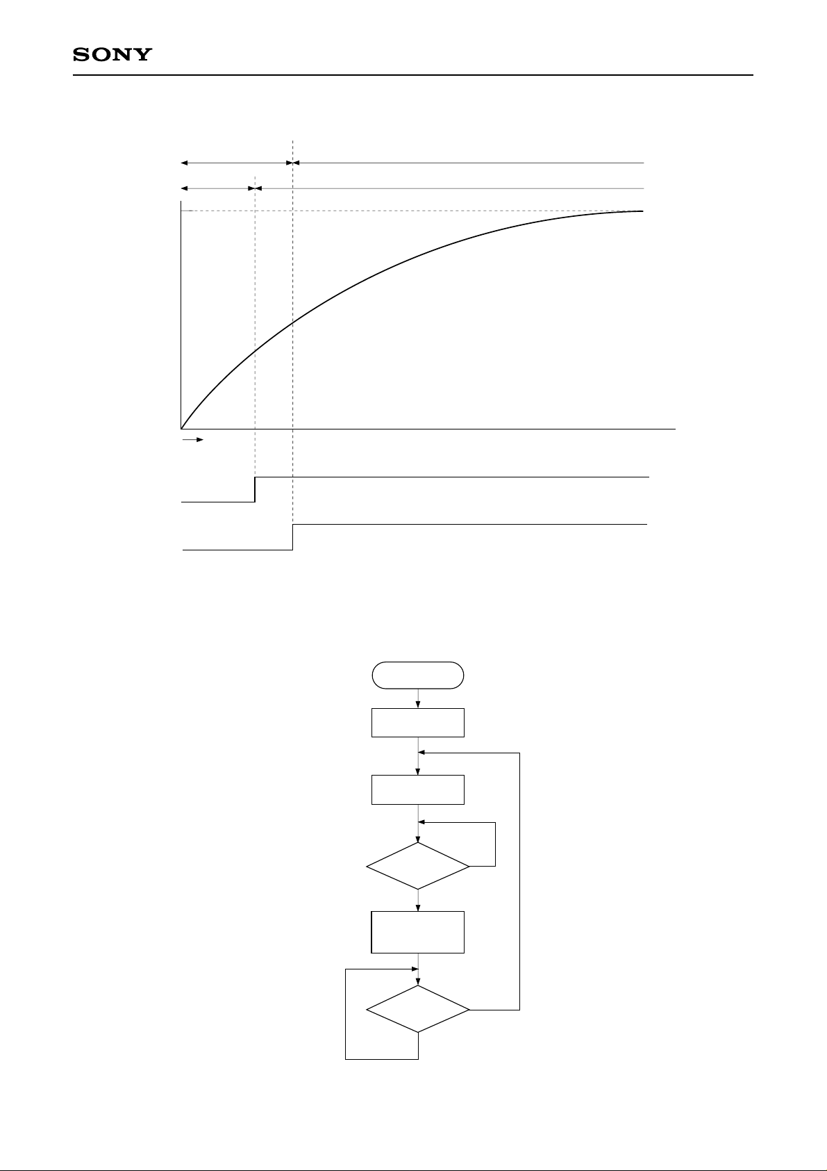
stops, CAV-W mode should be used. Specifically, first send $E665X to set CAV-W mode and kick a disc,
then send $E60C to set CLV-W mode if ALOCK is high, which can be read out serially from the SQSO pin.
CLV-W mode is used for playback while ALOCK is high. The microcomputer monitors the serial data output,
and must return to adjust-speed operation (CAV-W mode) when ALOCK becomes low. The control flow
according to the microcomputer software in CLV-W mode is shown in Fig. 3-2.
In CLV-W mode (normal), low power consumption is achieved by setting LPWR to high. Control was formerly
performed by applying acceleration and deceleration pulses to the spindle motor. However, when LPWR is
set to high, deceleration pulses are not output, thereby achieving low power consumption mode.
CLV-W mode supports control only by the ternary output of the MDP pin. Therefore, when using CLV-W
mode, set DCLV PWM MD to low.
Note) The capture range for this mode is theoretically up to the signal processing limit.
3-3. CAV-W mode
This is the CAV mode. In this mode, the external clock is fixed but the spindle rotational velocity can be
controlled as desired. The rotational velocity is determined by the VP0 to 7 setting values or the external
PWM. When controlling the spindle with VP0 to 7, setting the CAV-W mode with the $E665 command and
controlling VP0 to 7 with the $DX commands allows the rotational velocity to be varied from low speed to
double speed. (See the $DX commands.) Also, when controlling the spindle with the external PWM, the
PWMI pin is binary input which becomes KICK during high intervals and BRAKE during low intervals.
The microcomputer can know the rotational velocity using the V16M oscillation frequency. The reference
frequency for the velocity measurement is the 132.3kHz signal obtained by dividing the crystal (384Fs) by
128. The velocity is obtained by counting V16M/2 pulses while the reference is high, and the result is output
from the new CPU interface as 8 bits (VP0 to 7). These measurement results are 31 when the disc is rotating
at normal speed or 63 when it is rotating at double speed. These values match those of the 256-n for control
with VP0 to 7.
In CAV-W mode, the spindle is set to the desired rotational velocity and the operation speed for the entire
system follows this rotational velocity. Therefore, the cycles for the Fs system clock, PCM data and all other
output signals from this LSI change according to the rotational velocity of the disc (except for DATO, CLKO
and XLTO).
Note) The capture range for this mode is theoretically up to the signal processing limit.
– 41 –
Page 42
CXD2529Q
Rotational velocity
Target velocity
LOCK
ALOCK
CAV-W
CLVS
KICK
CLV-W
CLVP
Operation mode
Spindle mode
Time
CLV-W Mode
Fig. 3-1. Disc Stop to Normal Condition in CLV-W Mode
CLV-W MODE
START
KICK $E800
Mute OFF $A000
CAV-W $E665
(CLVA)
NO
ALOCK = H ?
YES
CLV-W $E60C
(CLVA)
(WFCK PLL)
ALOCK = L ?
YES
NO
Fig. 3-2. CLV-W Mode Flow Chart
– 42 –
Page 43

CXD2529Q
4. Description of Other Functions
4-1. Channel Clock Regeneration by the Digital PLL Circuit
• The channel clock is necessary for demodulating the EFM signal regenerated by the optical system.
Assuming T as the channel clock cycle, the EFM signal is modulated in an integer multiple of T from 3T to
11T. In order to read out the information in the EFM signal, this integer value must be read correctly. As a
result, T, that is the channel clock, is necessary.
In an actual player, PLL is necessary to regenerate the channel clock because the fluctuation in the spindle
rotation alters the width of the EFM signal pulses.
The block diagram of this PLL is shown in Fig. 4-1.
The CXD2529Q has a built-in three-stage PLL.
• The first-stage PLL is for the wide-band PLL. When the built-in VCO2 is used, LPF is required externally.
When the built-in VCO2 is not used, LPF and VCO are required externally.
The output of this first-stage PLL is used as a reference for all clocks within the LSI.
• The second-stage PLL generates a high-frequency clock needed by the third-stage digital PLL.
• The third-stage PLL is a digital PLL that regenerates the actual channel clock.
• The new digital PLL in CLV-W mode follows the rotational velocity of the disc, in addition to the
conventional secondary loop.
– 43 –
Page 44

Block Diagram 4-1
CXD2529Q
CLV-W
CAV-W
Spindle rotation information
X'tal
XTSL
OSC
2/1 MUX
1/2 1/32
1/2
Microcomputer
control
VPON
1/n
n = 1 to 256
(VP7 to 0)
1/K
(KSL1, 0)
1/M
Phase comparator
VCOSEL2
VCO2
CLV-N
CLV-W
CAV-W
Selector
/CLV-N
VPCO
LPF
VCTL
V16M
VCKI
Digital PLL
(KSL3, 2)
CXD2529Q
1/N
1/K
RFPLL
Phase comparator
VCO1
VCOSEL1
PCO
FILI
FILO
CLTV
– 44 –
Page 45
CXD2529Q
4-2. Frame Sync Protection
• In a CD player operating at normal speed, a frame sync is recorded approximately every 136µs (7.35kHz).
This signal is used as a reference to know which data is the data within a frame. Conversely, if the frame
sync cannot be recognized, the data is processed as error data because it cannot be recognized what the
data is. As a result, recognizing the frame sync properly is extremely important for improving playability.
• In the CXD2529Q, window protection and forward protection/backward protection have been adopted for
frame sync protection. The adoption of these functions achieves very powerful frame sync protection.
There are two window widths: one for cases where a rotational disturbance affects the player and the other
for cases where there is no rotational disturbance (WSEL = 0/1). In addition, the forward protection counter is
fixed to 13, and the backward protection counter is fixed to 3. In other words, when the frame sync is being
played back normally and then cannot be detected due to scratches or other problems, a maximum of 13
frames are inserted. If the frame sync cannot be detected for 13 frames or more, the window is released and
the frame sync is resynchronized.
In addition, immediately after the window is released and resynchronization is executed, if a proper frame
sync cannot be detected within 3 frames, the window is released immediately.
4-3. Error Correction
• In the CD format, one 8-bit data contains two error correction codes, C1 and C2. For C1 correction, the code
is created with 28-byte information and 4-byte C1 parity.
For C2 correction, the code is created with 24-byte information and 4-byte parity.
Both C1 and C2 are Reed-Solomon codes with a minimum distance of 5.
• The CXD2529Q SEC strategy provides excellent playability through powerful frame sync protection and C1
and C2 error corrections.
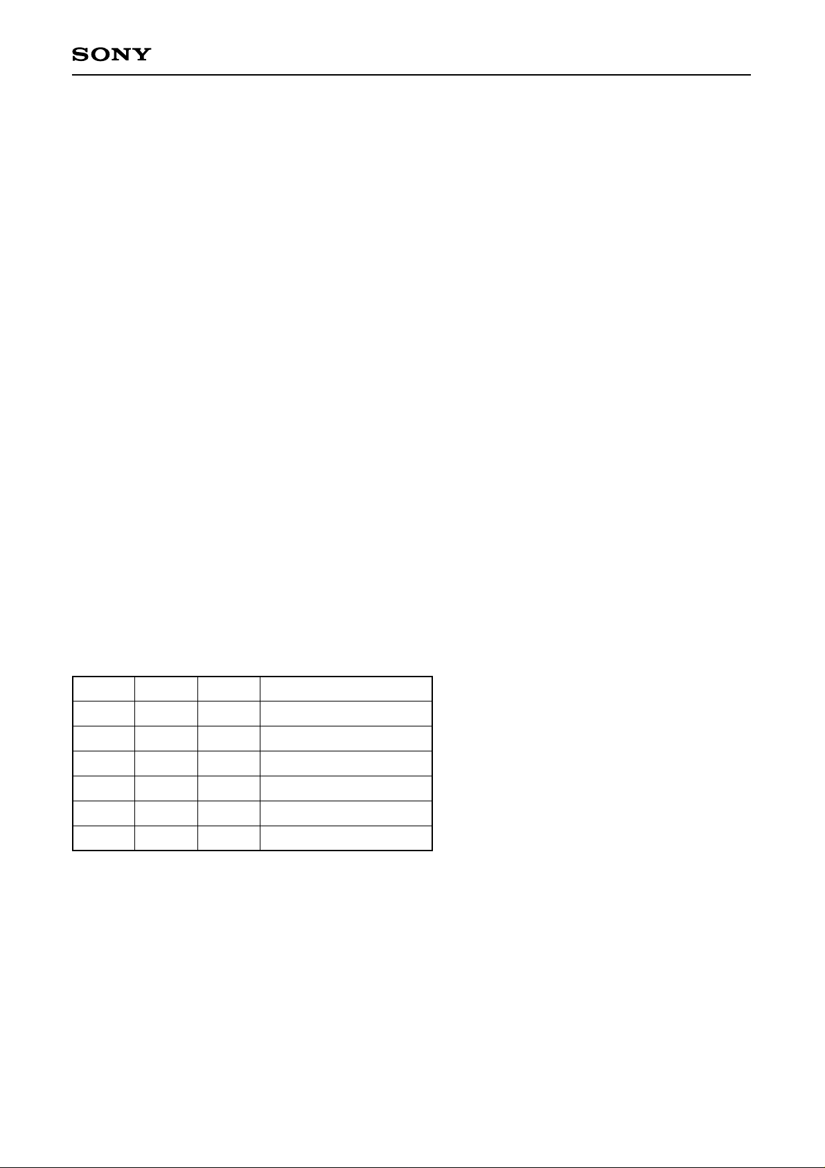
• The correction status can be monitored outside the LSI.
See Table 4-1.
• When the C2 pointer is high, the data in question was uncorrectable. Either the pre-value was held for that
data, or an average value interpolation was made.
MNT3
0
0
0
1
1
1
MNT1
0
0
1
0
0
1
MNT0
0
1
1
0
1
1
Table 4-1.
Description
No C1 errors
One C1 error corrected
C1 correction impossible
No C2 errors
One C2 error corrected
C2 correction impossible
– 45 –
Page 46
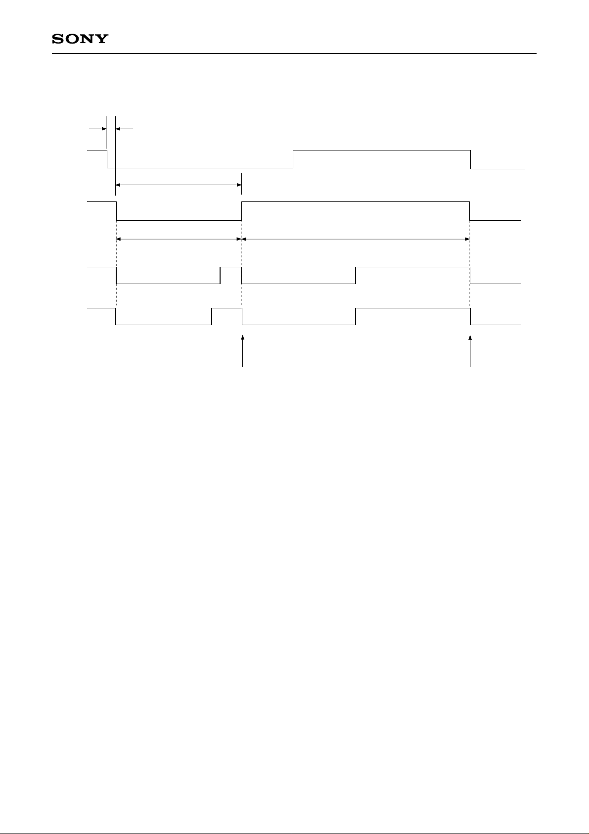
Timing Chart 4-1
Normal-speed PB
RFCK
MNT3
MNT1
MNT0
CXD2529Q
400 to 500ns
t = Dependent on error
condition
C1 correction C2 correction
Strobe
Strobe
4-4. DA Interface
• The CXD2529Q DA interface is as described below.
This interface includes 48 cycles of the bit clock within one LRCK cycle, and is MSB first. When LRCK is
high, the data is for the left channel.
– 46 –
Page 47
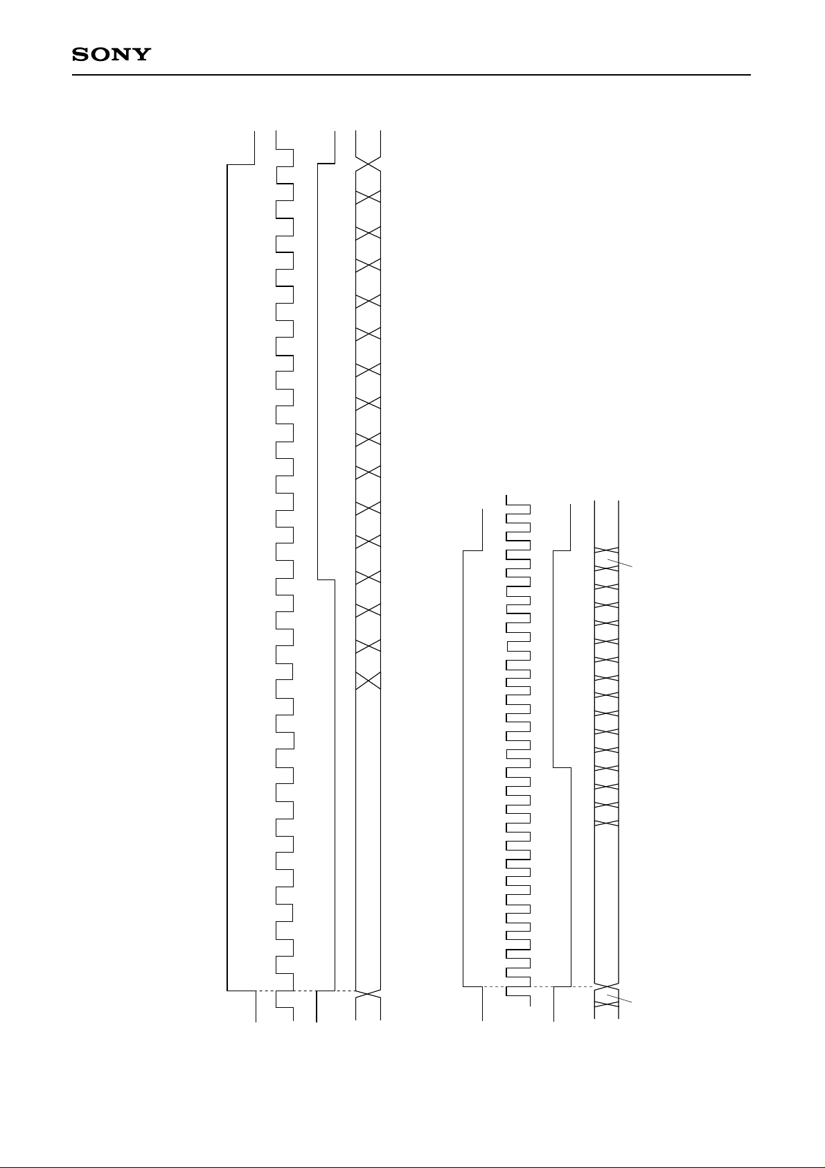
24
CXD2529Q
23456789101112
Rch MSB
24
L0
L14 L13 L12 L11 L10 L9 L8 L7 L6 L5 L4 L3 L2 L1 L0 RMSB
Lch MSB (15)
Lch MSB (15)
Timing Chart 4-2
1
48bit slot Normal-Speed Playback
LRCK
(44.1k)
BCK
(2.12M)
WDCK
R0
PCMD
12
48bit slot Double-Speed Playback
LRCK
(88.2k)
BCK
– 47 –
(4.23M)
WDCK
R0
PCMD
Page 48

CXD2529Q
4-5. Digital Out
There are three Digital Out formats: the type 1 format for broadcasting stations, the type 2 form 1 format for
home use, and the type 2 form 2 format for the manufacture of software.
The CXD2529Q supports type 2 form 1.
Sub Q data which are matched twice in succession after a CRC check are input to the first four bits (bit 0 to
3) of the channel status.
Digital Out C bit
0
12 3456 78 9101112131415
0
16
32
48
From sub Q
COPY
Emph
ID1
ID0
0 0 0 0 0 0 0 0 0 0 0 0 0 0/1 0 0
0 0 0 0 1 0 0 0 0 0 0 0
0
176
Bits 0 to 3... Sub Q control bits that matched twice with CRCOK
Bit 29 ... 1 when VPON is 1
Table 4-2.
4-6. Servo Auto Sequencer
This function performs a series of controls, including auto focus and track jumps. When the auto sequence
command is received from the CPU, auto focus, 1-track jump, 2N-track jumps, and N-track move are
executed automatically.
SSP (servo signal processor LSI) is used in an exclusive manner during the auto sequence execution (when
XBUSY = low), so that commands from the CPU are not transferred to the SSP, but can be sent to the
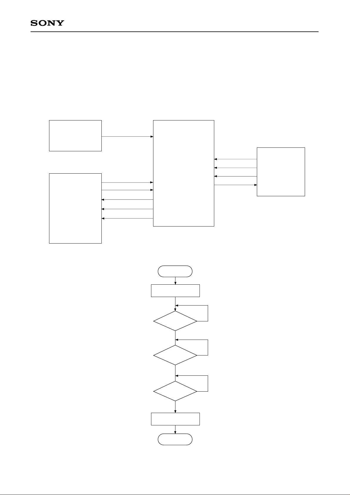
CXD2529Q.
Connect the CPU, RF and SSP as shown in Fig. 4-2.
When CLOK goes from low to high while XBUSY is low, XBUSY does not become high for a maximum of
100µs after that point. This is designed to prevent the transfer of erroneous data to the SSP when XBUSY
changes from low to high by the monostable multivibrator, which is reset by CLOK being low (when XBUSY
is low).
– 48 –
Page 49
CXD2529Q
(a) Auto Focus ($47)
Focus search-up is performed, FOK and FZC are checked, and the focus servo is turned on.
If $47 is received from the CPU, the focus servo is turned on according to Fig. 4-3. The auto focus starts with
focus search-up, and the pickup should be lowered beforehand (focus search-down). In addition, blind E of
register 5 is used to eliminate FZC chattering. In other words, the focus servo is turned on at the falling edge
of FZC after FZC has been continuously high for a longer time than E.
Connection diagram for using auto sequencer (example)
RF
SSP
FOK
C. out
SENS
DATA
CLK
XLT
FOK
CXD2529Q
CNIN
SEIN
DATO
CLKO
XLTO
Fig. 4-2.
Auto focus
Focus search up
DATA
CLOK
XLAT
SENS
Micro-computer
FOK = H
YES
FZC = H
YES
FZC = L
YES
Focus servo ON
END
NO
(Checks whether FZC is continuously high for
the period of time E set with register 5)
NO
NO
Fig. 4-3-(a). Auto Focus Flow Chart
– 49 –
Page 50
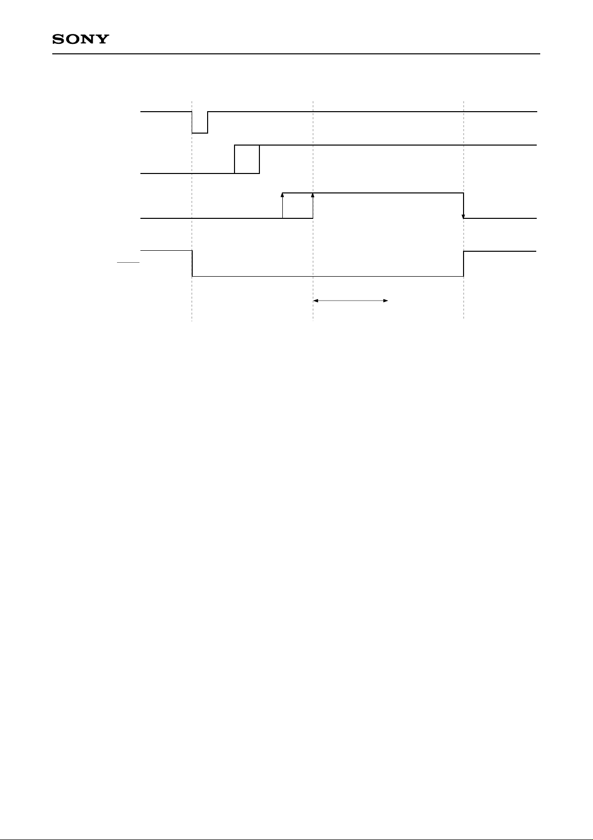
XLT
FOK
SEIN (FZC)
BUSY
Command for
SSP
$47latch
$03
CXD2529Q
Blind E
$08
Fig. 4-3-(b). Auto Focus Timing Chart
(b) Track Jump
1, 10, and 2N-track jumps are performed respectively. Always use this when focus, tracking, and the sled
servo are on. Note that tracking gain-up and braking-on should be sent beforehand because they are not
performed.
• 1-track jump
When $48 ($49 for REV) is received from the CPU, a FWD (REV) 1-track jump is performed in accordance
with Fig. 4-4. Set blind A and brake B with register 5.
• 10-track jump
When $4A ($4B for REV) is received from the CPU, a FWD (REV) 10-track jump is performed in accordance
with Fig. 4-5. The principal difference between the 10-track jump and the 1-track jump is whether to kick the
sled or not. In addition, after kicking the actuator, when 5 tracks have been counted through CNIN, the brake
is applied to the actuator. Then, when the actuator speed is found to have slowed up enough (determined by
the CNIN cycle becoming longer than the overflow C set in register 5), the tracking and sled servos are
turned on.
• 2N-track jump
When $4C ($4D for REV) is received from the CPU, a FWD (REV) 2N-track jump is performed in accordance
with Fig. 4-6. The track jump count “N” is set in register 7. Although N can be set to 216tracks, note that the
setting is actually limited by the actuator. CNIN is used for counting the number of jumps.
Although the 2N track jump basically follows the same sequence as the 10-track jump, the one difference is
that after the tracking servo is turned on, the sled continues to move only for “D”, set in register 6.
• N-track move
When $4E ($4F for REV) is received from the CPU, a FWD (REV) N-track move is performed in accordance
with Fig. 4-7. N can be set to a maximum of 216tracks. CNIN is used for counting the number of jumps. This
N-track move uses a method in which only the sled is moved, and is suited for moves over thousands of
tracks.
– 50 –
Page 51
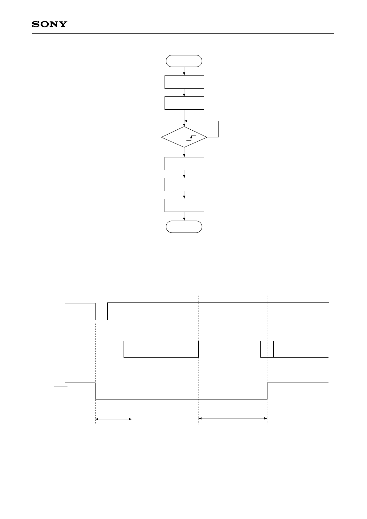
Track
CXD2529Q
Track FWD kick
sled servo OFF
WAIT
(Blind A)
CNIN =
YES
Track REV
kick
WAIT
(Brake B)
Track, sled
servo ON
END
(REV kick for REV jump)
NO
(FWD kick for REV jump)
Fig. 4-4-(a). 1-Track Jump Flow Chart
XLT
CNIN
BUSY
Command for
SSP
$48 (REV = $49) latch
Blind A
$28 ($2C)
Brake B
$2C ($28)
Fig. 4-4-(b). 1-Track Jump Timing Chart
$25
– 51 –
Page 52
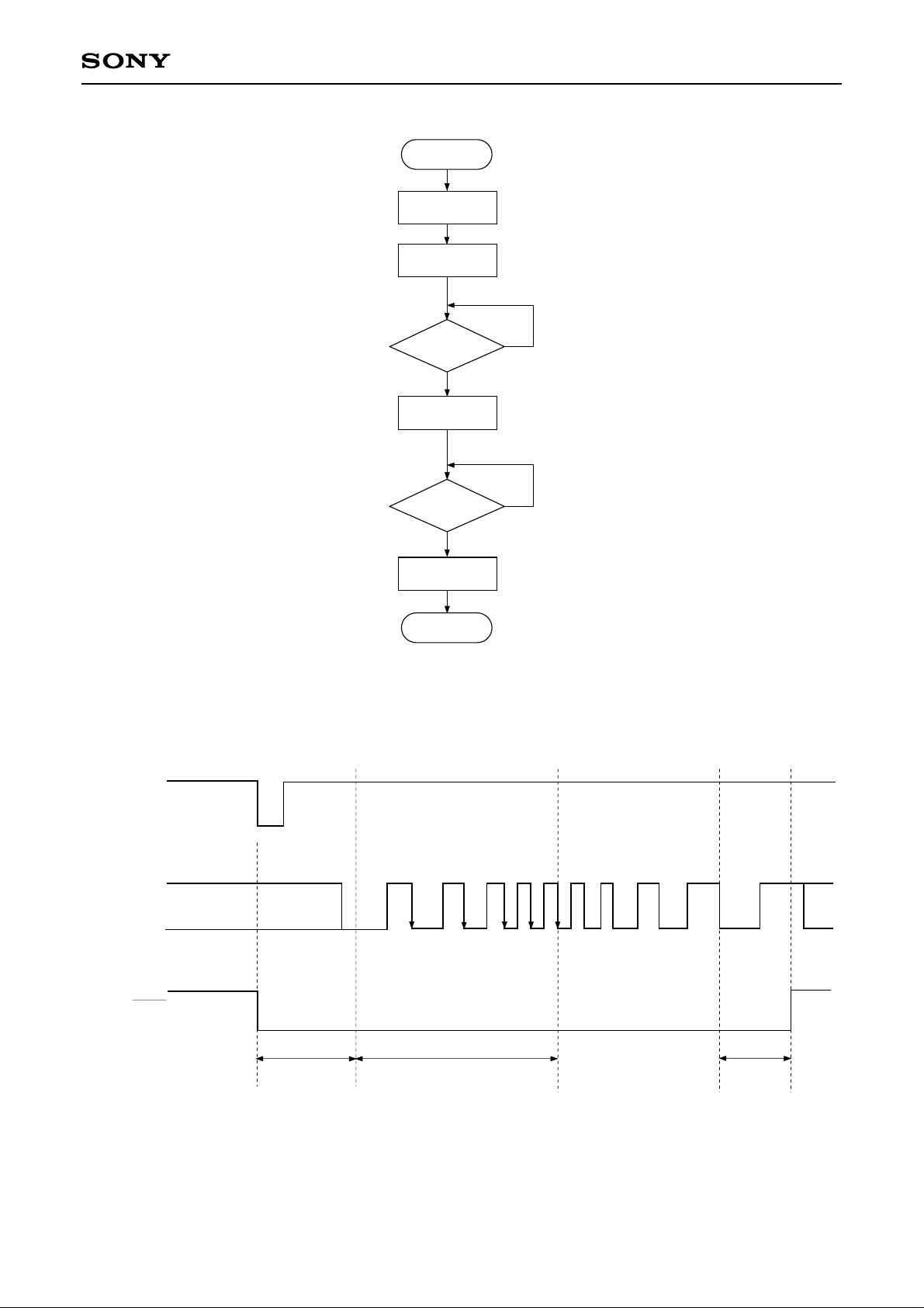
10 Track
Track, sled
FWD kick
CXD2529Q
WAIT
(Blind A)
CNIN = 5 ?
YES
Track, REV
kick
C = Overflow ?
YES
Track, sled
servo ON
END
(Counts CNIN × 5)
NO
NO
(Checks whether the CNIN cycle
is longer than overflow C)
Fig. 4-5-(a). 10-Track Jump Flow Chart
XLT
CNIN
BUSY
Command for
SSP
$4A (REV = $4B) latch
Blind A
$2A ($2F)
Fig. 4-5-(b). 10-Track Jump Timing Chart
CNIN 5 count
$2E ($2B)
Overflow C
$25
– 52 –
Page 53
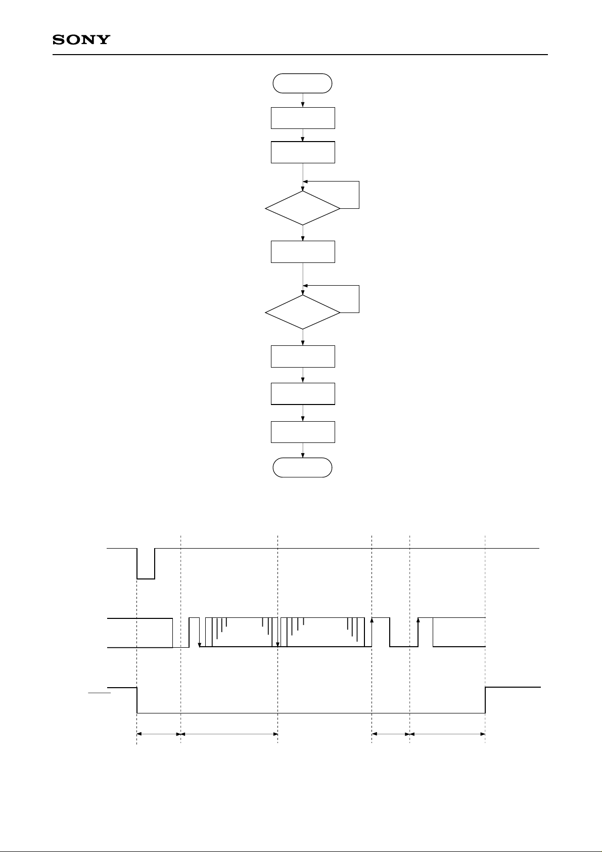
2N Track
Track, sled
FWD kick
WAIT
(Blind A)
CXD2529Q
CNIN = N
Track REV
kick
C = Overflow
Track servo
ON
WAIT
(Kick D)
Sled servo
ON
END
NO
YES
NO
YES
Fig. 4-6-(a). 2N-Track Jump Flow Chart
XLT
CNIN
BUSY
Command for
SSP
$4C (REV = $4D) latch
Blind A
$2A ($2F)
CNIN
N count
$2E ($2B)
Overflow
$26 ($27)
Fig. 4-6-(b). 2N-Track Jump Timing Chart
– 53 –
Kick D
$25
Page 54
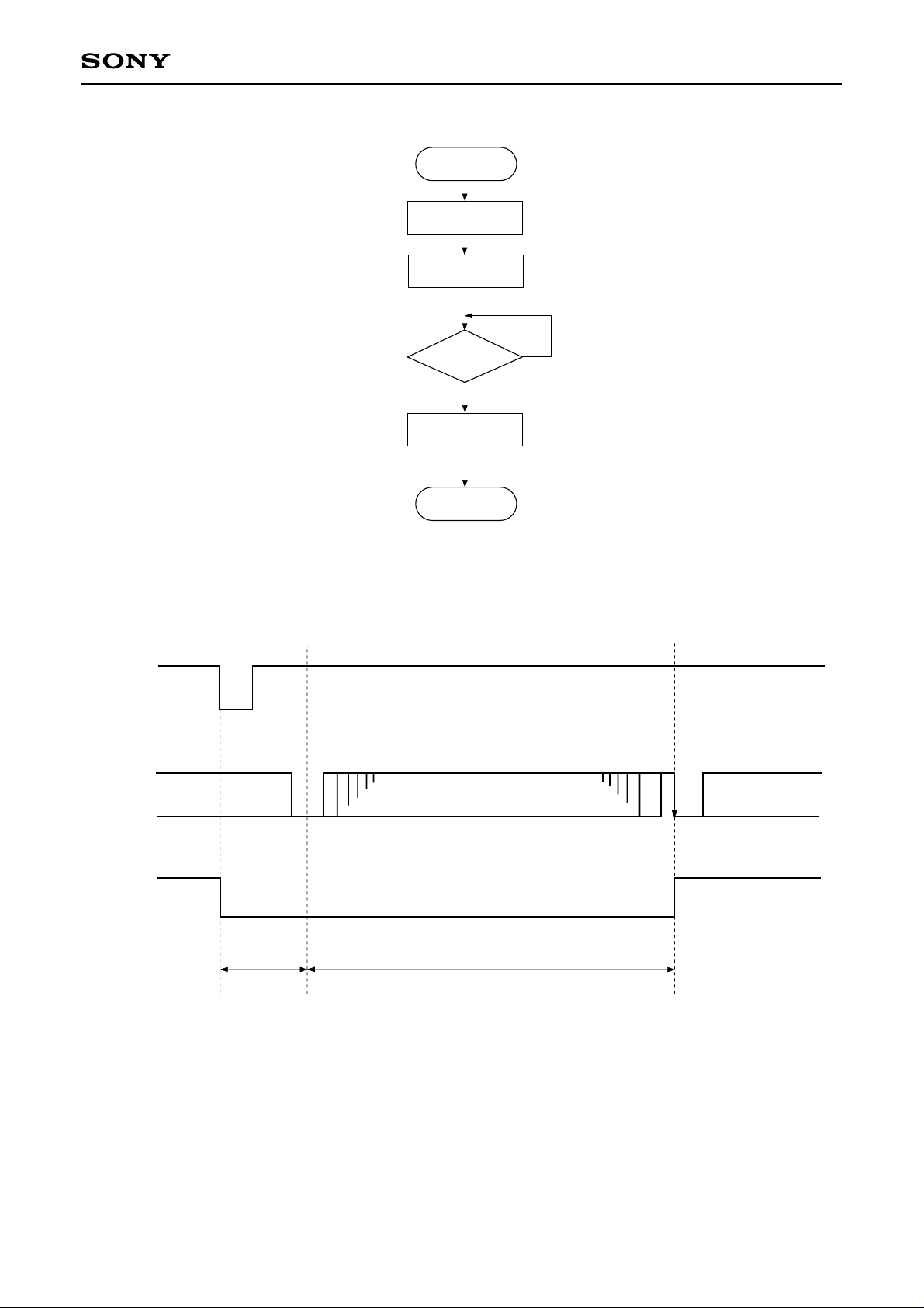
N Track move
Track servo OFF
Sled FWD kick
WAIT
(Blind A)
CXD2529Q
XLT
CNIN
$4E (REV = $4F) latch
CNIN = N
YES
Track, sled
servo OFF
END
END
NO
Fig. 4-7-(a). N-Track Move Flow Chart
BUSY
Command for
SSP
$22 ($23)
Blind A
CNIN N count
$20
Fig. 4-7-(b). N-Track Move Timing Chart
– 54 –
Page 55
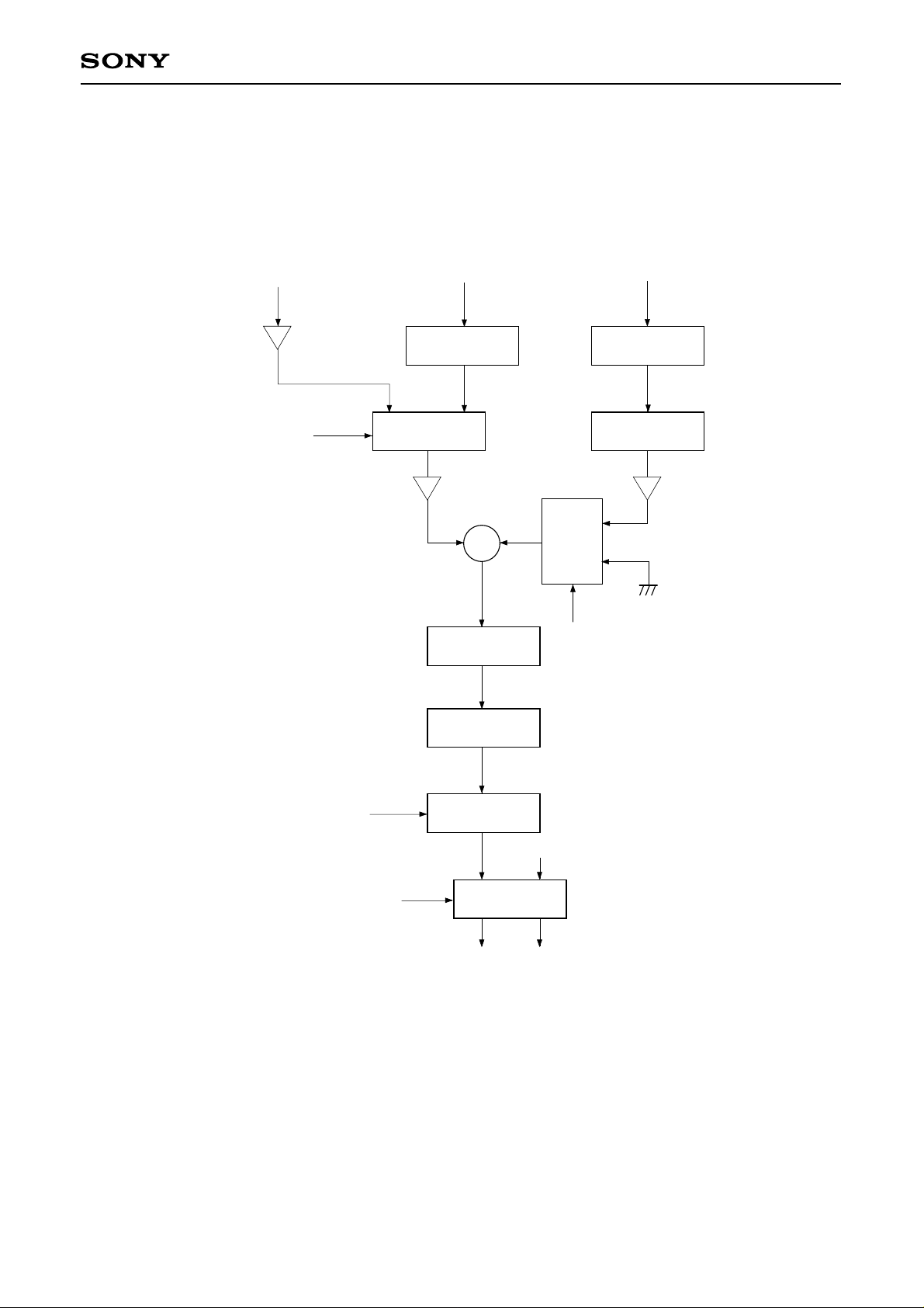
CXD2529Q
4-7. Digital CLV
Fig. 4-8 shows the Block Diagram. Digital CLV allows PWM output in CLVS, CLVP and other modes with the
MDS error and MDP error signal sampling frequency increased to 130kHz during normal-speed operation.
In addition, the digital spindle servo can set the gain.
Digital CLV
CLVS U/D
MDS Error
Measure Measure
MDP Error
CLV P/S
KICK, BRAKE, STOP
Gain
MDS
2/1 MUX
+
Over Sampling
Filter-2
Noise Shape
Modulation
Over Sampling
Filter-1
Gain
MDP
1/2
MUX
CLV P/S
PWMI
DCLVMD, LPWR
CLVS U/D: Up/down signal from the CLVS servo
MDS error: Frequency error for CLVP servo
MDP error: Phase error for CLVP servo
PWMI: Spindle drive signal from the microcomputer
Mode Select
MDS
MDP
Fig. 4-8. Block Diagram
– 55 –
Page 56
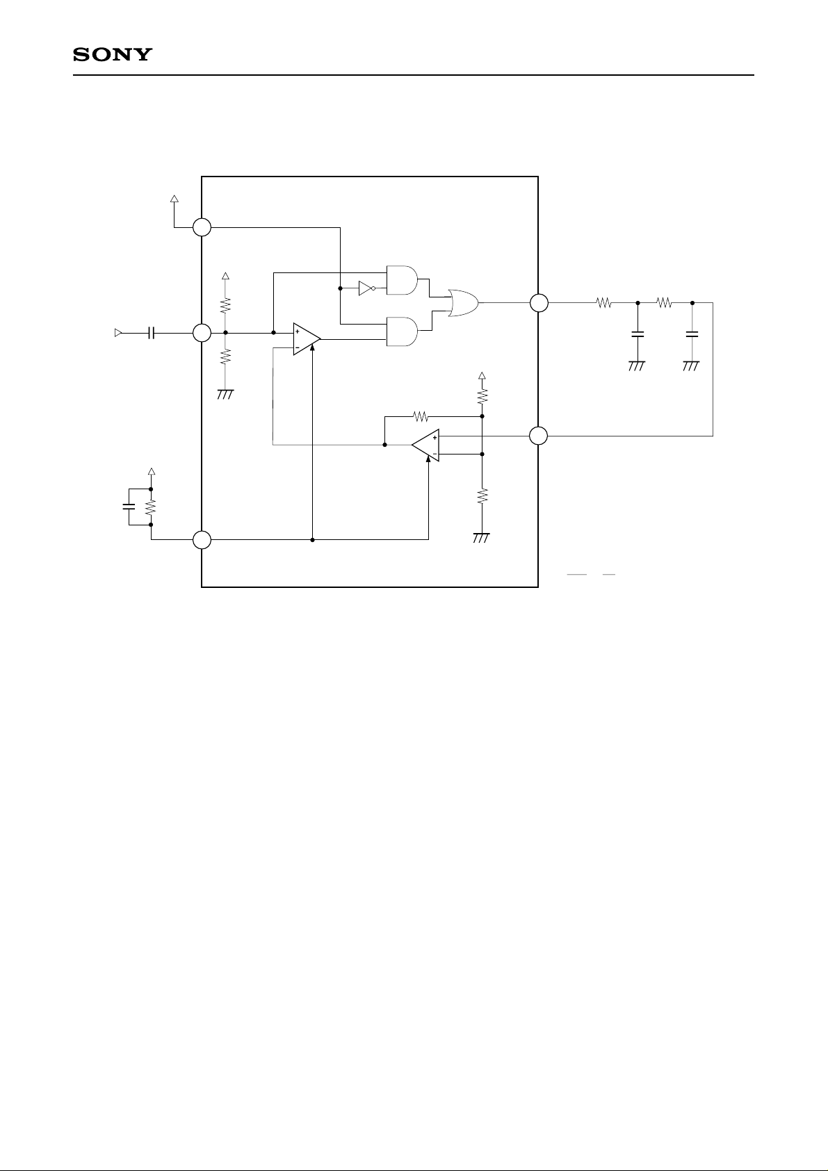
4-8. Asymmetry Compensation
48
ASYE
R1
RF
44
R1
CXD2529Q
CXD2529Q
ASYO
47
R1
R1
46
ASYI
BIAS
R2
45
Fig. 4-9. Example of Asymmetry Compensation Application Circuit
R1 2
=
R2 5
– 56 –
Page 57
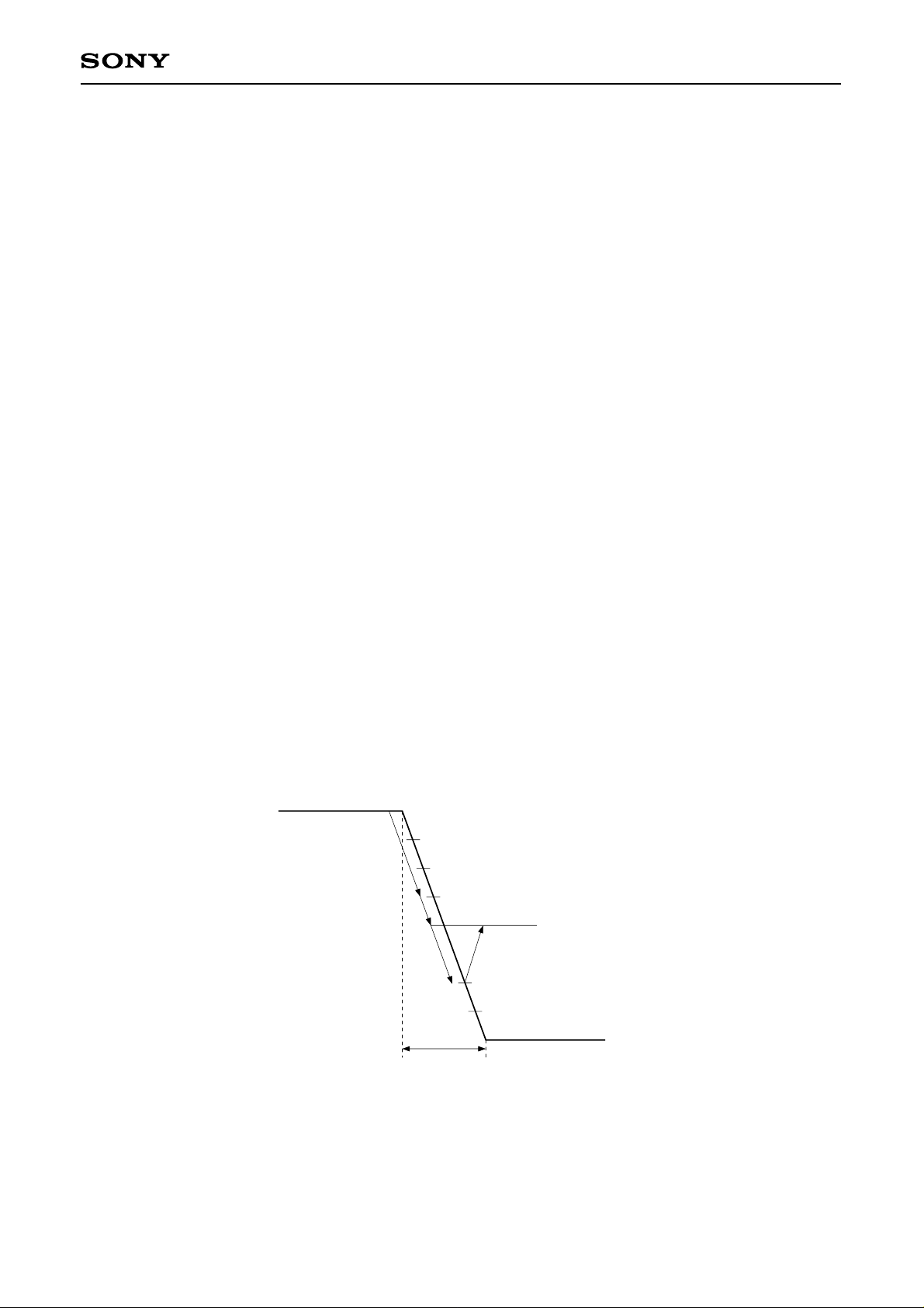
CXD2529Q
5. 1-bit DAC Block
5-1. DAC Block Input Timing
Fig. 5-1 shows the input timing for the DAC block.
In the CXD2529Q, there is no internal transfer of audio data from the CD signal processing block to the DAC
block. Therefore, data can be transferred to the DAC block through an audio DSP or similar device.
When data is input to the DAC block without passing through an audio DSP or similar device, data should be
connected externally. In this case, EMPH, LRCK, BCK and PCMD can be connected directly with EMPHI,
LRCKI, BCKI and PCMDI respectively.
5-2. Description of DAC Block Functions
Zero Data Detection
When the condition where the lower 4 bits of the input data are DC and the remaining upper bits are all “0” or
all “1” continues for approximately 300ms, zero data is detected. Zero data detection is performed
independently for the left and right channels.
Mute Flag Output
The LMUT and RMUT pins become active when any of the following conditions are met.
The polarity can be selected by the $9X command ZDPL.
• When zero data is detected.
• When a high signal is input to the SYSM pin.
• When the $AX command SMUT is set.
Attenuation Operation
Assume attenuation data X1, X2, and X3, where X1 > X3 > X2, and audio outputs Y1, Y2, and Y3, where Y1 >
Y3 > Y2. First, assume X1 is transferred and then X2 is transferred. If X2 is transferred before Y1 is reached
(state “A” in the diagram), then the value continues approaching Y2. Next, if X3 is transferred before Y2 is
reached (either state “B” or “C”), the value begins approaching Y3 from the value at that point (“B” or “C”).
0dB
7F (H)
A
Y1
B
Y3
C
Y2
– ∞
23.2 [ms]
00 (H)
– 57 –
Page 58
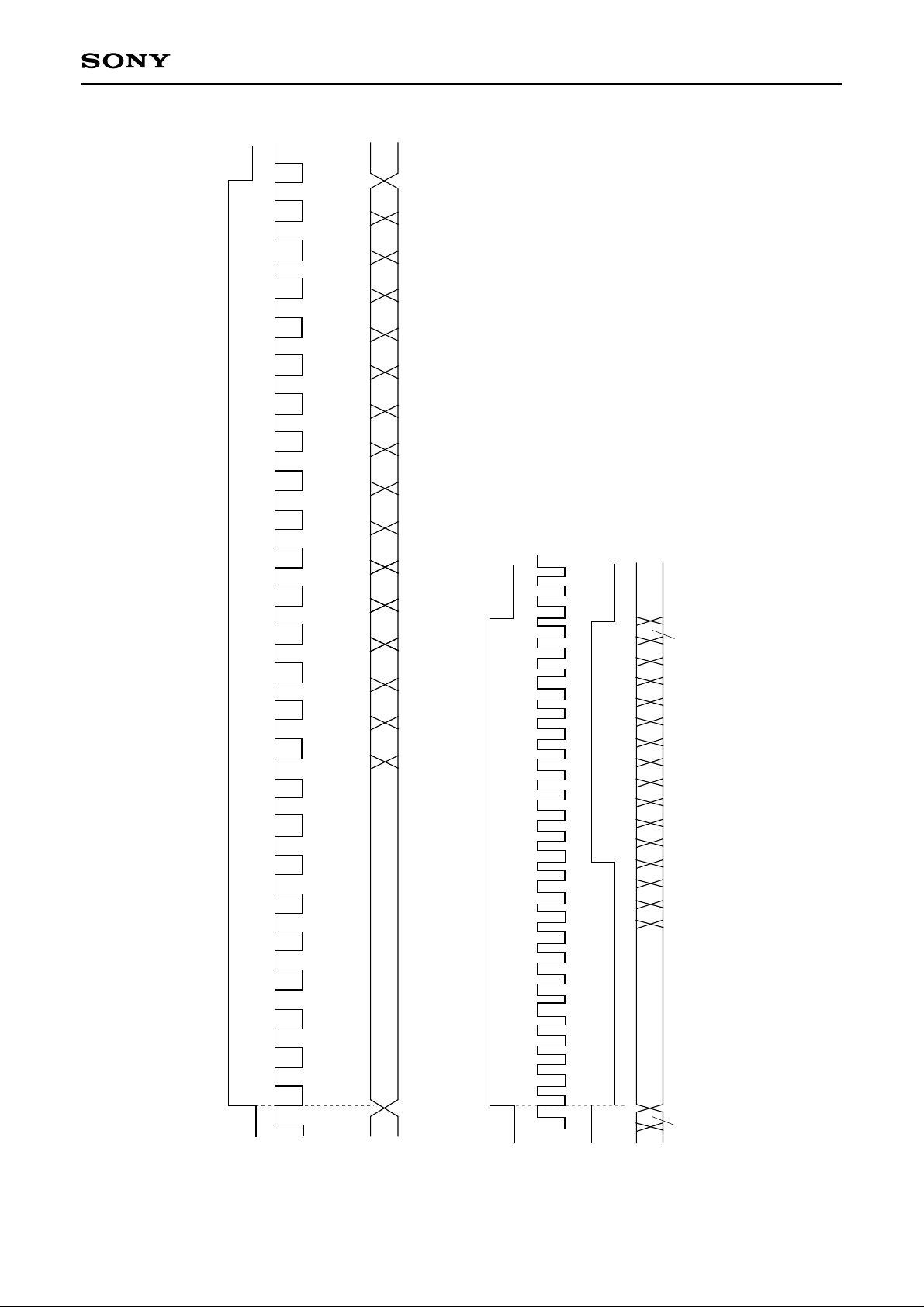
24
CXD2529Q
L6 L5 L4 L3 L2 L1 L0 RMSB
23456789101112
1
Rch MSB
24
L0
L14 L13 L12 L11 L10 L9 L8 L7
Input Timing for DAC Block
Lch MSB (15)
Lch MSB (15)
2
1
Timing Chart 5-1
BCKI
LRCKI
(44.1k)
Normal-Speed Playback
(2.12M)
R0
PCMDI
LRCKI
Double-Speed Playback
(88.2k)
– 58 –
BCKI
(4.23M)
R0
PCMDI
Page 59
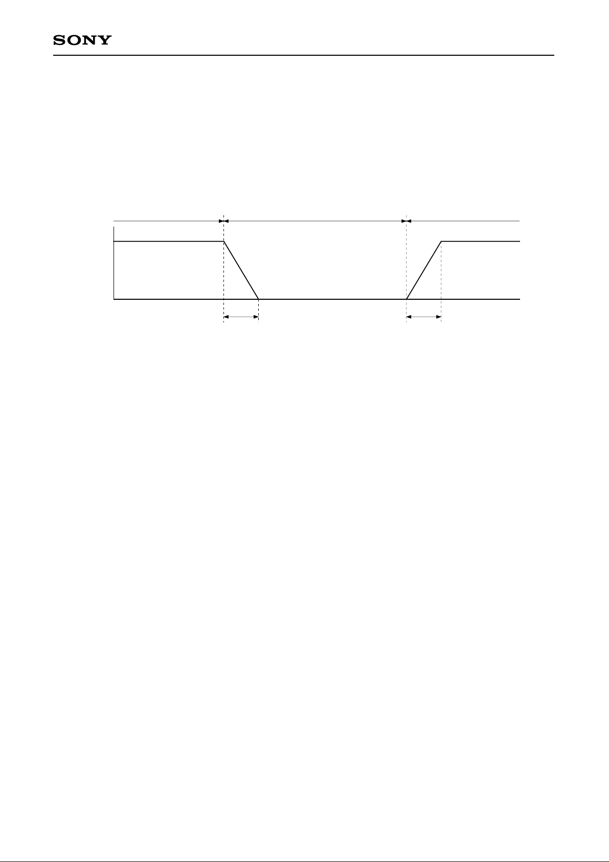
CXD2529Q
DAC Block Mute Operation
Soft mute
Soft mute is applied when any of the following conditions are met. Mute is performed, attenuating the input
data.
• When attenuation data is set to 000 (h)
• When the $AX command SMUT is set to 1
• When a high signal is input to the SYSM pin
Soft mute on Soft mute offSoft mute off
0dB
–∞dB
23.2 [ms] 23.2 [ms]
Forced mute
Forced mute is applied when the $AX command FMUT is set to 1.
The PWM output to the LPF block is fixed to low.
∗
Set OPSL2 to 1 for FMUT setting. (See the description of “$AX commands”.)
Zero detection mute
Forced mute is applied when the $9X command ZMUT is set to 1 and the zero data is detected for the left
and right channels.
(See the description of “Zero Data Detection”.)
LRCK Synchronization
Synchronization is performed at the first LRCK input falling edge during reset. When the LRCK input
frequency varies, the synchronization is lost. At that time, resynchronization should be executed.
The LRCK input frequency varies to the IC master clock switching and playback speed change when the
high/low levels of the XTSL pin change, $9 command DSPB setting changes or $9X command MCSL setting
changes.
Also, LRCK may be switched when there is another IC between the CD DSP block and DAC block. In this
case resynchronization is required.
In order to perform resynchronization, set the $AX command LRCK to 1 and set LRWO to 0 after one LRCK
cycle or more.
∗
Set LRWO with OPSL2 = 1. (See the description of “$AX commands”.)
∗
Set the $9X command SYCOF = 0 in advance when setting LRWO to 1.
– 59 –
Page 60
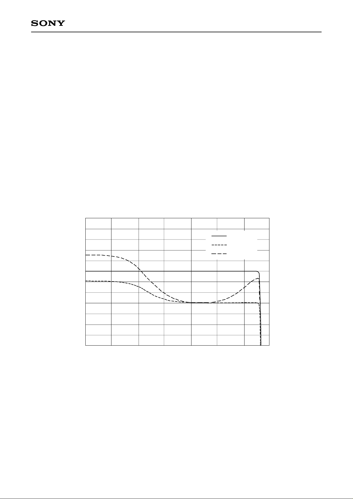
CXD2529Q
SYCOF
Playback can be simply performed by setting SYCOF of address 9 to 1 when LRCK is connected to LRCKI,
PCMD to PCMDI and BCK to BCK in CAV-W mode.
Normally, the memory proof and the like is used for playback in CAV-W mode.
In this mode, the LRCK output conforms not to the crystal but to the VCO. Therefore, synchronization is
frequently lost.
By setting SYCOF of address 9 to 1, the synchronization loss of the LRCKI input is ignored and the
playback can be simply performed.
However, the playback is not perfect because the pre-value hold or data skip is occurred for the LRCKI input
wow flatter.
∗
Set SYCOF to 0 in all cases except for the playback with LRCK directly connected to LRCKI,
PCMD to PCMDI and BCK to BCK in CAV-W mode.
∗
Set SYCOF to 0 in advance when LRCK resynchronization is applied with LRWO = 0.
Digital Bass Boost
Bass boost without the external parts is possible by the built-in digital filter. The strength of boost has 2
levels; Mid and Max. BSBST and BBSL of address A are used for the setting.
See Graph 5-2 for the digital bass boost frequency response.
[dB]
10.00
8.00
6.00
4.00
2.00
0.00
–2.00
–4.00
–6.00
–8.00
–10.00
–12.00
–14.00
10 30 100 300 1k 3k 10k 30k
Digital Bass Boost Frequency Response [Hz]
Normal
DBB Mid
DBB Max
Graph 5-2.
– 60 –
Page 61
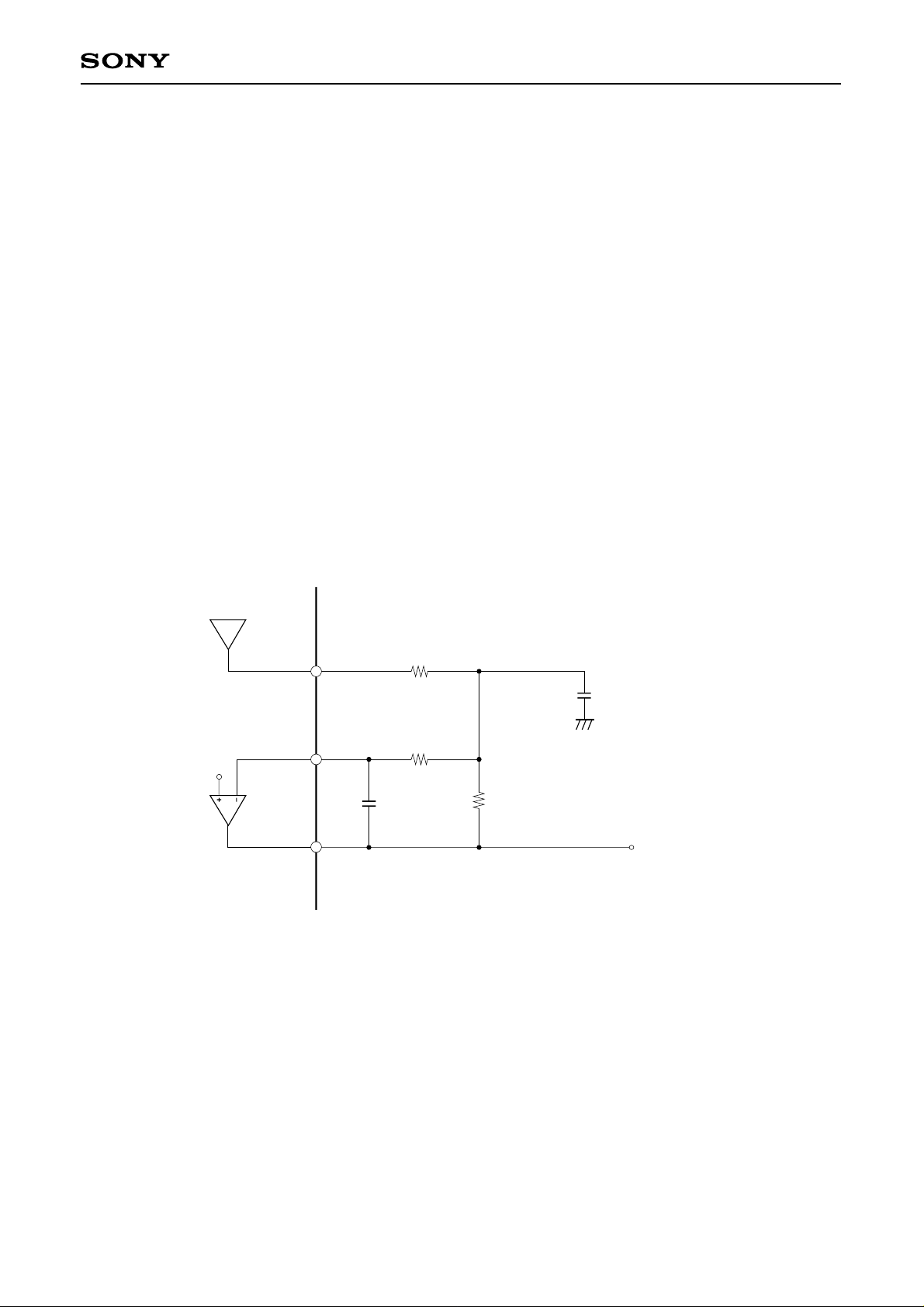
CXD2529Q
6. LPF Block
The CXD2529Q incorporates a first-stage secondary active LPF and a reference voltage-applied operational
amplifier, which require many resistors and capacitors.
The cut-off frequency fc can be freely set due to the external resistors and capacitors.
Here, the reference voltage (Vc) is (AVDD – AVSS)/2.
Fig. 6-1 shows the LPF block application circuit.
In this circuit, the cut-off frequency is fc ≈ 40kHz.
The external capacitors’ values when fc = 30kHz and 50kHz are indicated below for reference.
The resistors’ values do not change.
• When fc ≈ 30kHz:
C1 = 200pF, C2 = 910pF
• When fc ≈ 50kHz:
C1 = 120pF, C2 = 560pF
LPF Block Application Circuit
AOUT1 (2)
AIN1 (2)
Vc
LOUT1 (2)
12k
12k
C1
150p
12k
Fig. 6-1. LPF External Circuit Example
C2
680p
Analog out
– 61 –
Page 62
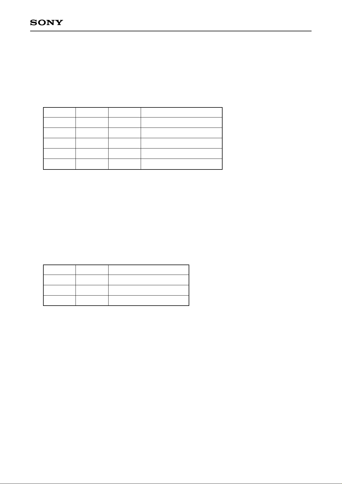
CXD2529Q
7. Setting Method of the CXD2529Q Playback Speed (in CLV-N mode)
(A) CD-DSP block
The playback modes shown below can be selected by the combination of the crystal, XTSL pin and $9X
command DSPB.
CD-DSP block playback speed
Crystal
768Fs
768Fs
384Fs
384Fs
384Fs
XTSL DSPB CD-DSP block playback speed
1
1
0
0
1
0
1
0
1
1
× 1
× 2
× 1
× 2
× 1
∗1
Fs = 44.1kHz
∗1
Low power consumption mode. The CD-DSP processing speed is halved, allowing the power
consumption to be decreased.
(B) 1-bit DAC block
The operating speed of the DAC block is determined by the crystal and the $9X command MCSL
regardless of the operating conditions of the CD-DSP block mentioned above. This allows the playback
mode for the DAC block and CD-DSP block to be set independently.
1-bit DAC block playback speed
Crystal
MCSL DAC block playback speed
768Fs
768Fs
384Fs
Fs = 44.1kHz
1
0
0
× 1
× 2
× 1
– 62 –
Page 63
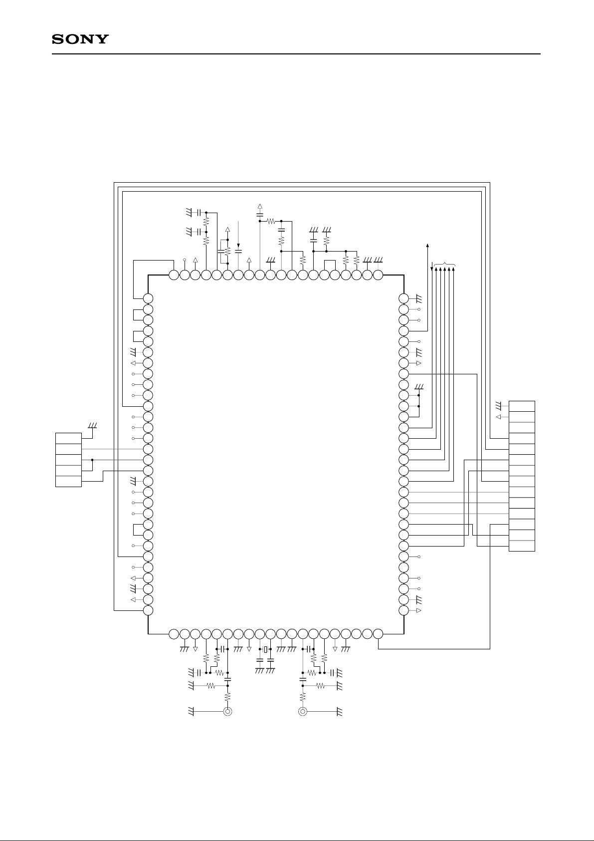
RF
DRIVER
LS
CXD2529Q
SSP
GND
MNT3
MNT2
MNT1
MNT0
49
50
LRCKI
LRCK
51
52
53
54
55
56
57
58
59
60
61
62
63
64
65
66
67
68
69
70
71
72
73
74
75
76
77
78
79
80
WDCK
PCMD
PCMDI
BCK
BCKI
V
SS
V
DD
GTOP
XUGF
XPCK
GFS
RFCK
C2PO
XROF
MNT3
MNT1
MNT0
XTSL
FSTT
C4M
DOUT
EMPH
EMPHI
WFCK
SCOR
SBSO
EXCK
V
SS
V
DD
SYSM
NC
AVSSAVDD
81
82
48
ASYE
83
46
47
ASYI
ASYO
AOUT1
AIN1
84
85
45
44
RF
BIAS
LOUT1
AVSSXTAI
87
86
DD
AV
DD
XV
43
42
41
SS
AV
CLTV
XTAO
89
90
88
40
FILI
XVSSAVSS
91
39
FILO
92
38
PCO
VCTL
LOUT2
AIN2
93
37
94
34
36
35
VCKI
V16M
VPCO1
AOUT2
AVDDAVSSNCNC
95
96
97
33
32
TES1
VPCO2
98
99
31
TES0
XRST
100
PWMI
LOCK
MDS
MDP
MON
V
SS
V
DD
FOK
XLON
SPOD
SPOC
SPOB
SPOA
CLKO
XLTO
DATO
CNIN
SEIN
CLOK
XLAT
DATA
SENS
SQSO
SQCK
CKOUT
TES2
RMUT
LMUT
V
SS
V
DD
30
29
27 28
26
25
24
23
22
21
20
19
18
17
16
15
14
13
12
11
10
9
8
7
Application circuits shown are typical examples illustrating the operation of the
devices. Sony cannot assume responsibility for any problems arising out of the use of
these circuits or for any infringement of third party patent and other right due to same.
V
SS
V
DD
MUTE
SCOR
SQCK
SQSO
GFS
CLK
XLAT
DATA
XRST
SENS
FOK
6
5
4
3
2
1
Application Circuit
– 63 –
Page 64
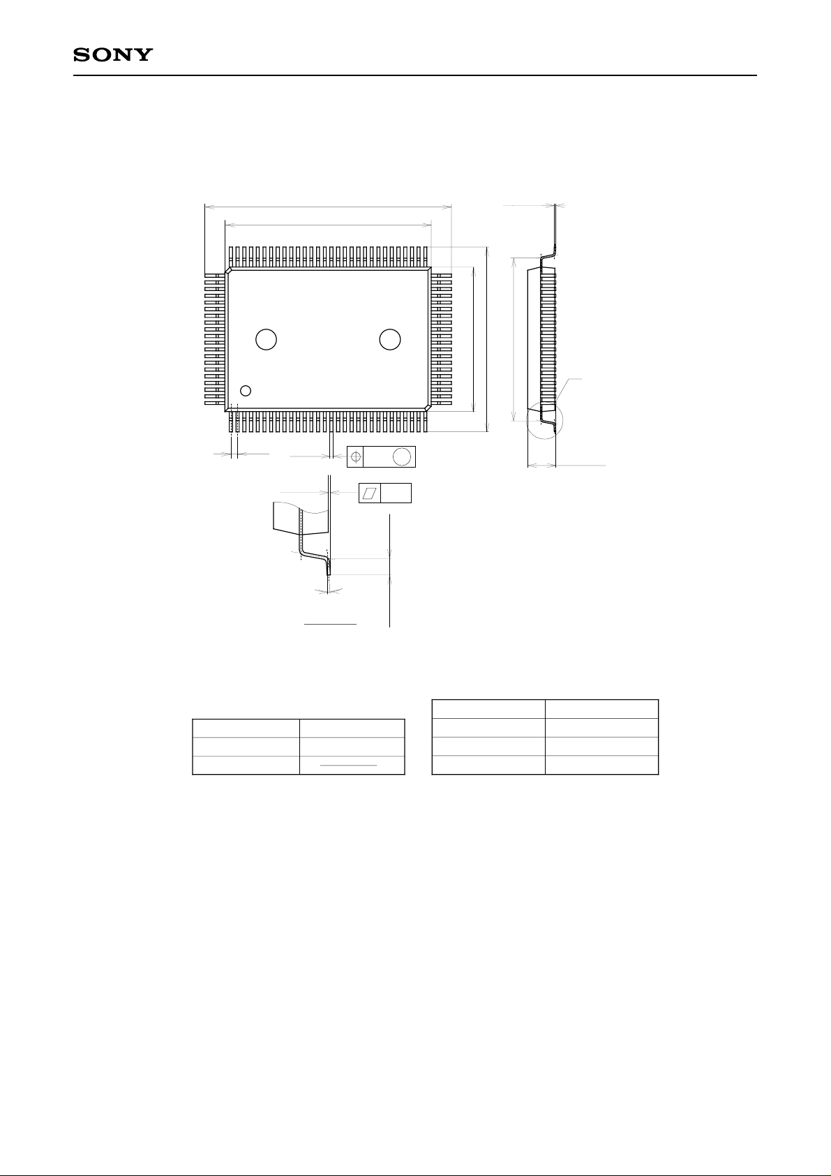
Package Outline Unit: mm
100PIN QFP (PLASTIC)
23.9 ± 0.4
+ 0.4
20.0 – 0.1
+ 0.4
17.9 ± 0.4
14.0 – 0.01
+ 0.1
0.15 – 0.05
15.8 ± 0.4
CXD2529Q
A
SONY CODE
EIAJ CODE
JEDEC CODE
0.65
0° to 15°
±0.12
DETAIL A
QFP-100P-L01
∗QFP100-P-1420-A
M
0.15
(16.3)
0.8 ± 0.2
2.75 – 0.15
PACKAGE STRUCTURE
PACKAGE MATERIAL
LEAD TREATMENT
LEAD MATERIAL
PACKAGE WEIGHT
EPOXY RESIN
SOLDER PLATING
COPPER / 42 ALLOY
1.4g
+ 0.35
– 64 –
 Loading...