

Page 1

—1—
E91Z07G86-TE
Sony reserves the right to change products and specifications without prior notice. This information does not convey any license by
any implication or otherwise under any patents or other right. Application circuits shown, if any, are typical examples illustrating the
operation of the devices. Sony cannot assume responsibility for any problems arising out of the use of these circuits.
Absolute Maximum Ratings (Ta=25 °C)
• Supply voltage VDD 7V
• Reference voltage
VRT, VRB VDD + 0.5 to VSS – 0.5 V
• Input voltage VIN VDD + 0.5 to VSS – 0.5 V
(Analog)
• Input voltage VI VDD + 0.5 to VSS – 0.5 V
(Digital)
• Output voltage VO VDD + 0.5 to VSS – 0.5 V
(Digital)
• Storage temperature
Tstg –55 to +150 °C
Recommended Operating Conditions
• Supply voltage AVDD, AVSS 4.75 to 5.25 V
DVDD, DVSS
| DVSS – AVSS | 0 to 100 mV
• Reference input voltage
VRB 0 and above V
VRT 2.7 and below V
• Analog input VIN 1.8 Vp-p above
• Clock pulse width
Tpw1, Tpw0 13 ns (min) to 1.1 µs (max)
• Operating ambient temperature
Topr –40 to +85 °C
Description
The CXD1179Q is an 8-bit CMOS A/D converter
for video with synchronizing clamp function. The
adoption of 2 step-parallel method achieves ultra-low
power consumption and a maximum conversion
speed of 35MSPS.
Features
• Resolution: 8-bit ± 1/2LSB (DL)
• Maximum sampling frequency: 35MSPS
• Low power consumption: 80 mW (at 35MSPS typ.)
(reference current excluded)
• Synchronizing clamp function
• Clamp ON/OFF function
• Reference voltage self bias circuit
• Input CMOS compatible
• 3-state TTL compatible output
• Single 5V power supply
• Low input capacitance: 8 pF
• Reference impedance: 330 Ω (typ.)
Applications
Wide range of applications that require high-speed
A/D conversion such as TV and VCR.
Structure
Silicon gate CMOS IC
8-bit 35MSPS Video A/D Converter with Clamp Function
32 pin QFP (Plastic)
CXD1179Q
Page 2

—2—
CXD1179Q
Block Diagram
2
3
4
5
6
7
8
10
11
12
9
30
31
32
1
Clock generator
Upper
data
latch
Lower
data
latch
Lower encoder
(4 BIT)
Lower encoder
(4 BIT)
Upper encoder
(4 BIT)
Lower sampling
comparator (4 BIT)
Lower sampling
comparator (4 BIT)
Upper sampling
comparator (4 BIT)
Reference supply
26
27
29
28
25
24
23
22
21
20
19
18
17
16
15
14
13
DVss
CCP VREF
CLE
VRBS
VRB
AVss
AVss
V
IN
AVDD
AVDD
VRTS
AV
DD
CLP
TEST
(V
DD or Vss)
TEST
(V
DD or Vss)
NC
TEST (OPEN)
CLK
TEST (DV
DD)
DV
DD
D7 (MSB)
D6
D5
D4
D3
D2
D1
D0 (LSB)
DVss
OE
VRT
Page 3

—3—
CXD1179Q
Pin Description
Pin No. Symbol Equivalent circuit Description
1 to 8
D0 to D7
TEST
CLK
TEST
D0(LSB) to D7 (MSB) output
Leave open during normal usage.
Clock input
Fix Pin 11 to VDD, Pins 13 and 14 to
VDD or VSS during normal usage.
9
12
11, 13, 14
Di
9
DV
DD
DVSS
12
DV
DD
DVSS
11
13
14
DV
DD
DVSS
10
DVDD
Digital +5 V
Page 4

—4—
CXD1179Q
15
CLP
18
VRT
24
VRB
21 VIN
25 VRBS
17
VRTS
Inputs clamp pulse to Pin 15 (CLP).
Clamps the signal voltage during Low
interval.
Generates about +2.6 V when shorted
with VRT.
Reference voltage (top)
Reference voltage (bottom)
Analog input
Generates about +0.6 V when shorted
with VRB.
Pin No. Symbol
Equivalent circuit Description
22, 23
AVSS
16, 19, 20 AVDD
15
DV
DD
DVSS
17
AV
DD
18
24
AV
DD
AVSS
21
AV
DD
AVSS
25
AV
SS
Analog +5 V
Analog ground
Page 5

—5—
CXD1179Q
Pin No. Symbol Equivalent circuit Description
26 VREF
CCP
CLE
OE
Clamp reference voltage input.
Clamps so that the reference voltage
and the input signal during clamp
interval are equal.
Integrates the clamp control voltage.
The relationship between the changes
in CCP voltage and in VIN voltage is
positive phase.
The clamp function is enabled when
CLE = Low.
The clamp function is set to off and
the converter functions as a normal
A/D converter when CLE = High.
The clamp pulse can be measured by
connecting CLE to DVDD through a
several hundred Ω resistor.
Data is output when OE = Low.
Pins D0 to D7 are at high impedance
when OE = High.
27
29
30
26
AV
DD
AVSS
AVDD
AVSS
27
DVDD
DVSS
29
CLAMP
PULSE
30
DV
DD
DVSS
28, 31
DVSS
Digital ground
32
NC
NC pin
Page 6
—6—
CXD1179Q
Digital Output
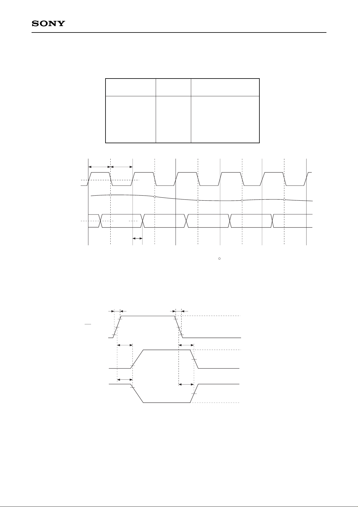
The following table shows the relationship between analog input voltage and digital output code.
tr = 4.5ns tf = 4.5ns
2.5V
tPLZ
tPHZ
10%
90%
tPZH
1.3V
1.3V
tPZL
10%
90%
OE input
output 1
5V
0V
V
OH
VOL (≠ DVSS)
V
OH (≠ DVDD)
V
OL
output 2
Input signal
voltage
Step
Digital output code
MSB LSB
VRT
:
:
:
:
VRB
0
:
127
128
:
255
1 1 1 1 1 1 1 1
:
1 0 0 0 0 0 0 0
0 1 1 1 1 1 1 1
:
0 0 0 0 0 0 0 0
Timing Chart I.
Timing Chart II.
Clock 2V
Analog input
Data output 2V
TPW1 TPW0
N
N – 3 N – 2 N – 1 N N + 1
Td = 13ns
N + 1
N + 2
N + 3
: Analog signal sampling point
N + 4
Page 7
—7—
CXD1179Q
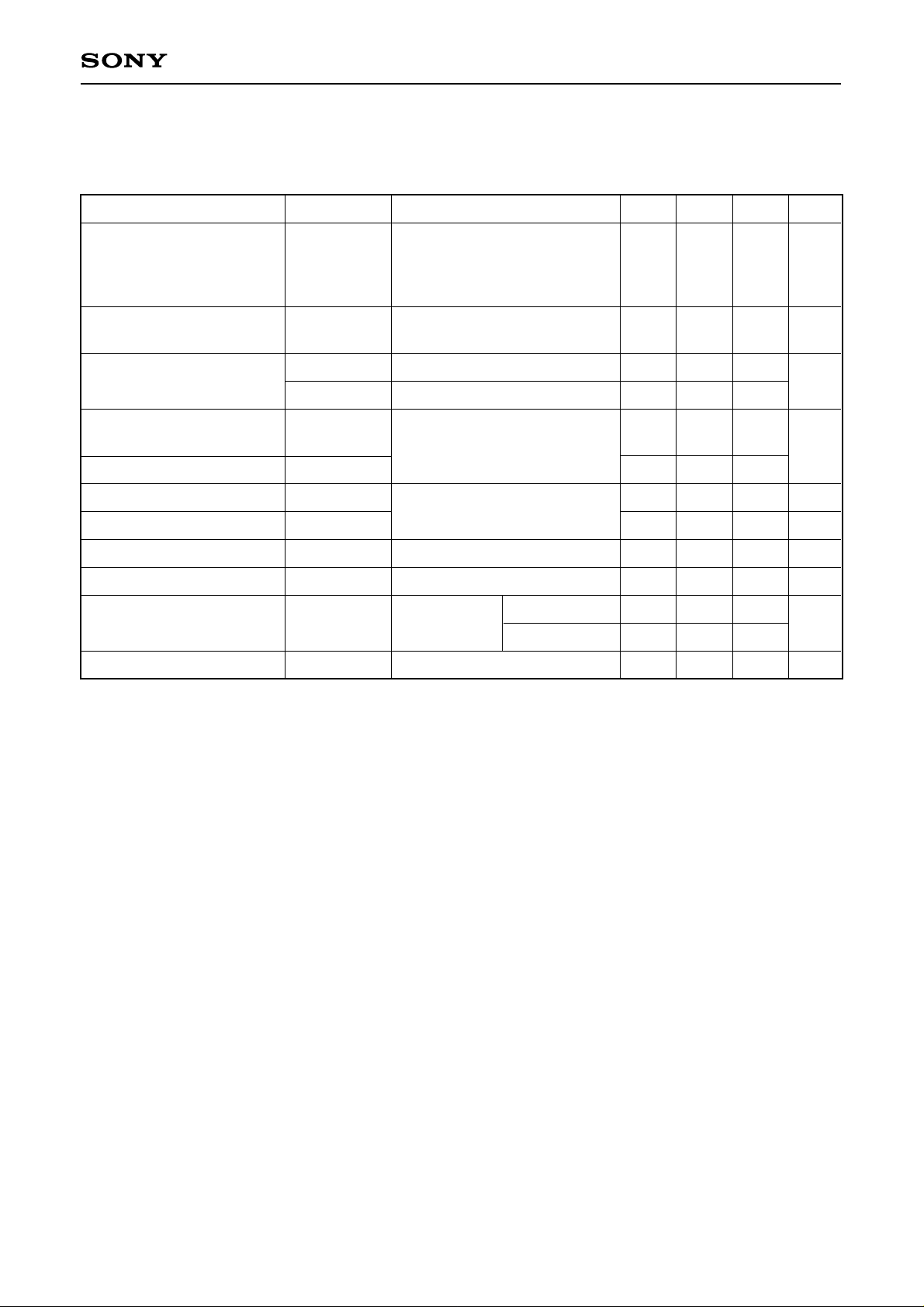
Electrical Characteristics
Analog characteristics (Fc = 35MSPS, VDD = 5 V, VRB = 0.5 V, VRT = 2.5 V, Ta = 25 °C)
Conversion speed
Analog input band width
(–1 dB)
Offset voltage
∗1
Integral non-linearity error
Differential non-linearity erro
r
Differential gain error
Differential phase error
Aperture jitter
Sampling delay
Clamp offset voltage
∗2
Clamp pulse delay
Fc
BW
EOT
EOB
EL
ED
DG
DP
taj
tsd
Eoc
tcpd
0.5
–60
+55
–20
–30
VDD = 4.75 to 5.25 V
Ta = –40 to +85 °C
VIN = 0.5 to 2.5 V
fIN = 1 kHz ramp
Envelope
Potential difference to VRT
Potential difference to VRB
End point
NTSC 40 IRE mod ramp
Fc = 14.3MSPS
VIN = DC,
PWS = 3 µs
25
–40
+75
+0.5
±0.3
1
0.5
30
2
0
–10
25
35
–20
+95
+1.3
–1.0
±0.5
+20
+10
MSPS
MHz
mV
LSB
%
deg
ps
ns
mV
ns
Item Symbol Conditions Min. Typ. Max. Unit
VREF = 0.5 V
VREF = 2.5 V
∗1
The offset voltage EOB is a potential difference between VRB and a point of position where the voltage
drops equivalent to 1/2 LSB of the voltage when the output data changes from “00000000” to “00000001”.
EOT is a potential difference between VRT and a potential of point where the voltage rises equivalent to
1/2LSB of the voltage when the output data changes from “11111111” to “11111110”.
∗2
Clamp offset voltage varies individually. When using with R, G, B 3 channels, color sliding may be
generated.
Page 8
—8—
CXD1179Q
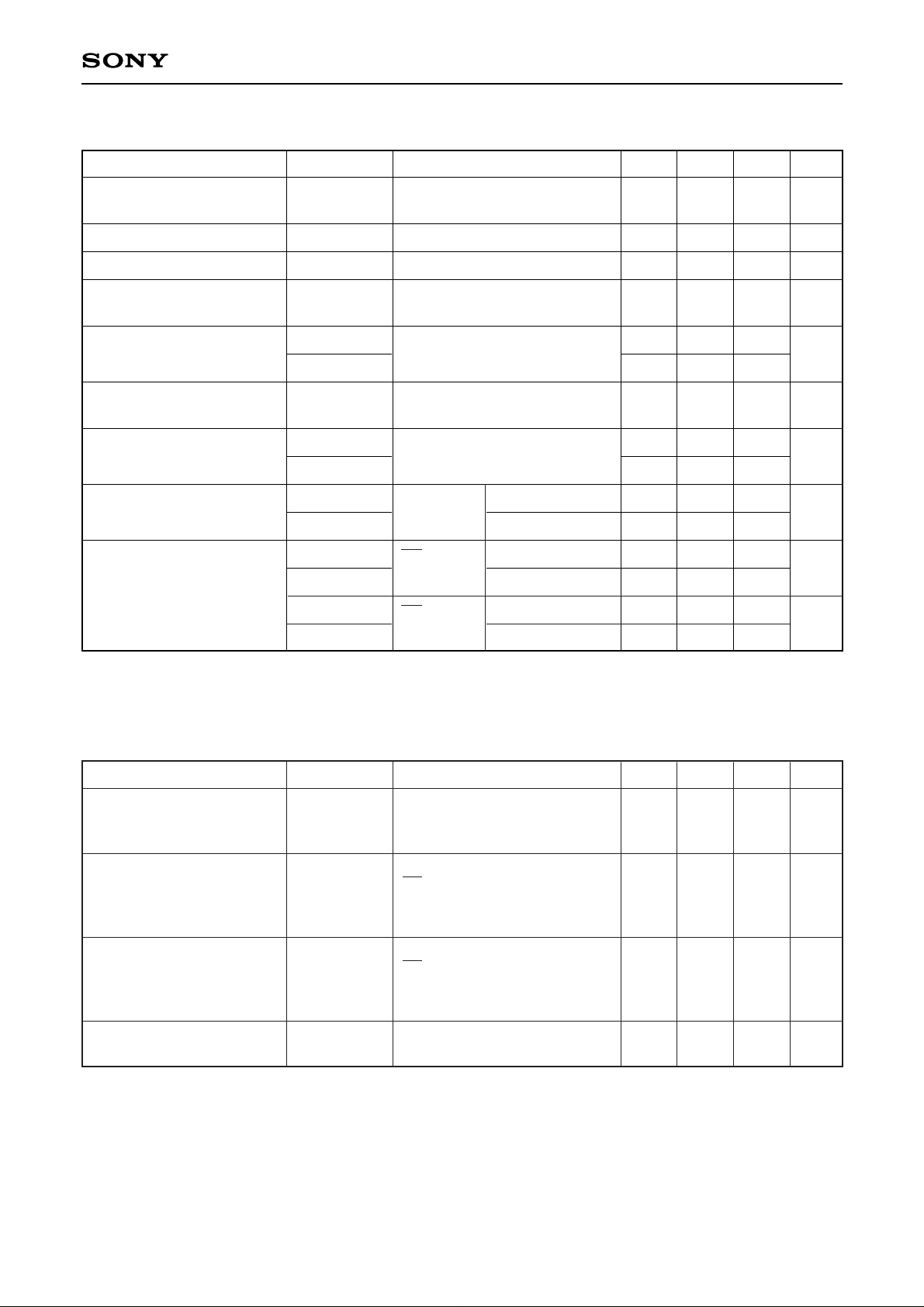
DC characteristics (Fc = 35MSPS, VDD = 5 V, VRB = 0.5 V, VRT = 2.5 V, Ta = 25 °C)
Supply current
Reference pin current
Analog input capacitance
Reference resistance
(VRT to VRB)
Self-bias I
Self-bias II
Digital input voltage
Digital input current
Digital output current
IDD
IREF
CIN
RREF
VRB1
VRT1 – VRB1
VRT2
VIH
VIL
IIH
IIL
IOH
IOL
IOZH
IOZL
4.5
230
0.52
1.96
2.13
3.5
–1.1
3.7
Fc = 35MSPS
NTSC ramp wave input
VIN = 1.5 V + 0.07 Vrms
Shorts VRB and VRBS
Shorts VRT and VRTS
VRB = AGND
Shorts VRT and VRTS
VDD = 4.75 to 5.25 V
Ta = –40 to +85 °C
VDD = max
OE = VSS
VDD = min
OE = VDD
VDD = max
16
6.1
8
330
0.56
2.10
2.33
–2.5
6.5
22
8.7
440
0.60
2.24
2.53
0.5
5
5
16
16
mA
mA
pF
Ω
V
V
V
µA
mA
µA
Item Symbol Conditions Min. Typ. Max. Unit
Timing (Fc = 35MSPS, VDD = 5 V, VRB = 0.5 V, VRT = 2.5 V, Ta = 25 °C)
Output data delay
Tri-state output
enable time
Tri-state output
disable time
Clamp pulse width
∗1
TDL
tPZH
tPZL
tPHZ
tPLZ
tcpw
7
5
4
1.75
With TTL 1 gate and 10 pF load
VDD = 4.75 to 5.25 V
Ta = –40 to +85 °C
RL = 1 kΩ, CL = 15 pF
OE = 5 V → 0 V
VDD = 4.75 to 5.25 V
Ta = –40 to +85 °C
RL = 1 kΩ, CL = 15 pF
OE = 0V → 5 V
VDD = 4.75 to 5.25 V
Ta = –40 to +85 °C
Fc = 14MSPS, CIN = 10 µF
for NTSC wave
13
8
6.5
2.75
18
14
11
3.75
ns
ns
ns
µs
Item Symbol Conditions Min. Typ. Max. Unit
VIH = VDD
VIL = 0 V
VOH = VDD – 0.5 V
VOL = 0.4 V
VOH = VDD
VOL = 0 V
∗1
The clamp pulse width is for NTSC as an example. Adjust the rate to the clamp pulse cycle (1/15.75 kHz
for NTSC) for other processing systems to equal the values for NTSC.
Page 9
—9—
CXD1179Q
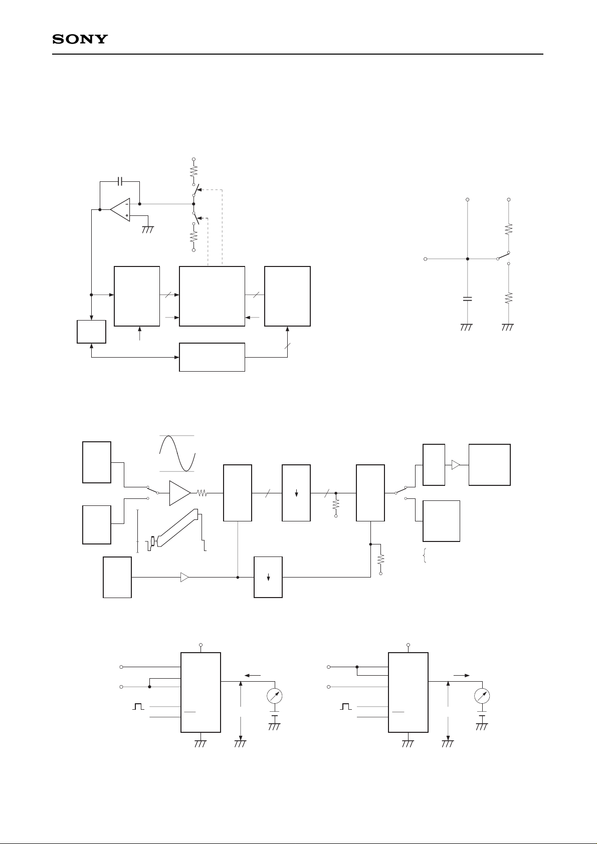
Electrical Characteristics Measurement Circuit
Integral non-linearity error
Differential non-linearity error }measurement circuit
Offset voltage
+V
–V
A < B A > B
COMPARATOR
A8
to
A1
A0
B8
to
B1
B0
DUT
CXD1179Q
BUFFER
S1
S2
88
CONTROLLER
DVM
8
CLK (35MHz)
VIN
“0” “1”
S1: ON
IF A < B
S2: ON IF B > A
000 · · · 00
to
111 · · · 10
Maximum operational speed
Differential gain error }measurement circuit
Differential phase error
S.G.
NTSC
SIGNAL
SOURCE
S.G.
(CW)
CXD
1179Q
10bit
D/A
VECTOR
SCOPE
COUNTER
H.P.F
TTL
ECL
AMP
TTL
ECL
FC
1
2
V
IN 8 8
620
–5.2V
CLK
620
–5.2V
1
2
CX20202A-1
ERROR RATE
D.G
D.P.
40 IRE
MODULATION
100
0
–40
SYNC
0.5V
2.5V
IAE
BURST
2.5V
0.5V
Fc – 1kHz
Digital output current measurement circuit
VDD
VRT
VIN
VRB
CLK
OE
GND
2.5V
0.5V
VOH
+
–
I
OH
VDD
VRT
VIN
VRB
CLK
OE
GND
VOL
+
–
I
OL
2.5V
0.5V
CL
DVDD
RL
RL
Measurement
point
To output pin
Tri-state output measurement circuit
Note) CL includes capacitance of the probe and others.
Page 10
—10—
CXD1179Q
S (1) C (1) S (2) C (2) S (3) C (3) S (4) C (4)
MD (0) MD (1) MD (2) MD (3)
RV (0) RV (1) RV (2) RV (3)
S (1) C (1) S (3) C (3)H (3)H (1)
LD (–1) LD (1)
C (0) S (2) C (2) S (4)H (0) H (2) H (4)
LD (–2) LD (0) LD (2)
Out (–2) Out (–1) Out (0) Out (1)
Vi (1) Vi (2) Vi (3) Vi (4)
Analog input
External clock
Upper comparators block
Upper data
Lower reference voltage
Lower comparators A block
Lower data A
Lower comparators B block
Lower data B
Digital output
Timing Chart 3
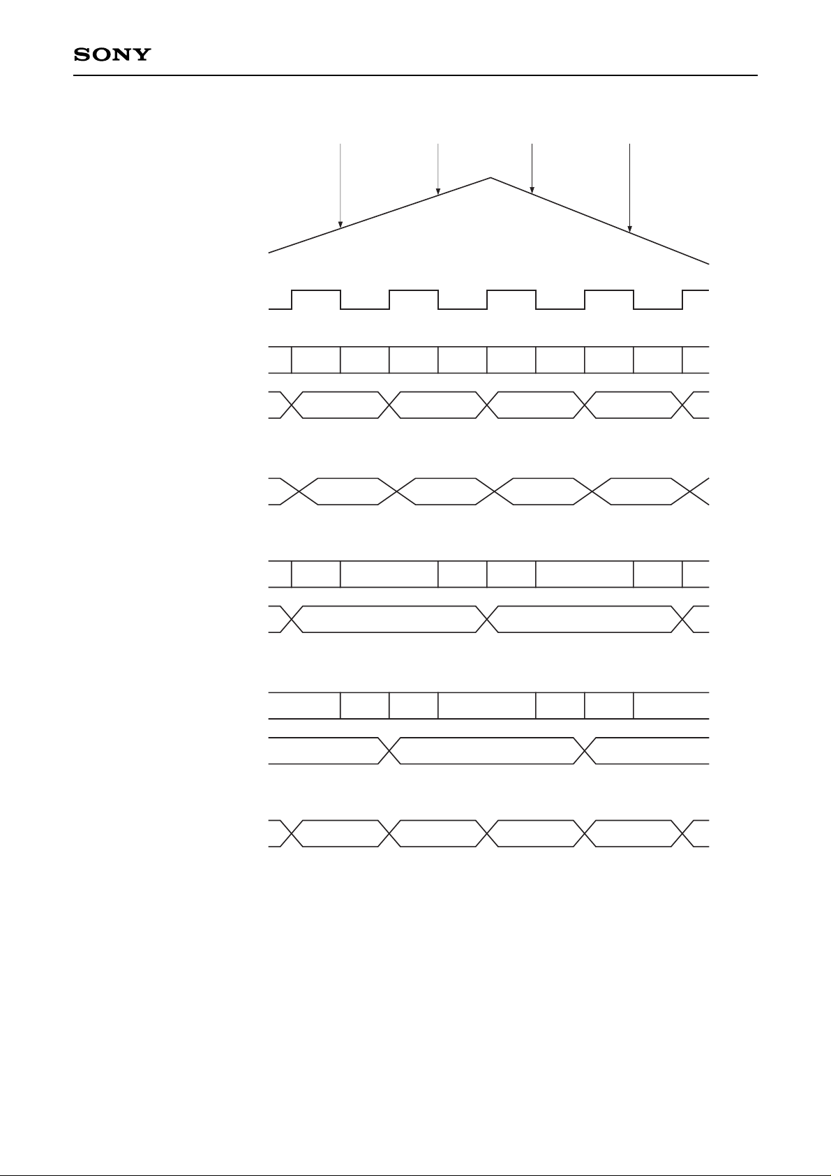
Operation (See Block Diagram and Timing Chart 3)
1. The CXD1179Q is a 2-step parallel system A/D converter featuring a 4-bit upper comparators group and 2
lower comparators groups of 4-bit each. The reference voltage that is equal to the voltage between VRT –
VRB/16 is constantly applied to the upper 4-bit comparator block. Voltage that corresponded to the upper
data is fed through the reference supply to the lower data. VRTS and VRBS pins serve for the self
generation of VRT (Reference voltage top) and VRB (Reference voltage bottom).
Page 11

—11—
CXD1179Q
2. This IC uses an offset cancel type comparator and the comparator operates synchronously with an
external clock. These modes are respectively indicated on the timing chart with S, H, C symbols. That is,
the comparator performs input sampling (auto zero) mode, input hold mode and comparison mode using
the external clock.
3. The operation of respective parts is as indicated in the chart. For instance input voltage Vi (1) is sampled
with the falling edge of the first clock by means of the upper comparator block and the lower comparator A
block.
The upper comparators block finalizes comparison data MD (1) with the rising edge of the first clock.
Simultaneously the reference supply generates the lower reference voltage RV (1) that corresponded to
the upper results. The lower comparator block finalizes comparison data LD (1) with the rising edge of the
second clock. MD (1) and LD (1) are combined and output as Out (1) with the rising edge of the 3rd clock.
Accordingly there is a 2.5 clock delay from the analog input sampling point to the digital data output.
Operation Notes
1. Power supply and ground
To reduce noise effects, separate the analog and digital systems close to the device. For both the digital
and analog power supply pins, use a ceramic capacitor of about 0.1 µF set as close as possible to the pin
to bypass to the respective grounds.
2. Analog input
Compared with the flash type A/D converter, the input capacitance of the analog input is rather small.
However it is necessary to conduct the drive with an amplifier featuring sufficient band and drive capability.
When driving with an amplifier of low output impedance, parasite oscillation may occur. That may be
prevented by inserting a resistance of about 100 Ω in series between the amplifier output and A/D input.
3. Clock input
The clock line wiring should be as short as possible also, to avoid any interference with other signals,
separate it from other circuits.
4. Reference input
Voltage between VRT to VRB is compatible with the dynamic range of the analog input. Bypassing VRT and
VRB pins to analog ground, by means of a capacitor about 0.1 µF, the stable characteristics of the
reference voltage are obtained. By shorting VRT and VRTS, VRB and VRBS, the self-bias function that
generates VRT = about 2.6 V and VRB = about 0.6 V, is activated.
5. Timing
Analog input is sampled with the falling edge of CLK and output as digital data with a delay of 2.5 clocks
and with the following rising edge. The delay from the clock rising edge to the data output is about 13ns.
6. OE pin
By connecting OE to DVSS output mode is obtained. By connecting OE to DVDD high impedance is
obtained.
Page 12
—12—
CXD1179Q
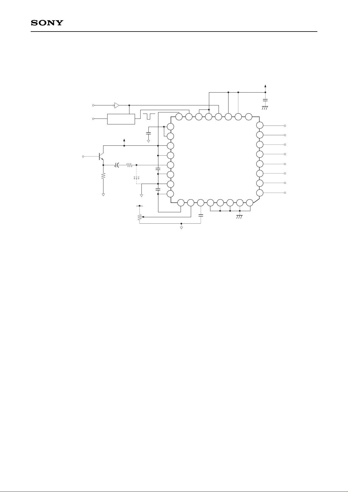
Application Circuit
(1) When clamp is used (self bias used)
2
3
4
5
6
7
8
9
10
11
12
13
14
15
16
17
18
19
20
21
22
23
24
25
26 27
28
32
1
0.1µ
OPEN
LATCH
CK
Q
∗
0.01µ
CLAMP PULSE IN
CLOCK IN
ACO4
+5V (Analog)
VIDEO IN
75Ω
10µ
0.1µ
10P
+5V (Analog)
0.01µ
VREF
20k
GND (Analog)
29
30
31
0.01µ
GND (Digital)
+5V (Digital)
D7
D6
D5
D4
D3
D2
D1
D0
∗
The clamp pulse is latched by the sampling clock of ADC, but that is not necessary for basic clamp operation.
However, slight small beat may be generated as vertical sag according to the relationship between the
sampling frequency and the clamp pulse frequency. At such time, the latch circuit is effective in this case.
Page 13
—13—
CXD1179Q
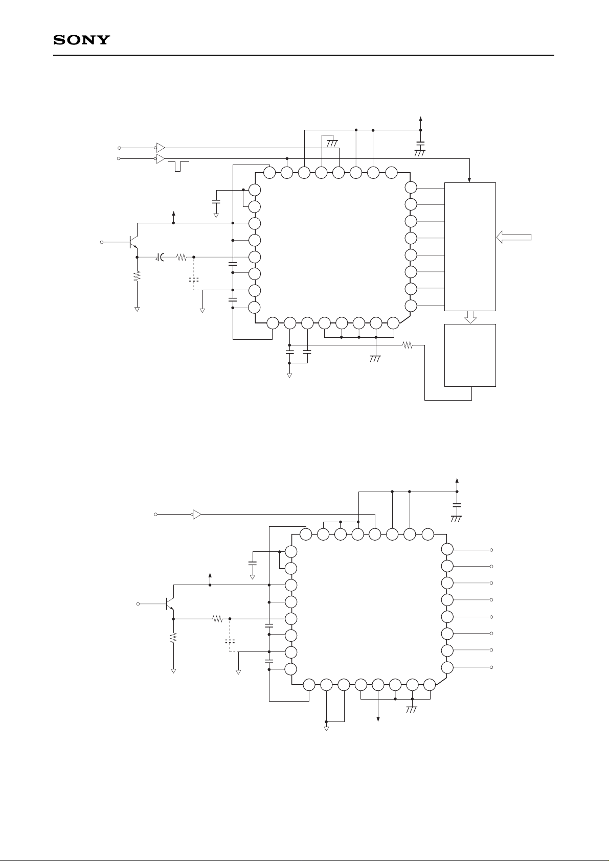
(2) Digital clamp (self bias used)
2
3
4
5
6
7
8
9
10
11
12
13
16
17
18
19
20
21
22
23
24
25
26
27
28
32
1
0.1µ
OPEN
0.01µ
CLOCK IN
ACO4
+5V (Analog)
VIDEO IN
75Ω
10µ
0.1µ
10P
0.01µ
GND (Analog)
29
30
31
GND (Digital)
DAC,
PWM,
etc.
Latch,
Subtracter,
Comparator,
etc.
1415
CLAMP
PULSE IN
+5V (Digital)
Clamp Level
setting data
(3) When clamp is not used (self bias used)
2
3
4
5
6
7
8
9
10
11
12
13
1415
16
17
18
19
20
21
22
23
24
25
26 27
28
32
1
OPEN
0.01µ
CLOCK IN
ACO4
+5V (Analog)
VIDEO IN
75Ω
0.1µ
10P
0.01µ
GND (Analog)
29
30
31
GND (Digital)
+5V (Digital)
+5V (Digital)
0.1µ
D7
D6
D5
D4
D3
D2
D1
D0
Page 14
SONY CODE
EIAJ CODE
JEDEC CODE
PACKAGE MATERIAL
LEAD TREATMENT
LEAD MATERIAL
PACKAGE MASS
EPOXY RESIN
SOLDER PLATING
42 ALLOY
32PIN QFP (PLASTIC)
9.0 ± 0.2
7.0 – 0.1
1.5 – 0.15
(8.0)
0.1 – 0.1
+ 0.2
+ 0.35
+ 0.3
0.50
0.127 – 0.05
+ 0.1
0° to 10°
0.8
0.3 – 0.1
+ 0.15
1
8
9
32
16
1724
25
M
0.24
0.2g
QFP-32P-L01
QFP032-P-0707
0.1
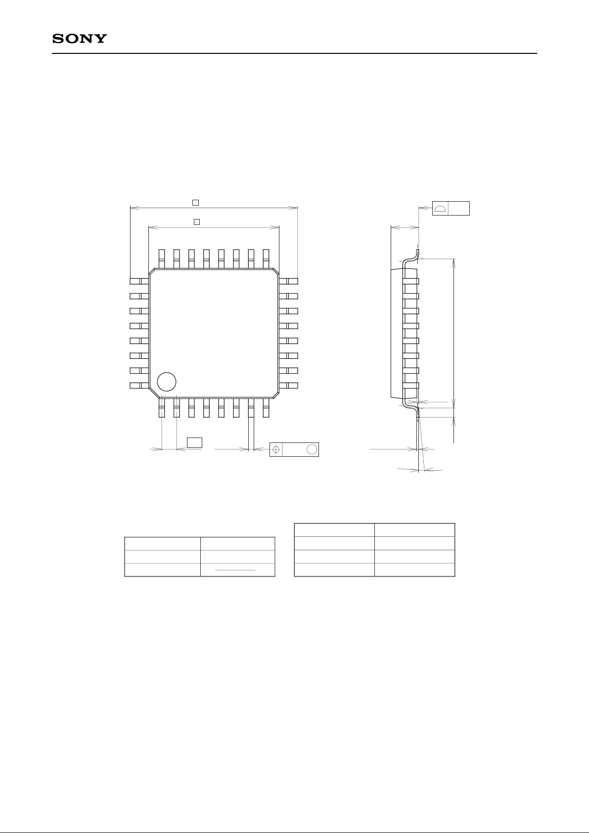
Package Outline Unit : mm
CXD1179Q
—14—
 Loading...