

Page 1
Advance Data Sheet, Rev. 1
CW20P-Type
CW Tunable, Wavelength-Stabilized Laser Module
Applications
■
SONET/SDH extended-reach
■
Long-haul, very dense, wave-division multiplexing
(DWDM)
■
High-speed data communication
■
Flexible wavelength systems
Description
June 2001
Offering multiple channel selections and SONET/SDH compatibility, the CW20P-Type CW DBR Laser Module is manufactured in a 24-pin metallic DIP with a polarization-maintaining
fiber (PMF) pigtail.
Features
■
Tunable up to twenty ITU-T 50 GHz channels
■
For use with lithium niobate modulators
■
Integrated Etalon stabilizer
—Replaces external wavelength lockers
■
1528.77 nm to 1610.0 nm wavelengths
■
Compact design
■
Remote programmability
■
Asynchronous serial interface for module communication
■
High output power, up to 20 mW
■
Low profile, 24-pin package
The CW20P-type laser modules are designed for use
in transmission systems and high-speed data communication applications. The device supports
20 wavelengths. The module uses an RS-232 interface to adjust various module functions such as
wavelength. In addition, the interface provides accessibility to the alarm and monitor outputs.
The modules meet all present
gies
* GR-253-CORE requirements and the ITU-T
Telcordia Technolo-
G.957 and G.958 recommendations. The modules
are also suited for extended distance data and networking applications when used in conjunction with a
lithium niobate modulator.
The CW20P uses a 1.5 µm distributed Bragg reflector (DBR) laser with an integrated wavelength stabilizer. By integrating the wav elength stabilizer with the
DBR laser chip, the device offers a compact, costeffective solution for low-dispersion transmission.
Devices are provided at wavelengths that are compatible with the ITU-T wavelength standards at
200 GHz, 100 GHz, and 50 GHz. The package also
contains a thermoelectric cooler, thermistor, backfacet monitor, and optical isolator. The laser module
requires 5 V, –5.2 V, and 3.3 V.
■
Laser bias monitor alarm
■
Module enable/disable input
*
Telcordia Technologies
Inc.
is a trademark of T el cordia Technologies,
Page 2
CW20P-Type Advance Data Sheet, Rev. 1
CW Tunable, Wavelength-Stabilized Laser Module June 2001
Module Processing
The module can withstand normal wave soldering processes. The complete transmitter module is not hermetically sealed; therefore, it should not be immersed
in or sprayed with any cleaning solution or solvents.
The process cap and fiber pigtail jacket can deform at
temperatures greater than 85 °C. The transmitter pins
can be wave-soldered at a maximum temperature of
250 °C for 10 seconds.
Connector Options
The standard fiber-optic pigtail is an 8 µm core PMF
panda-type fiber. (914 µm) diameter, tight-buffered
outer jacket. The standard length is 39 in. ± 4 in.
(1 m ± 10 cm) and is terminated with an
ST
®
optical
connector.
Installation Considerations
Although the module has been designed with ruggedness in mind, care should be used during handling.
The optical connector should be kept free from dust,
and the process cap should be kept in place as a dust
cover when the device is not connected to a cable. If
contamination is present on the optical connector, the
use of canned air with an extension tube should
remove any debris. Other cleaning procedures are
identified in the
nical Note (TN95-010LWP).
Cleaning Fiber-Optic Assemb lies
Tech -
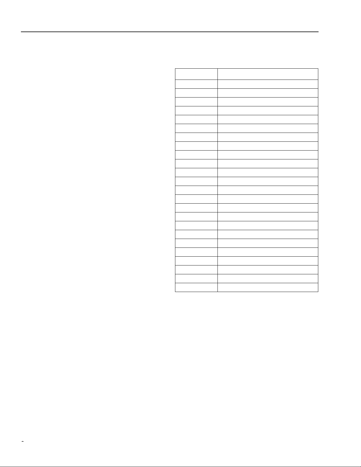
Pin Information
Table 1. Pin Descriptions
Pin Number Name
1 Ground (TEC)
2 Back-facet Monitor
3 Bias Monitor/Laser Degrade Alarm1
4 CW Enable
5 NUC
2
6 Ground
7 Wavelength-Deviation Error Alarm
8 RS-232 Interface (Tx)
9 RS-232 Interface (Rx)
10 Dither Input
11 Ground
12 V
13 V
14 V
(TEC supply voltage)
TEC
EE
CC
15 Ground
16 NUC
2
17 Ground
18 NUC
2
19 Ground
20 NUC
2
21 Ground
22 NUC
2
23 Ground
24 V
1. Laser back-facet and bias alarm functions are customer-use
options that are not required for normal operations of the transmitter
and are normally used during manufacture and for diagnostics.
The output will optionally be either a logic signal or an analog voltage. All alarm, select, and enable signals are active-high.
2. NUC = no user connection.
CC
1
22
Agere Systems Inc.
Page 3

Advance Data Sheet, Rev. 1 CW20P-Type
June 2001 CW Tunable, Wavelength-Stabilized Laser Module
Absolute Maximum Ratings
Stresses in excess of the absolute maximum ratings can cause permanent damage to the device. These are absolute stress ratings only. Functional operation of the device is not implied at these or any other conditions in excess
of those given in the operations sections of the data sheet. Exposure to absolute maximum ratings for extended
periods can adversely affect device reliability.
Parameter
Supply Voltage (positiv e) V
Supply Voltage (negati ve) V
Operating Case Temperature Range T
Storage Case Temperature Range T
Symbol Min Max Unit
CC
EE
C
stg
—5.5V
— –6.0 V
070°C
–40 85 °C
Lead Soldering Temperature/Time — — 250/10 °C/s
Relative Humidity (noncondensing) RH — 85 %
Minimum Fiber-Bend Radius — 1.5 (38.1) — in. (mm)
Characteristics
(Minimum and maximum values specified over operating case temperature range at 50% duty cycle data signal.
Typical values are measured at room temperature unless otherwise noted.)
Table 2. Electrical Characteristics
Parameter Symbol Min Typ Max Unit
V
λ
ALARM N
V
λ
V
ALARM
λ
ALARM
V
λ
ALARM N
V
LD
CC
CC
EE
EE
DISS
DIS
EN
V
ALARM
ALARM
TEC
TEC
4.75 5.0 5.25 V
— 350 500 mA
–5.46 –5.2 –4.94 V
——250mA
—10 — W
4.2 — — V
0.0 — 0.8 V
0
4.05
–20
4.05
0
—
—
—
—
—
—
—
I
BOL
0.6
—
20
—
0.6
x 125%
V
V
pm
V
V
mA
—1 2 A
3.2 3.3 3.5 V
dc Power Supply Voltage V
dc Power Supply Current I
dc Negative Supply Voltage V
dc Negative Supply Current I
Power Dissipation P
Module Disable Voltage (TTL) V
Module Enable Voltage (TTL) V
IH
IL
λ Deviation Alarm:
Levels (CMOS) V
Levels (CMOS) V
OL
OH
Setting
Laser Degrade Alarm:
Levels (CMOS) V
Levels (CMOS) V
Setting
OH
OL
TEC Current I
TEC Voltage V
Agere Systems Inc.
3
Page 4

CW20P-Type Advance Data Sheet, Rev. 1
CW Tunable, Wavelength-Stabilized Laser Module June 2001
Characteristics
(continued)
Table 3. Optical Characteristics
Parameter Symbol Min Typ Max Unit
Average Optical-Fiber Power Output (BOL)
1
F
P
13.0 — — dBm
Output Power Variation (BOL) ∆P –0.5 — 0.5 dB
Frequency Drift ∆λ
Center Wavelength Range (See Table 6.) λ
2
Side-mode Suppression Ratio
1. Output power definitions and measurement per ITU-T Recommendation G.957.
2.
Ratio of the average output power in the dominant longitudinal mode to the power in the most significant side mode under fully
modulated conditions.
C
C
SMSR 32 — — dB
–2.5 — 2.5 GHz
1528.77 — 1610.53 nm
Qualification and Reliability
To help ensure high product reliability and customer satisfaction, Agere Systems is committed to an intensive quality program that starts in the design phase and proceeds through the manufacturing process. Optoelectronics modules are qualified to Agere Systems internal standards using MIL-STD-883 test methods and procedures and using
sampling techniques consistent with
the intent of
Telcordia
reliability practices TR-NWT-000468 and TA-TSY-000983. In addition, the Agere Systems
design, development, and manufacturing facility has been certified to be in full compliance with the latest
9001 Quality System Standards.
Telcordia Technologies
requirements. This qualification program fully meets
ISO
*
Laser Safety Information
Class IIIb Laser Product
All versions of the CW20P-type modules are classified as Class IIIb laser products per FDA/CDRH, 21 CFR 1040
Laser Safety requirements. The device will be classified with the FDA under an accession number to be determined.
This product complies with 21 CFR 1040.10 and 1040.11.
8 µm/125 µm diameter single-mode fiber pigtail with 914 µm tight-buffered jacket and connector.
Product is not shipped with power supply.
Caution: Use of controls, adjustments, and procedures other than those specified herein may result in
hazardous laser radiation exposure.
DANGER
INVISIBLE LASER RADI ATION
IS EMITTED FROM THE END
OF FIBER OR CONNECTOR
Avoid direct exposure to beam
Do not view beam directly with
optical instrum e nt s
INVISIBLE LASER RADIATION EMITTED FROM END OF FIBER OR CONNECTOR
Class IIIb Laser Product FDA/CDRH , 21 CFR 1040 Max. Output: 40 mW Wavelength: 1.5 µm
Avoid exposure to beam
*
ISO
is a registered trademark of The International Organization for Standardization.
4
Agere Systems Inc.
Page 5

Advance Data Sheet, Rev. 1 CW20P-Type
June 2001 CW Tunable, Wavelength-Stabilized Laser Module
Outline Drawings
Dimensions are in inches and (millimeters).
2.89
(73.4)
2.008
(51.00)
(TOP VIEW)
0.012
(0.3)
STANDOFF
HEIGHT
1.5
(38.1)
PIN 13
PIN 12
0.018
(0.46)
DIA
1.100
(27.94)
0.100
(2.54)
1.075
(27.31)
(SIDE VIEW)
1.025
(26.04)
PIN 24
3.50
(8.89)
PIN 1
0.085
(2.16)
STANDOFF
(TYP. 4 PLCS)
0.39
(10.00)
MAX
0.28
(7.00)
MAX
0.50
(12.70)
39.37
(1000)
0.236
(5.99)
Agere Systems Inc.
4 x
0.106 (2.69) THRU
∅
0.236
(5.99)
(BOTTOM VIEW)
1-1263 (F)
5
Page 6

CW20P-Type Advance Data Sheet, Rev. 1
CW Tunable, Wavelength-Stabilized Laser Module June 2001
Ordering Information
Table 6. Ordering Information
Product Code ITU Frequency Range
CW22P61 195.15—196.1 1528.77—1536.22 109071530
CW22P51 194.15—195.1 1536.61—1544.13 109071548
CW22P41 193.15—194.1 1544.53—1552.12 109071555
CW22P31 192.15—193.1 1552.52—1560.2 109071563
CW22P21 191.15—192.1 1560.61—1568.36 109071571
CW22P911 190.15—191.1 1568.77—1576.61 109071589
CW22P901 189.15—190.1 1577.03—1584.95 109071597
CW22P891 188.15—189.1 1585.36—1593.37 109071605
CW22P881 187.15—188.1 1593.79—1601.88 109071613
CW22P871 186.15—187.1 1602.31—1610.49 109071621
Related Product Information
Product Code Description
2623N 10 Gbits/s Single-Drive Lithium Niobate Modulator DS00-331LWP
2623CSA 10 Gbits/s Single-Drive Lithium Niobate Modulator
(THz)
with Integrated Attenuator
Wavelength Range
(nm)
Comcode
Document
Number
DS00-331 LWP
For additional information, contact your Agere Systems Account Manager or the following:
INTERNET:
E-MAIL:
N. AMERICA: Agere Systems Inc., 555 Union Boulevard, Room 30L-15P-BA, Allentown, PA 18109-3286
ASIA PACIFIC: Agere System s Sing apore Pte. Ltd., 77 Science Park Drive, #03-18 Cintech III, Singapore 118256
CHINA: Agere Systems (Shanghai) Co., Ltd., 33/F Jin Mao Tower, 88 Century Boulevard Pudong, Shanghai 200121 PRC
JAPAN: Agere Systems Japan Ltd., 7-18, Higashi-Gotanda 2-chome, Shinagawa-ku, Tokyo 141, Japan
EUROPE: Data Requests: DATALINE:
Agere Systems Inc. reserves the right to make changes to the product(s) or information contained herein without notice. No liability is assumed as a result of their use or application. ST is a
registered trademark of Agere Systems Inc.
Copyright © 2001 Lucent Technologies Inc.
All Rights Reserved
June 2001
DS00-370OPTO-1 (Replaces DS00-370OPTO)
http://www.agere.com
docmaster@micro.lucent.com
1-800-372-2447
Tel. (65) 778 8833
Tel. (86) 21 50471212
Tel. (81) 3 5421 1600
Technical Inquiries: OPTOELECTRONICS MARKETING:
, FAX 610-712-4106 (In CANADA:
, FAX (65) 777 7495
, FAX (86) 21 50472266
, FAX (81) 3 5421 1700
Tel. (44) 7000 582 368
1-800-553-2448
, FAX (44) 1189 328 148
, FAX 610-712-4106)
(44) 1344 865 900
(Ascot UK))
 Loading...