

Datasheet CT2578-12-XT-P119, CT2578-12-XT-F84, CT2578-12-QM-P119, CT2578-12-QM-F84, CT2578-12-IN-P119 Datasheet (ACT)
...Page 1
eroflex Circuit Technology – Data Bus Modules For The Future © SCDCT2578 REV B 3/12/98
www.aeroflex.com/act1.htm
TRANSEIVER
TRANSEIVER
CT2578 / CT2581
SIMPLE REMOTE TERMINAL
FOR MIL-STD-1553 / 1760 & McAir
FEATURES
■ Complete RT Protocol
■ Meets MIL-STD-1553 A/B & MIL-STD-1760
■ Simple interface
■ Dual Transceivers (1553 / 1760 or McAir)
■ +5V only Power Supply
■ Low Power (0.15 Watts per Channel)
■ Only validated messages transferred
■ Optional Data Wrap Around
■ Store Released Signal
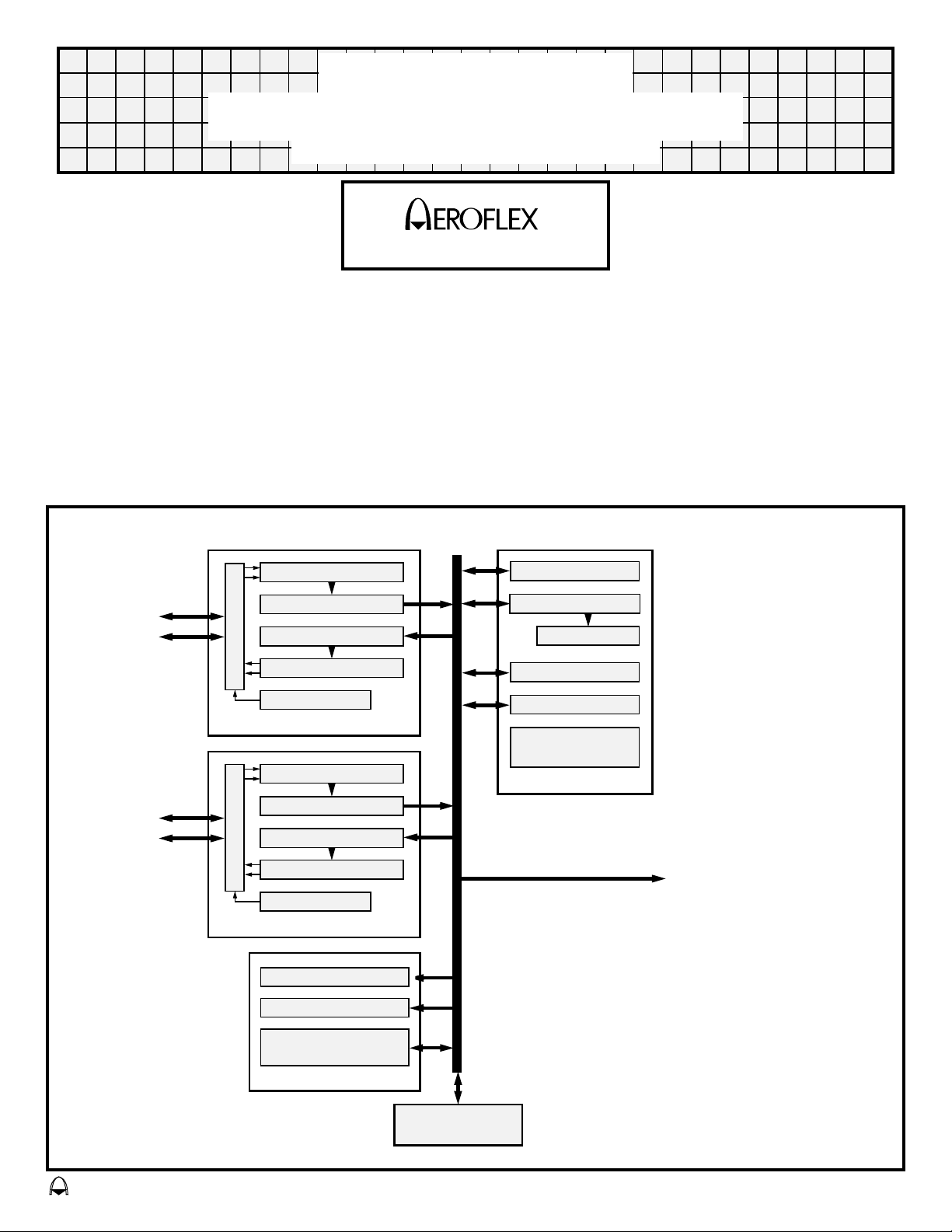
FUNCTIONAL BLOCK DIAGRAM
CIRCUIT TECHNOLOGY
CIRCUIT TECHNOLOGY
www.aeroflex.com/act1.htm
■ Packaging – Hermetic Ceramic
● 119 Lead, 1.28" SQ. x .16" PGA
● 84 Lead, 1.645" SQ. x .14" CQFP
■
Any Message may be Illegalized
■ McAir Reduced Response Time Option (inh MC1F)
■ Optional 1760 checksum
■ 1760 Header word identification
■ Latched RT Address
■ MIL-PRF-38534 Compliant Circuits Available
BUS 0
BUS 1
MANCHESTER DECODER
16 BIT RECEIVE BUFFER
16 BIT TRANSMIT BUFFER
MANCHESTER DECODER
WATCHDOG TIMER
ENCODER / DECODER
MANCHESTER DECODER
16 BIT RECEIVE BUFFER
16 BIT TRANSMIT BUFFER
MANCHESTER DECODER
WATCHDOG TIMER
ENCODER / DECODER
STORE RELEASED
HEADER WORD IDENT
STATUS REGISTER
STATUS REGISTER
COMMAND REGISTER
WORD COUNTER
LAST COMMAND REG
BIT REGISTER
REMOTE TERMINAL
STATE SEQUENCER
RT PROTOCOL
CMD / HRD / DATA
1760 CHECKSUM
GENERATION/VALIDATION
1760 OPTIONS
32 WORD
DATA MEMORY
Page 2

GENERAL DESCRIPTION SIGNAL DESCRIPTIONS
CT2578 is for use in simple Remote Terminal applications
without the need for a processor or software development.
It provides the complete protocol for a Remote Terminal, Signal is connected to the positive side of the external data bus
supporting all types of message transfers including all 15 mode
codes, with comprehensive error checking. Error handling of
data is not required by the subsystem. The user interface is a 16
bit bidirectional highway with a few control lines.
The low power transceivers are capable of providing the output
voltage required by MIL-STD-1760 and are powered by a +5V
supply.
If sinusoidal (McAir) transceivers are required then the part
number becomes CT2581. This is the only difference between
CT2578 and CT2581.
A 32 word data buffer memory is used to store messages until
validation is complete. Only validated messages are transferred
to the subsystem at a rate of 500 nS per word. Data to be
transmitted is transferred from the subsystem to this buffer
memory at a maximum rate of 1 uS per word. This data memory
may be bypassed in the receive mode and data transferred to the
subsystem on a word by word basis as it is being received.
The device has an optional RT wrap around capability. When
WRAPEN is active, data received at subaddress 1E (30) remains
stored in the data buffer memory (i.e. not transferred to the
subsystem). If followed by a transmit from subaddress 1E the
same data will be transmitted.
There is an option within the device to reduce the response time
in order to conform to other standards such as 1553A and
McAir. In this mode subaddress 1F is allocated a normal
subaddress with subaddress 00 reserved for mode commands.
Any message may be illegalized by applying an active low on the
NME discrete status input. The Remote Terminal will respond
with the Message Error bit set in the status and not use the
information received.
A hardware implementation of the 1760 checksum algorithm
within the device may be enabled via signal NENCHK. When
transmitting, the checksum word is inserted in the last word
position, and when receiving, a valid checksum word will
generate the open drain output (STATUS). The STATUS
output may be hard wired to any of the discrete status inputs (e.g.
Service Request), if it is also hard wired to the input NILLCMD
the device will respond to a failed checksum with the selected
status bit set and not use the data (i.e. not transfer the data to the
subsystem).
In addition to the signal NVCR (valid command word received)
which may be used to illegalize commands, a signal NHDR
(header word received) is available to the subsystem for
1553 / 1760 DATA BUS
DATABUS 0
transformers for bus 0.
NDATABUS 0
Signal is connected to the negative side of the external data bus
transformers for bus 0.
DATABUS 1
Signal is connected to the positive side of the external data bus
transformers for bus 1.
NDATABUS 1
Signal is connected to the negative side of the external data bus
transformers for bus 1.
HARD WIRED
ADDR A-E (Inputs with pull up resistor)
Remote Terminal address inputs for the unit. ADDR A is the
least significant bit and ADDR E is the most significant bit.
These inputs are internally latched every time the unit is reset.
The latched address information is then compared to the
incoming command word.
ADDR P (Input with pull up resistor)
Parity bit for the Remote Terminal address inputs. ADDR P
must be set to ODD parity. This input is latched as above.
WRAPEN (Input with pull down resistor)
Select Remote Terminal wrap around to subaddress 1E. The
Bus Controller sends data to subaddress 1E which remains in the
data buffer memory and is available to be sent back on the very
next command by the Bus Controller. The data in the data buffer
memory in this mode does not get transferred to the subsystem.
If the very next command is not a transmit command to
subaddress 1E, the data buffer memory is flushed and will
respond normally to the next set of commands. If the wrap
around test is enabled, data to subaddress 1E must be transferred
in the correct sequence.
“0" = Normal mode
“1" = Wrap Around mode
MCAIR (Input with pull down resistor)
This signal sets the unit to respond with a status word within
4 uS (dead bus time). Subaddress 1F is also enabled to be a valid
subaddress for data. Normally subaddress 00 and 1F are
reserved for mode codes.
“1" = 4 uS dead bus response time, subaddress 1F used for data.
“0" = 12 uS response time, subaddress 1F used for mode codes.
C16MHZ (Input with pull up resistor)
Free running 16 MHZ clock input.
verification of the 1760 message header.
The RT address lines are latched on RESET as required by
1760. If all six RT address lines go open circuit the store
released signal (STREL) will go high.
The device is packaged in a 119 pin grid array or 84 lead CQFP
package.
SUBSYSTEM INTERFACE
T0-T15 (Bibirectional IO)
16 bit bidirectional highway to transfer all information to / from
subsystem. The user can also utilise this bus to monitor
Command word and Header word (1760 requirement) for
message illegalization.
SCDCT2578 REV B 3/11/98
2
Page 3

NRES (Bibirectional IO with pull up resistor) DISCRETE RT STATUS INPUTS
Bidirectional reset pin. Interface to this pin should be in the form
of an open collector pull down driver. The unit will be reset
when a low level input is asserted on power up. The pin is
bidirectional in that the unit will drive the signal out low after the
status response of the mode code Reset Remote Terminal. Upon
reset the unit will be able to respond immediately after the rising
edge of NRES.
NILLCMD (Input with pull up resistor)
Input to illegalize a command to the Remote Terminal with a
clear status response. The signal is sampled after NVCR except
non mode code receive commands in which case it is sampled
after the last data word has been received. A low on this input
will illegalize the message, no transfers to / from the subsystem
will take place. The device will respond with a clear status
unless a bit has been specifically set. No data will be transmitted
following status.
NVCR (Output)
Early indication that the Remote Terminal has received a
command and the command word is available on T0-T15. This
can be used for message illegalization.
NDATA (Output)
Access to valid data word in real time. Data word available on
T0-T15 during active low signal.
NCMDSTRB (Output)
This signal indicates that a completely validated message has
been received for standard subaddress data activity. Mode
commands with or without data will not generate this signal.
The NCMDSTRB signal is 8.5 uS long and is an indication that
a DMA burst will initiate at the end of NCMDSTRB to transfer
words between the 32 word data memory and the subsystem.
The Command word is available on T0-T15 during this period.
NDATAST (Output)
Signal to transfer normal validated received data from the data
buffer memory to the subsystem at a rate of 500 nS per word via
the T0-T15 highway.
NSSTRB (Input with pull up resistor)
Signal to transfer normal data for transmission from the
subsystem to the data buffer memory at a maximum rate of 1 uS
per word via the T0-T15 highway.
C1MHZ (Output)
Free running 1 MHZ clock to subsystem. NSSTRB must be
synchronised to this clock.
NENVW (Output)
Signal to transfer Vector word from subsystem to unit in
response to ‘Transmit Vector Word’ mode command via the
T0-T15 highway.
NSYNC (Output)
Signal to subsystem indicating receipt of a synchronise mode
commands If the mode code has an associated data word, it will
be available on T0-T15 at this time. If there is no associated data
The following signals are inputs to set the appropriate bits in the
Remote Terminals status word. All inputs are sampled after
NVCR except non mode code receive commands in which case
they are sampled after the last data word has been received. All
status inputs are active low.
NME (Input with pull up resistor)
Message Error, illegalizes message. No transfers to / from the
subsystem will take place. No data will be transmitted following
the status.
NBUSY (Input with pull up resistor)
Subsystem Busy. No data will be transferred to / from the
subsystem and no data will be transmitted following status for
non mode code transfers.
NTF (Input with pull up resistor)
Terminal Flag.
NSR (Input with pull up resistor)
Service Request.
NSSFLAG (Input with pull up resistor)
Subsystem Flag.
1760 SIGNALS
NENCHK (Input with pull up resistor)
Enables / disables the internal hardware checksum generation
and validation. When enabled, the circuitry will check all
incoming data for correct checksum and generate the correct
checksum word for an outgoing data transfer.
“0" = Enable checksum circuitry.
“1" = Disable checksum circuitry.
STATUS (Open drain output)
Open drain output will toggle high or low on each incoming data
word from the 1553 data bus provided NENCHK is enabled.
When the last data word is received the STATUS line is sampled
by the protocol circuitry to determine if the checksum for the
message is valid. At the end of the message, if STATUS is low
then the checksum is not valid. This STATUS signal can be
wired to several different pins to customise the units response to
a checksum failure. STATUS can be wired to signals such as
NILLCMD and NSR which would cause the message to be
illegalized and set Service Request bit in the Status.
NHDR (Output)
In Mil-Std-1760, the first data word of a message is defined as
a Header word. The NHDR signal indicates the presence of the
Header word on the T0-T15 highway as it is received. The
Header is also stored in the data buffer memory along with the
complete message.
STREL (Output)
When the store is released from the aircraft all the Remote
Terminal address inputs go high causing signal STREL to go
high.
word, T0-T15 will be zero.
SCDCT2578 REV B 3/11/98
3
Page 4
1 2 3 4
MESSAGE FORMATS
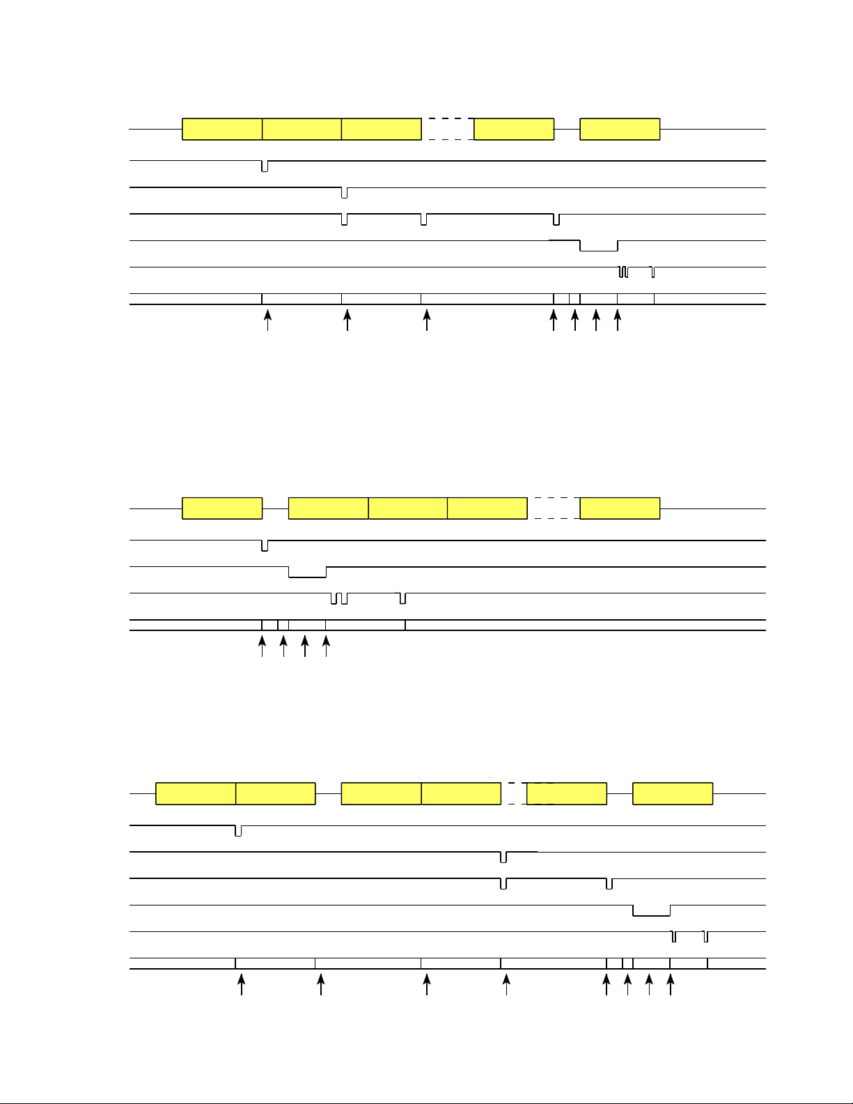
BC TO RT TRANSFER
DATA BUS
DATACOMMAND DATA DATA STATUS
NVCR
NHDR
NDATA
NCMDSTRB
NDATAST
T0-T15
1 2 3 4 5 6 7
1. Valid command word received, contents available on T0-T15 for illegalization purposes.
2. First valid data word (1760 header word) received, contents available on T0-T15 and stored in 32 word data memory.
3. Second valid data word received, contents available on T0-T15 and stored in 32 word data memory.
4. Last valid data word received, contents available on T0-T15 and stored in 32 word data memory. Status bits must be valid within 250nS.
5. Status register contents transferred to transmit buffer.
6. NCMDSTRB indicates valid message received, command word available on T0-T15.
7. Data words transferred from 32 word data memory to subsystem at 500 nS per word.
RT TO BC TRANSFER
DATA BUS
DATA DATA DATACOMMAND STATUS
NVCR
NCMDSTRB
NSSTRB
T0-T15
1. Valid command word received, contents available on T0-T15 for illegalization purposes. Status must be valid within 600 nS.
2. Status register contents transferred to transmit buffer.
3. NCMDSTRB indicates valid message received, command word available on T0-T15.
4. Data words transferred from subsystem to 32 word data memory at 1 uS per word.
RT TO RT TRANSFER (RECEIVING TERMINAL)
DATA BUS
TRAN CMDREC CMD
DATA DATASTATUS
STATUS
NVCR
NHDR
NDATA
NCMDSTRB
NDATAST
T0-T15
SCDCT2578 REV B 3/11/98
1 2 3 85 6 74
4
Page 5
1
3
2
1. Valid receive command word received, contents available on T0-T15 for illegalization purposes.
2. Valid transmit command word received, contents available on T0-T15.
3. Status response of transmitting terminal received.
4. First valid data word (1760 header word) received, contents available on T0-T15 and stored in 32 word data memory.
5. Last valid data word received, contents available on T0-T15 and stored in 32 word data memory. Status bits must be valid within 250nS.
6. Status register contents transferred to transmit buffer.
7. NCMDSTRB indicates valid message received, command word available on T0-T15.
8. Data words transferred from 32 word data memory to subsystem at 500 nS per word.
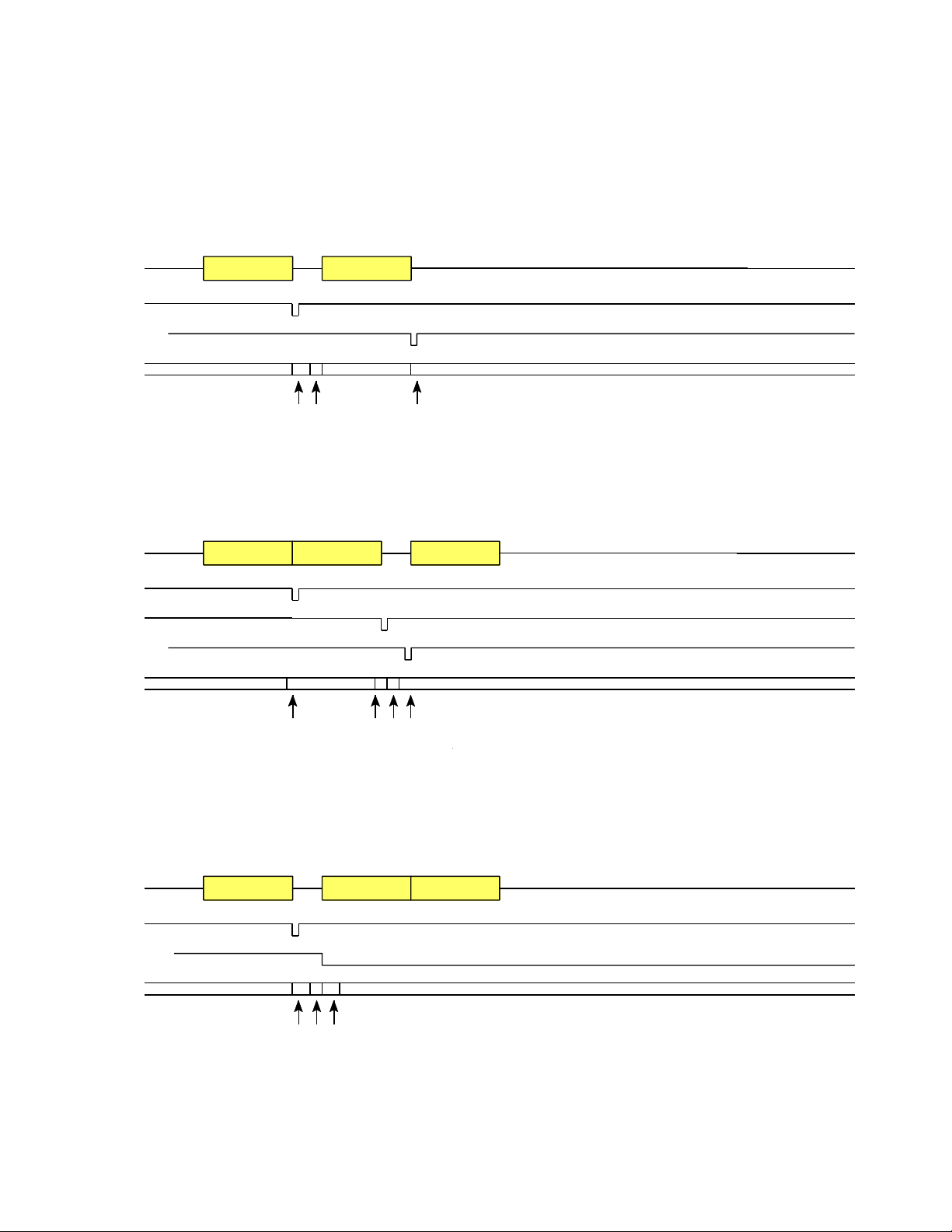
MODE CODES WITHOUT DATA
DATA BUS
COMMAND STATUS
NVCR
NRES/NSYNC
When applicable
T0-T15
1. Valid command word received, contents available on T0-T15 for illegalization purposes. Status must be valid within 600 nS.
2. Status register contents transferred to transmit buffer.
3. Synchronise mode command, T0-T15 = 0.
MODE CODES WITH DATA RECEIVE
DATA BUS
COMMAND STATUS
DATA
NVCR
NDATA
NSYNC
When applicable
T0-T15
1
1. Valid command word received, contents available on T0-T15 for illegalization purposes. Status must be valid within 600 nS.
2. Valid data word received, contents available on T0-T15. Synchronise data word stored in 32 word data memory.
3. Status register contents transferred to transmit buffer after message validation.
4. Synchronise data word(when applicable) transferred from 32 word data memory to main memory and available on T0-T15.
MODE CODES WITH DATA TRANSMIT
DATA BUS
COMMAND STATUS
2
43
DATA
NVCR
NENVW
When applicable
T0-T15
3
1 2
1. Valid command word received, contents available on T0-T15 for illegalization purposes. Status must be valid within 600 nS.
2. Status register contents transferred to transmit buffer after message validation.
3. Vector word (when applicable) transferred from subsystem to transmit buffer.
SCDCT2578 REV B 3/11/98
5
Page 6
1 2 3 4 5 6
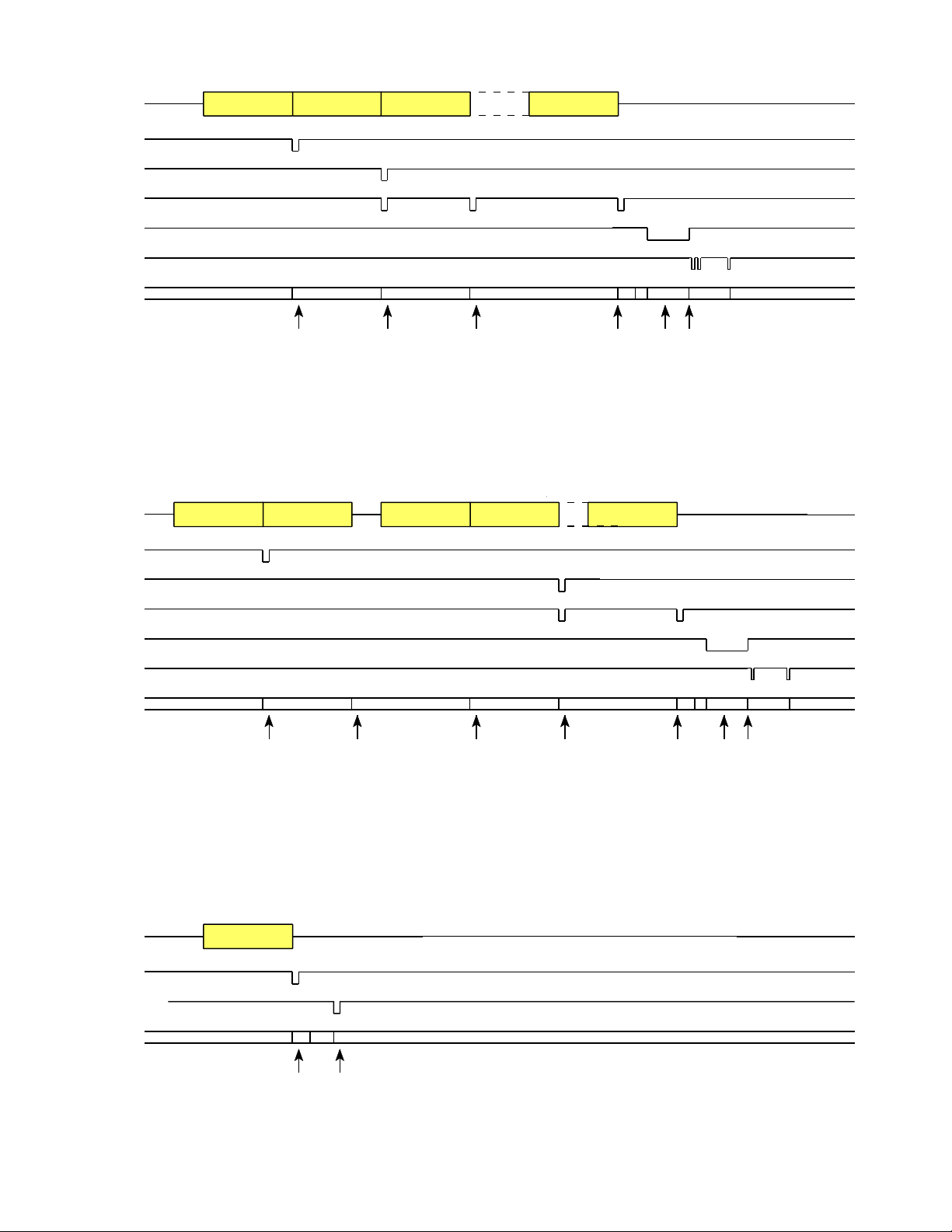
BC TO RT TRANSFER BROADCAST
DATA BUS
DATACOMMAND DATA DATA
NVCR
NHDR
NDATA
NCMDSTRB
NDATAST
T0-T15
1. Valid command word received, contents available on T0-T15 for illegalization purposes.
2. First valid data word (1760 header word) received, contents available on T0-T15 and stored in 32 word data memory.
3. Second valid data word received, contents available on T0-T15 and stored in 32 word data memory.
4. Last valid data word received, contents available on T0-T15 and stored in 32 word data memory. Status bits must be valid within 250nS.
5. NCMDSTRB indicates valid message received, command word available on T0-T15.
6. Data words transferred from 32 word data memory to subsystem at 500 nS per word.
RT TO RT TRANSFER BROADCAST (RECEIVING TERMINAL)
DATA BUS
TRAN CMDREC CMD
DATA DATASTATUS
NVCR
NHDR
NDATA
NCMDSTRB
NDATAST
T0-T15
1 2 3 75 64
1. Valid receive command word received, contents available on T0-T15 for illegalization purposes.
2. Valid transmit command word received, contents available on T0-T15.
3. Status response of transmitting terminal received.
4. First valid data word (1760 header word) received, contents available on T0-T15 and stored in 32 word data memory.
5. Last valid data word received, contents available on T0-T15 and stored in 32 word data memory. Status bits must be valid within 250nS.
6. NCMDSTRB indicates valid message received, command word available on T0-T15 and stored in the 32 word command memory.
7. Data words transferred from 32 word data memory to subsystem at 500 nS per word.
MODE CODES WITHOUT DATA BROADCAST
DATA BUS
COMMAND
NVCR
NRES/NSYNC
When applicable
T0-T15
1
2
1. Valid command word received, contents available on T0-T15 for illegalization purposes. Status must be valid within 600 nS.
2. Synchronise mode command, T0-T15 = 0.
SCDCT2578 REV B 3/11/98
6
Page 7
MODE CODES WITH DATA RECEIVE BROADCAST
DATA BUS
COMMAND
DATA
NVCR
NDATA
NSYNC
When applicable
T0-T15
1
1. Valid command word received, contents available on T0-T15 for illegalization purposes. Status must be valid within 600 nS.
2. Valid data word received, contents available on T0-T15. Synchronise data word stored in 32 word data memory.
3. Synchronise data word (when applicable) transferred from 32 word data memory to main memory and available on T0-T15.
2 3
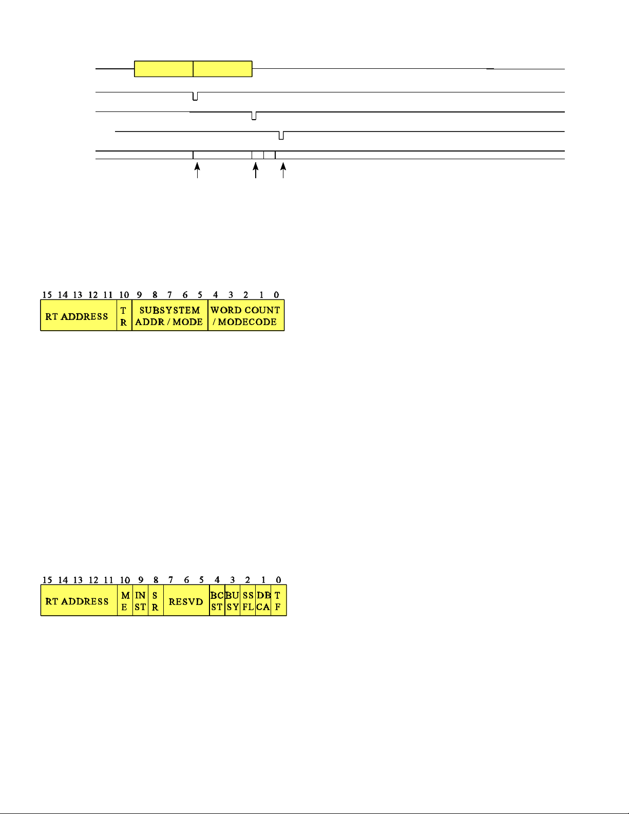
REMOTE TERMINAL DETAIL
RESVD
COMMAND REGISTER
The five most significant bits of the command register contain the
Remote Terminal Address.
Bit 10 of the register is the Transmit / Receive bit. If it is set to '1'
the device will perform the transmit sequence and it is set to '0' it
will perform the receive sequence.
Bits 5 to 9 contain the Subsystem Address but two of these
addresses are reserved and one programable. 11111 (1F) or 00000
(00) indicate that the command is a mode code. The least
significant five bits of the command register are used to decode the
mode code and are not used as the word counter as a mode code
may only have a maximum of one associated word.
111110 (1E) and WRAPEN sets the sequencer up to perform the
wrap around function.
The least significant five bits of the command register contain the
number of data words to be transmitted or received. 11111 is 31
words and 00000 is 32 words.
STATUS REGISTER
ME
Message Error: set internally as a result of an error in the received
message or set externally with a discrete pin to illegalize a
message.
INST
Instrumentation: set to zero.
SR
Service Request: set with a discrete pin.
Reserved: set to zero
BCST
Broadcast Command Received: set internally.
BUSY
Subsystem Busy: set with a discrete pin.
SSFL
Subsystem Flag: set with a discrete pin.
DBCA
Dynamic Bus Control Acceptance: set to zero.
TF
Terminal Flag: set with a discrete pin.
The status register is cleared and the external bits loaded on all
commands except 'Transmit Status' and 'Transmit Last Command'.
The external status bits (both discrete and programable) must be
valid 600 nS from the rising edge of NVCR for transmit commands
and mode codes, and 250 nS from the rising edge of NDATA for
the last data word in a receive message.
If discrete status inputs are not used they may be left open circuit.
STATUS RESPONSE TIME
The response time (all commands) measured from the mid bit zero
crossing of the last bit of the last word to the mid bit zero crossing
of the status word sync is nominally 11.0 uS.
This time period is used to monitor for more data words on the bus.
If a valid sync field followed by four valid Manchester bi-phase bits
are detected then this is considered to be another word on the bus.
The response time may be reduced to 6.0 uS (4.0 uS dead bus
time) by setting the MCAIR input active high.
MESSAGE ILLEGALIZATION
Any command or mode command may be illegalized by setting the
NME input active low. The remote terminal will respond with
status with the Message Error bit set, provided the message was
valid, and not use the information received. There will be no
transfers to or from the subsystem.
SCDCT2578 REV B 3/11/98
7
Page 8

One way to implement this function is to place a latching PROM The device will only consider a command word valid if the
to the T0-T10 data bus. The PROM would only have to decode 11 following conditions are met:bits (5 bits subaddress, 5 bit word count and 1 bit T/R) and have a) It contains the correct sync field.
a one bit output to place a high / low level on the NME input pin. b) Correct Manchester bi-phase (16 bits plus parity).
The upper five bits (T11-T15) are just the Remote Terminal c) Correct parity (odd).
address for the unit which is constant so no decode of these bits is d) Correct terminal address or broadcast address.
necessary. The latching signal for the PROM would be the NVCR e) Does not follow contiguously a valid word on the same bus.
line. The NME signal will remain latched and stable until the next
rising edge of NVCR.
Reserved mode commands are automatically declared illegal by the
device and need not be included in the PROM decode.
All other conditions which require the message error bit to be set c) Correct parity (odd).
The device will only consider a data word valid if the following
conditions are met:-
a) It contains the correct sync field.
b) Correct Manchester bi-phase (16 bits plus parity).
are automatic. d) Follows contiguously a valid word on the same bus.
1760 CHECKSUM
Upon receipt of a valid command word the signal NVCR becomes
active low for 500 nS. (The command word is available on T0-T15
during this period for message illegalization).
The 1760 checksum logic is enabled by setting the input NENCHK
active low.
For transmit messages the checksum word is generated and
On all commands except 'Wrap Around Transmit' the 32 data word
memory is cleared.
inserted in the last word position of the transmitted message.
For received messages the last data word receive (the checksum
RT TO BC TRANSFER
word) is validated. If this word meets the required criteria the
output STATUS remains low. This signal will toggle up and down
for each data word received as it is calculating the checksum.
The open drain output (STATUS) signal may be hard wired to any
of the discrete status inputs to set the required bit of the status
response in the current message. In addition it may be hard wired
to the input NILLCMD which will prevent the message being
written to memory (e.g. if it is required to set the Service Request
bit and not use the data for a failed checksum - hard wire STATUS
to NSR and NILLCMD).
1760 HEADER WORD
In 1760 applications the first data word received is designated the
header word. An output NHDR is provided to indicate the
presence of this word on the highway T0-T15 for verification
purposes. A failed header word may be treated in the same way as
a failed checksum.
STORE RELEASED
The signal STREL is provided in 1760 applications to indicate to
the subsystem that the store is no longer connected to the aircraft.
INITIALISATION OF THE DEVICE
The device must be reset to a known state on power up. (The RT
address will be latched on power up). It will remain inactive until
a valid command word is received. If the device is in the process
of sequencing a command and a new command is received on the
alternative bus, the sequence will be terminated and the device will
If a valid command is received to transmit up to 32 data words the
device will initially respond with Status.
The signal NCMDSTRB goes low for 8.5 uS synchronized to the
1 MHZ clock indicating that a completely validated message has
been received. The transmit Command word appears on T0-T15
at this time.
If the Busy bit of the Status is set the sequence will terminate after
NCMDSTRB.
The end of the NCMDSTRB will initiate the DMA cycle to transfer
the data words from the subsystem to the data buffer memory in a
single burst.
The subsystem enables the first data word onto T0-T15 and applies
a NSSTRB to the device synchronized to the 1 MHZ clock, this
data is stored in the data buffer memory. The subsystem must
continue transferring the correct amount of words to the device in
this manner at a rate of between 62.5 kHz and 1 MHZ.
Data is transferred from the data buffer memory to the output buffer
for transmission as required by the 1553 data bus.
If the 1760 checksum is enabled, the checksum word will be
automatically generated and transmitted as the last data word. For
example, if a Command is received to transmit five data words the
subsystem can load four or five data words. If the subsystem loads
four data words the device will generate the last data word for
transmission. If the subsystem loads five data words the device will
ignore the last data word and transmit the internally generated
checksum word instead.
sequence the new command.
SCDCT2578 REV B 3/11/98
8
Page 9

Error Conditions Action taken by device
1. Invalid command. No response.
Command ignored.
2. Command followed by No status response.
another word. Set message error.
Sequence terminated.
3. Broadcast address. No status response.
Set message error.
Set broadcast.
Sequence terminated.
4. Too few NSSTRB from Message truncated.
subsystem.
5.Too many NSSTRB from Bit 1 of BIT register set.
subsystem. Too many data words will
not be transmitted.
Note: Sequence terminated - termination will take place before
signal NCMDSTRB becomes active, therefore no transfers to /
from subsystem will occur.
BC TO RT TRANSFER
The end of the NCMDSTRB will initiate the DMA cycle to transfer
the data words from the data buffer memory to the subsystem. The
first word received is enabled onto T0-T15 and the signal
NDATAST is pulsed low. This sequence is repeated for each data
word that was received.
Error Conditions Action taken by device
1. Invalid command. No response.
Command ignored.
2. Invalid data word. No status response.
Set message error.
Sequence terminated.
3. Non contiguous data. No status response.
Set message error.
Sequence terminated.
4. Too few data words. No status response.
Set message error.
Sequence terminated.
5. Too many data words. No status response.
Set message error.
Set broadcast.
Sequence terminated.
RX
CMD
If a valid command is received to receive up to 32 data words and
the second word is another command word then an RT to RT
transfer has been set up (see RT to RT transfer).
All valid data words received are stored in the data buffer memory
until message validation is complete after which the device will
respond with Status.
If the command was a broadcast the status transmission will be
suppressed and the broadcast bit in the status register set.
Data words are also available on T0-T15 as they are received
indicated by signal NDATA.
Only after the message has been completely validated will the data
be transferred to the subsystem in a single burst at 500 nS per
word. This ensures that only complete validated messages are
transferred to the subsystem.
When a complete validated message is stored in the data buffer
memory the signal NCMDSTRB goes low for 8.5 uS synchronized
to the 1 MHZ clock indicating that a completely validated message
has been received. The receive Command word appears on T0-T15
at this time.
If the Busy bit of the Status is set the sequence will terminate after
NCMDSTRB.
DATA DATA DATA
*
STATUS
Note: Sequence terminated - termination will take place before
signal NCMDSTRB becomes active, therefore no transfers to /
from subsystem will occur.
RT TO RT TRANSFER
RX
CMD
To initiate an RT to RT transfer the Bus Controller will send a
receive command to RTA followed contiguously by a transmit
command to RTB.
RTB will respond with status and contiguous data (see RT to BC
transfer).
RTA (the receiving terminal) will receive the status and data
transmitted by RTB and store the received data in the data buffer
memory until the entire RT to RT transfer has been validated, after
which it will respond with its own status provided it was not a
broadcast command, in which case the status transmission will be
suppressed and the broadcast bit set. It will then transfer the data
to the subsystem (see BC to RT transfer).
The error detection for the transmitting terminal will be the same
as for RT to BC transfer. The error detection for the receiving
terminal is as follows:-
TX
CMD
STATUS STATUS
*
DATA
*
SCDCT2578 REV B 3/11/98
9
Page 10

Error Conditions Action taken by device Error Conditions Action taken by device
1. Invalid command. No response.
Command ignored.
2. Non contiguous No status response.
command words. Set message error.
Sequence terminated.
3. Transmit command No status response.
followed by another word Set message error.
(excluding command Sequence terminated.
word for RTA, in which
case it will respond to
the latest command).
4. Transmitting terminal No status response.
does not respond with Set message error.
status within 16 uS. Sequence terminated.
5. Incorrect terminal No status response.
transmitting. Set message error.
Sequence terminated.
6. Non contiguous data No status response.
following status from Set message error.
RTB. Sequence terminated equal to receive word Set message error.
7. Invalid data transmitted No status response.
from RTB. Set message error.
Sequence terminated.
8. Too few or too many No status response.
data words. Set message error.
Sequence terminated.
WRAP AROUND
RX
CMD
TX
CMD
The wrap around capability is for test purposes only. It will test for
transfers to and from the Bus Controller without any sub system
intervention.
The wrap around sequence will commence on receipt of a valid
receive command word containing the wrap around subaddress
(1E) providing the WRAPEN input is set high. The data received
is stored in the data buffer memory and the device will respond
with status. The Bus Controller will then send a transmit command
to subaddress 1E and the data contained in the memory will be
transmitted following the status.
For the test to operate correctly the number of data words to be
transmitted must be the same as the number received.
DATA DATA DATA
*
STATUS
DATA DATA DATA
*
STATUS
1. Invalid receive command. No response.
2. Invalid data word. No status response.
3. Non contiguous data. No status response.
4. Too few or too many No status response.
data words. Set message error.
5. Invalid transmit No response.
command. Command ignored.
6. Transmit command No status response.
followed by another Set message error.
word. Sequence terminated
7.Transmit Broadcast No status response.
address. Set message error.
8. Transmit word count not No data transmission.
count. Sequence terminated.
DYNAMIC BUS CONTROL (00)
DBC
CMD
The device will respond with status.
Error Conditions Action taken by device
1. Invalid command. No response.
2. Command followed by No status response.
another word. Set message error.
3. T/R bit of command set No status response.
to zero. Set message error.
4. Broadcast address. No status response.
5. T/R bit of command set No status response.
to zero and broadcast Set message error.
address Set broadcast.
*
STATUS
Command ignored.
Set message error.
Sequence terminated.
Set message error.
Sequence terminated.
Sequence terminated
Set broadcast.
Sequence terminated.
Command ignored.
Sequence terminated.
Sequence terminated
Set message error.
Set broadcast.
Sequence terminated.
Sequence terminated.
SCDCT2578 REV B 3/11/98
10
Page 11

SYNCHRONIZE WITHOUT DATA WORD (01) INITIATE SELF TEST (03)
SYNC
CMD
The device will respond with status. The NSYNC signal will go
active low for 500 nS. Throughout this period the highway T0T15 will be zero and remain at zero until the next command is
received.
If the command was a broadcast the status transmission will be
suppressed and the broadcast bit in the status register set.
Error Conditions Action taken by device
1. Invalid command. No response.
2. Command followed by No status response.
another word. Set message error.
3. T/R bit of command set No status response.
to zero. Set message error.
4. T/R bit of command set No status response.
to zero and broadcast Set message error.
address Set broadcast.
TRANSMIT STATUS (02)
TX ST
CMD
The status register is not cleared or loaded before it is transmitted,
i.e. it contains the resulting status from the previous command.
Error Conditions Action taken by device
1. Invalid command. No response.
2. Command followed by No status response.
another word. Set message error.
3. T/R bit of command set No status response.
to zero. Set message error.
4. Broadcast address. No status response.
5. T/R bit of command set No status response.
to zero and broadcast Set message error.
address Set broadcast.
*
*
STATUS
Command ignored.
Sequence terminated.
Sequence terminated
Sequence terminated.
STATUS
Command ignored.
Sequence terminated.
Sequence terminated
Set message error.
Set broadcast.
Sequence terminated.
Sequence terminated.
I.S.T
CMD
The device will respond with status..
If the command was a broadcast the status transmission will be
suppressed and the broadcast bit in the status register set.
Error Conditions Action taken by device
1. Invalid command. No response.
2. Command followed by No status response.
another word. Set message error.
3. T/R bit of command set No status response.
to zero. Set message error.
4. T/R bit of command set No status response.
to zero and broadcast Set message error.
address Set broadcast.
TRANSMITTER SHUTDOWN (04)
TX DIS
CMD
The device will respond with status and shutdown the transmitter
on the alternate bus, thus inhibiting any further transmission on that
bus.
Once a transmitter has been shutdown it can only be reactivated by
the mode commands 'Override Transmitter Shutdown' or 'Reset
Remote Terminal'.
If the command was a broadcast the status transmission will be
suppressed and the broadcast bit in the status register set.
Error Conditions Action taken by device
1. Invalid command. No response.
2. Command followed by No status response.
another word. Set message error.
3. T/R bit of command set No status response.
to zero. Set message error.
4. T/R bit of command set No status response.
to zero and broadcast Set message error.
address Set broadcast.
*
*
STATUS
Command ignored.
Sequence terminated.
Sequence terminated
Sequence terminated.
STATUS
Command ignored.
Sequence terminated.
Sequence terminated
Sequence terminated.
SCDCT2578 REV B 3/11/98
11
Page 12

OVERRIDE TRANSMITTER SHUTDOWN (05) OVERRIDE INHIBIT TERMINAL FLAG (07)
TX EN
CMD
The device will respond with status and reactivate a shutdown The device will respond with status and then reactivate the
transmitter on the alternate bus. Terminal Flag bit of the status register.
If the command was a broadcast the status transmission will be
suppressed and the broadcast bit in the status register set.
Error Conditions Action taken by device
1. Invalid command. No response.
2. Command followed by No status response.
another word. Set message error.
3. T/R bit of command set No status response.
to zero. Set message error.
4. T/R bit of command set No status response.
to zero and broadcast Set message error.
address Set broadcast.
*
STATUS
Command ignored.
Sequence terminated.
Sequence terminated
Sequence terminated.
EN TF
CMD
If the command was a broadcast the status transmission will be
suppressed and the broadcast bit in the status register set.
Error Conditions Action taken by device
1. Invalid command. No response.
2. Command followed by No status response.
another word. Set message error.
3. T/R bit of command set No status response.
to zero. Set message error.
4. T/R bit of command set No status response.
to zero and broadcast Set message error.
address Set broadcast.
*
STATUS
Command ignored.
Sequence terminated.
Sequence terminated
Sequence terminated.
INHIBIT TERMINAL FLAG (06)
INH TF
CMD
The device will respond with status and then inhibit any further
setting of the Terminal Flag bit of the status.
Once the Terminal Flag bit has been inhibited it can only be
reactivated by the mode commands 'Override Inhibit Terminal
Flag' or 'Reset Remote Terminal'.
If the command was a broadcast the status transmission will be
suppressed and the broadcast bit in the status register set.
Error Conditions Action taken by device
1. Invalid command. No response.
2. Command followed by No status response.
another word. Set message error.
3. T/R bit of command set No status response.
to zero. Set message error.
4. T/R bit of command set No status response.
to zero and broadcast Set message error.
address Set broadcast.
*
STATUS
Command ignored.
Sequence terminated.
Sequence terminated
Sequence terminated.
RESET REMOTE TERMINAL (08)
RESET
CMD
The device will respond with status after which the bidirectional
signal NRES to the subsystem will go active low for 500 nS.
Transmitter Shutdown mode commands and Inhibit Terminal Flag
mode command will be reactivated.
If the command was a broadcast the status transmission will be
suppressed and the broadcast bit in the status register set.
Error Conditions Action taken by device
1. Invalid command. No response.
2. Command followed by No status response.
another word. Set message error.
3. T/R bit of command set No status response.
to zero. Set message error.
4. T/R bit of command set No status response.
to zero and broadcast Set message error.
address Set broadcast.
*
STATUS
Command ignored.
Sequence terminated.
Sequence terminated
Sequence terminated.
SCDCT2578 REV B 3/11/98
12
Page 13

RESERVED MODE CODES (09-0F) SYNCHRONIZE WITH DATA WORD (11)
RESVD
CMD
The status is not cleared or loaded before it is transmitted with the
message error bit set.
If the command was a broadcast the status transmission will be
suppressed and the broadcast bit in the status register set.
Error Conditions Action taken by device
1. Invalid command. No response.
2. Command followed by No status response.
another word. Set message error.
3. T/R bit of command set No status response.
to zero. Set message error.
4. T/R bit of command set No status response.
to zero and broadcast Set message error.
address Set broadcast.
TRANSMIT VECTOR WORD (10)
TX VW
CMD
On receipt of a valid Command to transmit the Vector Word the
device will initially respond with Status.
After the Status response has been initiated the Vector Word will
be enabled onto T0-T15 from the subsystem with signal NENVW
and transferred to the Output Buffer ready for transmission onto the
1553 data bus following the Status.
Error Conditions Action taken by device
*
*
STATUS
STATUS
Command ignored.
Sequence terminated.
Sequence terminated
Sequence terminated.
VW
SYNC
CMD
The Synchronize data word received is stored in the data buffer
memory until message validation is complete after which the
device will respond with Status.
If the command was a broadcast the status transmission will be
suppressed and the broadcast bit in the status register set.
After the Status response has been initiated the Synchronize Word
will be transferred to the subsystem. The NSYNC signal will go
active low for 500 nS during which time T0-T15 will be set to the
data word received.
1. Invalid command. No response.
2. Command not followed No status response.
contiguously by data Set message error.
word Sequence terminated.
3. Command followed by No status response.
too many words. Set message error.
4. T/R bit of command set No status response.
to one. Set message error.
5. T/R bit of command set No status response.
to one and broadcast Set message error.
address Set broadcast.
DATA
Error Conditions Action taken by device
*
STATUS
Command ignored.
Sequence terminated
Sequence terminated.
Sequence terminated.
1. Invalid command. No response.
Command ignored.
2. Command followed by No status response.
another word. Set message error.
Sequence terminated.
3. T/R bit of command set No status response.
to zero. Set message error.
Sequence terminated
4. Broadcast address. No status response.
Set message error.
Set broadcast.
Sequence terminated.
5. T/R bit of command set No status response.
to zero and broadcast Set message error.
address Set broadcast.
Sequence terminated.
SCDCT2578 REV B 3/11/98
TRANSMIT LAST COMMAND (12)
TX LST LST
CMD
The status response contains the resulting status from the previous
command.
The data word transmitted following the status word contains the
previous valid command (provided it was not Transmit Last
Command).
13
*
STATUS
CMD
Page 14

Error Conditions Action taken by device
SELECTED TRANSMITTER SHUTDOWN (14)
1. Invalid command. No response.
Command ignored.
2. Command followed by No status response.
another word. Set message error.
Sequence terminated.
3. T/R bit of command set No status response.
to zero. Set message error.
Sequence terminated
4. Broadcast address. No status response.
Set message error.
Set broadcast.
Sequence terminated.
5. T/R bit of command set No status response.
to zero and broadcast Set message error. Error Conditions Action taken by device
address Set broadcast.
Sequence terminated.
TRANSMIT BIT WORD (13)
TX BIT BIT
CMD
On receipt of a valid Command to transmit the BIT Word the
device will respond with Status followed by the BIT word, after
which the BIT register is cleared.
Bits 2 to 15 are always zero. Bit 1 is set if the subsystem sends too
many NSSTRB’s.
Error Conditions Action taken by device
1. Invalid command. No response.
2. Command followed by No status response.
another word. Set message error.
3. T/R bit of command set No status response.
to zero. Set message error.
4. Broadcast address. No status response.
5. T/R bit of command set No status response.
to zero and broadcast Set message error.
address Set broadcast.
*
STATUS
WORD
Command ignored.
Sequence terminated.
Sequence terminated
Set message error.
Set broadcast.
Sequence terminated.
Sequence terminated.
TX DIS
CMD
This mode command is not normally used in dual redundant
systems.
The device will respond with status and shut down the transmitter
on the bus designated by the two least significant bits of the data
word.
The bus addresses of the device are channel 0 - 00, channel
1 - 01. If the command is received on the same bus as the
designated shut down bus then the device will respond with status
and no shut down will occur.
Once a transmitter has been shut down it can only be reactivated by
an 'Override Shutdown Command' or 'Reset Remote Terminal'.
If the command was a broadcast the status transmission will be
suppressed and the broadcast bit in the status register set.
1. Invalid command. No response.
2. Command not followed No status response.
contiguously by data Set message error.
word Sequence terminated.
3. Command followed by No status response.
too many words. Set message error.
4. T/R bit of command set No status response.
to one. Set message error.
5. T/R bit of command set No status response.
to one and broadcast Set message error.
address Set broadcast.
OVERRIDE SEL TRANSMITTER SHUTDOWN (15)
TX EN
CMD
This mode command is not normally used in dual redundant
systems.
The device will respond with status and reactivate a shutdown
transmitter on the bus designated by the two least significant bits
of the data word.
The bus addresses of the device are channel 0 - 00 channel
1 - 01. If the command is received on the same bus as the
designated override shutdown bus then the device will respond
with status and no reactivation will occur.
If the command was a broadcast the status transmission will be
suppressed and the broadcast bit in the status register set.
DATA
DATA
*
*
STATUS
Command ignored.
Sequence terminated
Sequence terminated.
Sequence terminated.
STATUS
SCDCT2578 REV B 3/11/98
14
Page 15

1
Error Conditions Action taken by device
1. Invalid command. No response.
Command ignored.
2. Command not followed No status response.
contiguously by data Set message error.
word Sequence terminated.
3. Command followed by No status response.
too many words. Set message error.
Sequence terminated
4. T/R bit of command set No status response.
to one. Set message error.
Sequence terminated.
5. T/R bit of command set No status response.
to one and broadcast Set message error.
address Set broadcast.
Sequence terminated.
RESERVED MODE CODES (16-1F)
RESVD
T/R=1
RESVD
T/R=0
The status is not cleared or loaded before it is transmitted with the
message error bit set.
If the command was a broadcast the status transmission will be
suppressed and the broadcast bit in the status register set.
Error Conditions Action taken by device
T/R=1
1. Invalid command. No response.
2. Command followed by No status response.
another word. Set message error.
STATUS
*
DATA
*
STATUS
Command ignored.
Sequence terminated.
DETAILED TIMING
NVCR
2
T0-T15
STATUS
5
NDATA
NHDR
6
T0-T15
STATUS
1. NVCR pulse duration 500 650 nS
2. NVCR to T0-T15 valid 250 nS
3. NVCR to T0-T15 invalid 250 nS
4. NVCR to discrete status inputs (not rec) 600 nS
5. NDATA & NHDR pulse duration 475 525 nS
6. T0-T15 valid to NDATA & NHDR 250 nS
7. NDATA & NHDR to T0-T15 invalid 250 nS
8. Last NDATA to discrete status inputs (rec) 250 nS
1
C1MHZ
NCMDSTRB
3
T0-T15
1. C1MHZ to NCMDSTRB 75 nS
2. NCMDSTRB duration 8475 8525 nS
3. T0-T15 valid to NCMDSTRB 100 nS
4. NCMDSTRB to T0-T15 invalid 100 nS
3
4
7
8
MIN MAX UNIT
1
2
4
MIN MAX UNIT
T/R=0
3. Invalid command. No response.
4. Command not followed No status response.
contiguously by data Set message error.
word. Sequence terminated.
5. Command followed by No status response.
too many data words. Set message error.
SCDCT2578 REV B 3/11/98
Command ignored.
Sequence terminated.
C1MHZ
NCMDSTRB
NSSTRB
T0-T15
15
1
2
3
5 6
Page 16

MIN MAX UNIT
1. Rising edge of NCMDSTRB to falling 0.5 10.0 uS
edge of first NSSTRB
2. NSSTRB to next NSSTRB 1.0 16.0 uS
3. Rising edge of C1MHZ to falling edge 75 nS
of NSSTRB
4. Falling edge of C1MHZ to rising edge 75 nS
of NSSTRB
5. Falling edge of NSSTRB to data enabled 75 nS
onto T0-T15 from subsystem
6. Rising edge of NSSTRB to data disabled 75 nS
onto T0-T15 from subsystem
C1MHZ
1
NCMDSTRB
2
3
NDATAST
4
5
T0-T15
MIN MAX UNIT
1. Rising edge of NCMDSTRB to falling 225 275 nS
edge of first NDATAST
2. NDATAST to next NDATAST 475 525 nS
3. NDATAST pulse duration 225 275 nS
4. Data valid on T0-T15 to NDATAST 100 nS
5. NDATAST to data invalid on T0-T15 100 nS
16 MHZ CLOCK REQUIREMENT
T 40% 60% of cycle
MIN MAX
TRANSFORMERS
The device requires a 1:2.5 turns ratio for direct coupling and
1:1.79 turns ratio for transformer coupling. The centre tap of the
transformers must be tied to ground.
The suggested transformer are:Technitrol 1553-45
Aeroflex 25T1553-45
1
NRES/NSYNC
2 3
T0-T15
5
NENVW
6
T0-T15
MIN MAX UNIT
1. NRES/NSYNC pulse duration 475 525 nS
2. T0-T15 valid to NSYNC 50 nS
3. NSYNC to T0-T15 invalid 250 nS
4. NVCR to NRES/NSYNC non bcast 27.9 28.1 uS
NVCR to NRES/NSYNC bcast 8.9 9.1 uS
5. NENVW to T0-T15 valid 250 nS
6. NENVW to T0-T15 invalid 500 nS
7. NENVW is reset by NVCR
SCDCT2578 REV B 3/11/98
16
DATA
NDATA
DATA
NDATA
P
1:1.79 1:1.4
P’
Transformer coupled
1:2.5
Direct coupled
0.75Zo
0.75Zo
0.75Zo
0.75Zo
A
A’
Zo
Page 17

OPERATING CONDITIONS
ABSOLUTE MAXIMUM RATINGS
MIN NOM MAX UNIT
E. Not Used
VDD Supply voltage +7 Volts
VSS Supply voltage 0 Volts
VIH High level input voltage VDD+0.5 Volts
VIL Low level input voltage VSS-0.5 Volts
Operating free air temperature range -55 to +125 C
Storage temperature range -65 to +150 C
RECOMMENDED OPERATING CONDITIONS
MIN NOM MAX UNIT
VDD Supply voltage 4.75 5.0 5.5 Volts
Free air temperature range -55 +125 C
ELECTRICAL CHARACTERISTICS
DIGITAL SIGNALS
MIN NOM MAX UNIT
A1. INPUT WITH PULL UP
VIH High level input voltage 2.4 oc Volts
VIL Low level input voltage VSS 0.8 Volts
IIH High level input current 10 uA
IIL Low level input current 35 65 120 uA
CIN Input capacitance 10 pf
F. INPUT OUTPUT
VIH High level input voltage 2.4 VDD Volts
VIL Low level input voltage VSS 0.8 Volts
IIH High level input current 10 uA
IIL Low level input current 10 uA
CIN Input capacitance 10 pf
VOH High level output voltage VDD-0.5 VDD Volts
VOL Low level output voltage 0.4 Volts
IOH High level output current 2.0 5.5 10.0 mA
IOL Low level output current 2.0 5.5 10.0 mA
IHZ High impedance IO current 10 uA
G. INPUT OUTPUT WITH PULL UP
VIH High level input voltage oc oc Volts
VIL Low level input voltage VSS 0.8 Volts
IIH High level input current 10 uA
IIL Low level input current 450 800 1500 uA
CIN Input capacitance 10 pf
VOH High level output voltage VDD-0.5 VDD Volts
VOL Low level output voltage 0.4 Volts
IOH High level output current 0.5 1.0 1.8 mA
IOL Low level output current 1.5 5.0 9.0 mA
DATA BUS SIGNALS
A2. INPUT WITH PULL UP
VIH High level input voltage 2.4 oc Volts
VIL Low level input voltage VSS 0.8 Volts
IIH High level input current 10 uA
IIL Low level input current 450 800 1500 uA
CIN Input capacitance 10 pf
B. INPUT WITH PULL DOWN
VIH High level input voltage 2.4 VDD Volts
VIL Low level input voltage oc 0.8 Volts
IIH High level input current 35 65 120 uA
IIL Low level input current 10 uA
CIN Input capacitance 10 pf
C. OUTPUT
VOH High level output voltage VDD-0.5 VDD Volts
VOL Low level output voltage 0.4 Volts
IOH High level output current 2.0 5.5 10.0 mA
IOL Low level output current 2.0 5.5 10.0 mA
D. OPEN DRAIN OUTPUT
VOH High level output voltage oc Volts
VOL Low level output voltage 0.4 Volts
IOH High level output current 10 uA
IOL Low level output current 2.0 5.5 10.0 mA
H. TRANSMITTER
IO Driver peak output current 600 mA
VO Differential output level 7.0 7.5 9.0 V p-p
point A-A’ (RL=35 ohms)
on 1760 BUS
TRF Rise and fall times 100 200 300 nS
(10%-90% of p-p output)
VOE Output offset 2.5 uS after -90 90 mV
mid bit crossing of parity,
point A-A’ (RL=35 ohms)
VO Differential output level 6.0 7.5 9.0 V p-p
point A-A’ (RL=35 ohms)
on 1553 BUS
H. RECEIVER
VIDR Differential input level 14 20 V p-p
point P-P’ (TXFMR-2.12:1)
CMRR Common mode rejection 45 dB
ratio
VTH Input threshold voltage 0.60 0.82 1.20 V p-p
referred to the bus
(100KHz-1MHz)
SCDCT2578 REV B 3/11/98
17
Page 18

PIN ASSIGNMENTS -PGA
(2578/81-02-XX-YY-P119)
PGA SIGNAL IO TYPE
G12 STREL (-12 only) C
F12 NSR A2
E12 WRAPEN B
E11 T 0 F
C12 T 1 F
D11 T 2 F
A13 T 3 F
B11 T 4 F
C10 T 5 F
A11 T 6 F
A10 T 7 F
A9 DATABUS 1 H
C8 NDATABUS 1 H
C7 VDD
B7 VSS
C6 NILLCMD A2
A4 T 8 F
A3 T 9 F
C4 T 10 F
A2 T 11 F
B2 T 12 F
D3 T 13 F
C1 T 14 F
E3 T 15 F
E1 NSYNC C
F1 MCAIR B
G3 STATUS (-12 only) D
H2 NENCHK (-12 only) A1
J2 NVCR C
J3 NTF A2
L2 NME A2
PGA SIGNAL IO TYPE
K3 ADDR E A1
N1 ADDR D A1
M3 ADDR C A1
L4 ADDR B A1
N3 ADDR A A1
N4 ADDR P A1
N5 DATABUS 0 H
L6 NDATABUS 0 H
L7 VDD
M7 VSS
N9 C16MHZ A2
N10 NDATA C
M11 NRES G
L10 NSSTRB A1
M12 C1MHZ C
L11 NCMDSTRB C
K11 NDATAST C
K12 NENVW C
J12 NSSFLAG A2
H11 NBUSY A2
G13 NHDR (-12 only) C
M9 LA (-12 only) A1
G1 NVALCHK (-12 only) C
F2 N/C
M5 N/C
N8 N/C
H12 N/C
B9 N/C
A6 N/C
A5 N/C
B5 N/C
B4 N/C
B3 N/C
SCDCT2578 REV B 3/11/98
18
Page 19

PACKAGE OUTLINE
119 Pin PGA
DIMENSIONS (Inches)
REF MIN NOM MAX
A 0.160 - 0.210
A1 0.040 0.050 0.060
b 0.016 0.018 0.020
D 1.280 - 1.335
E 1.280 - 1.335
e1 - 0.100 -
e - 1.200 -
L 0.110 0.130 0.150
SCDCT2578 REV B 3/11/98
19
Page 20

PIN ASSIGNMENTS (2578/81-02-XX-YY-F84)
CQFP SIGNAL IO TYPE
1 T12 F
2 T13 F
3 T14 F
4 T15 F
5 NSYNC C
6 MCAIR B
7 NVALCHK (-12 only) C
8 STATUS (-12 only) D
9 N/C
10 N/C
11 NENCHK (-12 only) A1
12 NVCR C
13 BCST C
14 NTF A2
15 N/C
16 N/C
17 NME A2
18 ADDRE A1
19 N/C
20 N/C
21 ADDRD A1
22 ADDRC A1
23 ADDRB A1
24 N/C
25 ADDRA A1
26 N/C
27 N/C
28 ADDRP A1
29 DATA 0 (BUS) H
30 NDATA 0 (BUS) H
31 N/C
32 N/C
33 N/C
34 VDD
35 VSS
36 C16MHZ A2
37 LA (-12 only) A1
38 NDATA C
39 N/C
40 N/C
41 NRES G
42 NSSTRB A1
N/C = Do not connect
SCDCT2578 REV B 3/11/98
CQFP SIGNAL IO TYPE
43 C1MHZ C
44 NCMDSTRB C
45 NDATAST C
46 NENVW C
47 NSSFLAG A2
48 NBUSY A2
49 N/C
50 NHDR (-12 only) C
51 N/C
52 STREL (-12 only) C
53 NSR A2
54 N/C
55 N/C
56 WRAPEN B
57 N/C
58 T0 F
59 N/C
60 N/C
61 T1 F
62 T2 F
63 N/C
64 N/C
65 N/C
66 T3 F
67 T4 F
68 T5 F
69 N/C
70 T6 F
71 N/C
72 N/C
73 T7 F
74 DATA 1 (BUS) H
75 NDATA 1 (BUS) H
76 N/C
77 N/C
78 VDD
79 VSS
80 NILLCMD A2
81 T8 F
82 T9 F
83 T10 F
84 T11 F
20
Page 21

CQFP - Flat Package Outline
POWER SUPPLY REQUIREMENTS
CURRENT MAX UNIT
Transmitter standby (both channels) 60 mA
25% duty cycle (one channel) 220 mA
50% duty cycle (one channel) 350 mA
POWER DISSIPATION MAX UNIT
Transmitter standby (both channels) 0.3 watts
50% duty cycle (one channel) 0.6 watts
100% duty cycle (one channel) 0.9 watts
POWER SUPPLY DECOUPLING
To maximize stabilization of the devices transceivers, a 4.7 uf
and a 0.1 uf capacitor should be connected in parallel from the
+5V supply to ground.
SCDCT2578 REV B 3/11/98
APPLICATION NOTES
CIRCUIT TO TRANSFER DATA FROM SUBSYSTEM
21
Page 22

CIRCUIT TECHNOLOGY
Ordering Information
Model Number *
CT2578-02-QM-P119
CT2578-02-XT-P119
CT2578-02-IN-P119
CT2578-02-CG-P119
CT2578-12-QM-P119
CT2578-12-XT-P119
CT2578-12-IN-P119
CT2578-12-CG-P119
CT2578-02-QM-F84
CT2578-02-XT-F84
CT2578-02-IN-F84
CT2578-02-CG-F84
CT2578-12-QM-F84
CT2578-12-XT-F84
CT2578-12-IN-F84
CT2578-12-CG-F84
CT2581-02-QM-P119
CT2581-02-XT-P119
CT2581-02-IN-P119
CT2581-02-CG-P119
CT2581-02-QM-F84
CT2581-02-XT-F84
CT2581-02-IN-F84
CT2581-02-CG-F84
Screening Code Breakdown
*
QM = MIL-STD-883 Compliant
XT = Extended Temperature Range (-55°C to +125°C)
IN = Industrial Temperature Range (-40°C to +85°C)
CG = Commercial Temperature Range (-0°C to +70°C)
MIL-STD-1760
Pinout
✓
✓
✓
✓
✓
✓
✓
✓
McAir
Compliant
✓
✓
✓
✓
✓
✓
✓
✓
DESC
Part Number
TBD 119 Pin PGA
TBD 119 Pin PGA
TBD 119 Pin PGA
TBD 119 Pin PGA
TBD 119 Pin PGA
TBD 119 Pin PGA
TBD 119 Pin PGA
TBD 119 Pin PGA
TBD 84 Lead CQFP
TBD 84 Lead CQFP
TBD 84 Lead CQFP
TBD 84 Lead CQFP
TBD 84 Lead CQFP
TBD 84 Lead CQFP
TBD 84 Lead CQFP
TBD 84 Lead CQFP
TBD 119 Pin PGA
TBD 119 Pin PGA
TBD 119 Pin PGA
TBD 119 Pin PGA
TBD 84 Lead CQFP
TBD 84 Lead CQFP
TBD 84 Lead CQFP
TBD 84 Lead CQFP
Package
Specifications subject to change without notice.
Aeroflex Circuit Technology
35 South Service Road
Plainview New York 11830
Aeroflex Circuit Technology SCDCT2578 REV B 3/12/98 Plainview NY (516) 694-6700
Toll Free Inquiries: 1-(800) 843-1553
22
Telephone: (516) 694-6700
FAX: (516) 694-6715
 Loading...