

Page 1
eroflex Circuit Technology – Data Bus Modules For The Future © SCD1990 REV B 8/21/00
CIRCUIT TECHNOLOGY
CT1990/1 Series
MIL-STD-1553B Remote Terminal, Bus Controller,
or Passive Monitor Hybrid with Status Word Control
Features
• Performs the Complete Dual-Redundant Remote Terminal, Bus Controller Protocol
and Passive Monitor Functions of MIL-STD-1553B
• Automated Self-Test Functions
• Allows setting of the Message Error Bit on illegal commands
• Provides programmable control over Terminal Flag and Subsystem Flag Status Bits
• MIL-PRF-38534 Compliant Circuits Available
• 50 mw Typical Power Consumption
• Small Size
• Available in Ceramic Plug-in Package Configuration
• Compatible with all ACT Driver/Receiver Units
• 5V DC Operation
• Full Military (-55°C to +125°C) Temperature Range
• DESC SMD# 5962–94775: Released CT1990, Pending CT1991
1
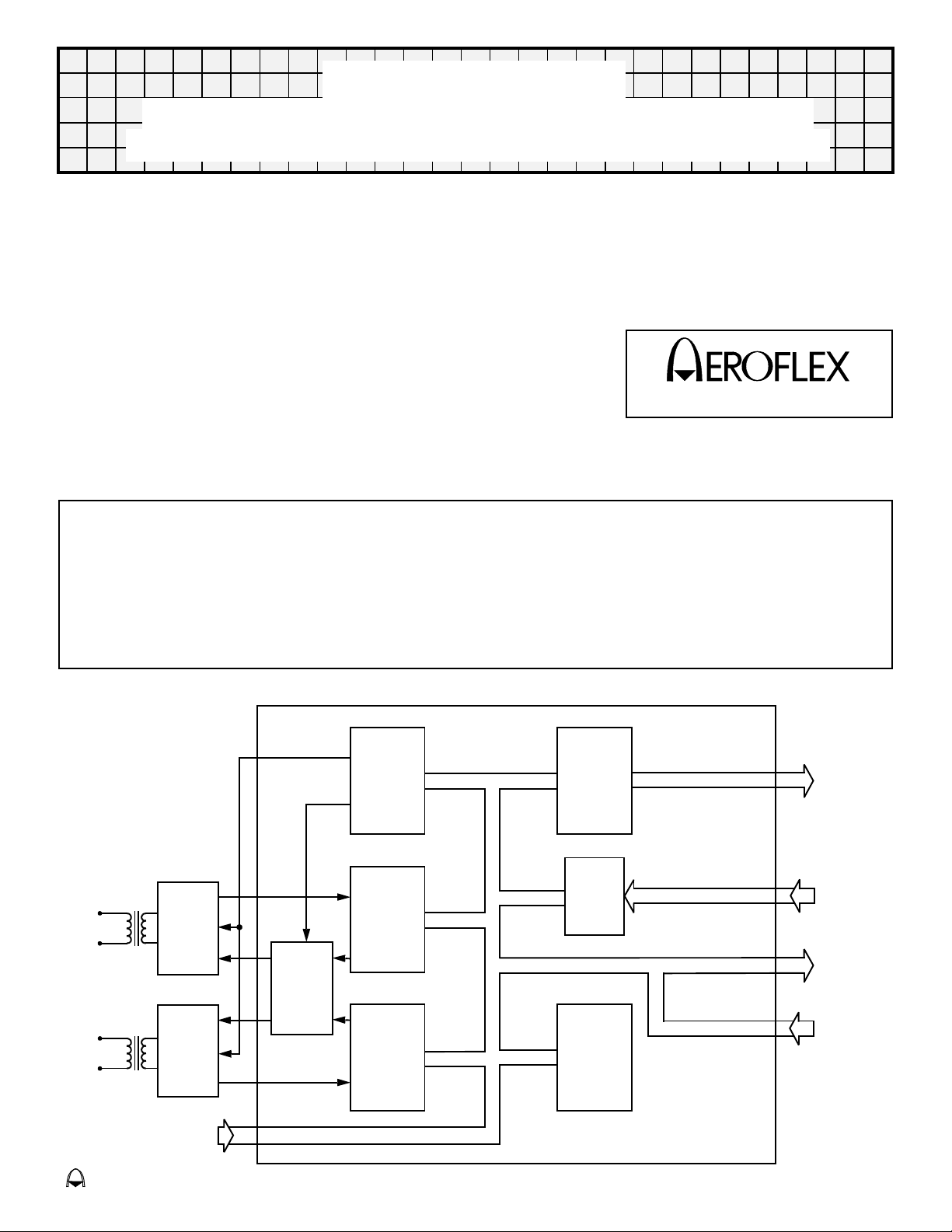
General Description
The CT1990/1 Series is a monolithic implementation of the MIL-STD-1553B Bus Controller, Remote
Terminal and Passive Monitor functions. All protocol functions of MIL-STD-1553B are incorporated and a
number of options are included to improve flexibility. These features include programming of the status
word, illegalizing specific commands and an independent loop back self-test which is initiated by the
subsystem. This unit is directly compatible with all transceivers and microprocessor interfaces such as the
CT1611 and CT1800 produced by Aeroflex Incorporated.
BUS "0"
BUS "1"
T/R
Hybrid
T/R
Hybrid
Terminal
Address
Inputs
Block Diagram (With Transformers)
Encoder
Decoder
"O"
Driver
Select
&
Enable
Decoder
"1"
Interface
Unit
Status
Word
Control
Internal
Highway
Control
CT1990/1
Sub Address
&
Word Count
Outputs
Program
Inputs
Discrete
Outputs
Control
Inputs
Page 2

Aeroflex Circuit Technology SCDCT1990 REV B 8/21/00 Plainview NY (516) 694-6700
Absolute Maximum Ratings
Parameter Range Units
Supply Voltage (VDD) -0.3 to +7.0 V
Input or Output Voltage at any Pad -0.3 to (V
Storage Case Temperature -65 to +150 °C
DD + 0.3) V
Recommended DC Operating Conditions
Parameter Min Typ Max Unit Notes
Vcc Power Supply Voltage Vcc 4.5
High Level Input Voltage, Vcc = 5V 2.2
V
IH
Low Level Input Voltage, Vcc = 5V 0.7 V 1,2
V
IL
5.0 5.5
V V
1,2
Electrical Characteristics
(TA = -55°C to +125°C)
Parameter Test Conditions Min Max Unit Notes
VOH High Level Output Voltage Vcc = 4.5V 2.4 V 4
Low Level Output Voltage Vcc = 4.5V 0.4 V 4
V
OL
High Level Input Current Vcc = 5.5V, VIN = 2.4V -200
I
IH
Low Level Input Current Vcc = 5.5V, VIN = 0.4V -400
I
IL
-25
-25
-700
-400
-900
-400
µA
µA
µA
µA
2
3
2
3
Supply Current Vcc = 5.5V 20 mA 4
I
CC
Notes:
1. RTAD 0/1/2/3/4 and RTADPAR ONLY.
2. ALL Inputs and Bidirectionals other than those in Note 1.
3. l
OL max = 3mA / lOH max = -2mA TX INHIBIT 0/1 and TX DATA/DATA ONLY. IOL max = 2mA / lOH max = -1 mA. ALL
remaining Outputs and Bidirectionals.
4. Input Clock (running) = 6Mhz, ALL remaining Inputs are Open and ALL Outputs and Bidirectionals have no load.
Clock Requirements
Frequency 6.0 MHz
Stability -55°C to +125°C ±0.01% (100ppm)
Maximum Asymmetry 48 - 52%
Rise/Fall Time 10ns MAX
Output Level Logic "0" 0.4V MAX
Logic "1" 2.4V MIN
2
Page 3

Aeroflex Circuit Technology SCDCT1990 REV B 8/21/00 Plainview NY (516) 694-6700
REMOTE TERMINAL OPERATION
Receive Data Operation
All valid data words associated with a valid receive data command word for the RT are passed to the subsystem.
The RT examines all command words from the bus and will respond to valid (i.e. correct Manchester, parity
coding etc.) commands which have the correct RT address (or broadcast address if the RT broadcast option is
enabled). When the data words are received, they are decoded and checked by the RT and, if valid, passed to
the subsystem on a word by word basis at 20 µs intervals. This applies to receive data words in both Bus
Controller to RT and RT to RT messages. When the RT detects that the message has finished, it checks that the
correct number of words have been received and if the message is fully valid, then a Good Block Received
signal is sent to the subsystem, which must be used by the subsystem as permission to use the data just
received.
The subsystem must therefore have a temporary buffer store up to 32 words long into which these data words
can be placed. The Good Block Received signal will allow use of the buffer store data once the message has
been validated.
If a block of data is not validated, then Good Block Received will not be generated. This may be caused by any
sort of message error or by a new valid command for the RT being received on another bus to which the RT
must switch.
Transmit Data Operation
If the RT receives a valid transmit data command addressed to the RT, then the RT will request the data words
from the subsystem for transmission on a word by word basis. To allow maximum time for the subsystem to
collect each data word, the next word is requested by the RT as soon as the transmission of the current word
has commenced.
It is essential that the subsystem should provide all the data words requested by the RT once a transmit
sequence has been accepted. Failure to do so will be classed by the RT as a subsystem failure and reported as
such to the Bus Controller.
Control of Data Transfers
This section describes the detailed operation of the data transfer mechanism between the RT and subsystems.
It covers the operations of the signals DTRQ
transmit data transfers.
Figure 7 shows the operation of the data handshaking signals during a receive command with two data words.
When the RT has fully checked the command word, NBGT
as an initialization signal. TX/RX
been fully validated, DTRQ
DTAK
low. This indicates to the RT that the subsystem is ready to accept data. The data word is then passed to
the subsystem on the internal highway IH08-IH715 in two bytes using IUSTB as a strobe signal and H/L
byte indicator (high byte first followed by low byte). Data is valid about both edges of IUSTB. Signal timing for
this handshaking is shown in Figure 12.
If the subsystem does not declare itself busy, then it must respond to DTRQ
within approximately 1.5 us. Failure to do so will be classed by the RT as a subsystem failure and reported as
such to the Bus Controller.
It should be noted that IUSTB is also used for internal working in the RT. DTRQ
enable for clocking data to the subsystem with IUSTB.
Once the receive data block has finished and been checked by the RT, GBR
correct and valid. This is used by the subsystem as permission to make use of the data block. If no GBR
is generated, then an error has been detected by the RT and the entire data block is invalid and no data words in
it may be used.
will be set low indicating a receive command. When the first data word has
is set low. The subsystem must then reply within approximately 1.5 µs by setting
, DTAK, IUSTB, H/L, GBR, NBGT, TX/RX during receive data and
is pulsed low, which can be used by the subsystem
as the
going low by setting DTAK low
being low should be used as an
is pulsed low if the block is entirely
signal
If the RT is receiving data in an RT to RT transfer, the data handshaking signals will operate in an identical
fashion but there will be a delay of approx 70 µs between NBGT
Figure 10.
3
going low and DTRQ first going low. See
Page 4

Aeroflex Circuit Technology SCDCT1990 REV B 8/21/00 Plainview NY (516) 694-6700
Figure 6 shows the operation of the data handshaking signals during transmit command with three data words.
As with the receive command discussed previously, NBGT
TX/RX
requests the first data word from the subsystem by setting DTRQ
approximately 13.5 µs by setting DTAK
word ready to pass to the RT. Once DTAK
and TX/RX
IH08-IH715. The RT will latch the data bytes during IUSTB, and will then return DTRQ
must remain stable until IUSTB has returned low. Signal timing for this handshaking is shown in Figure 11.
will be set high indicating a transmit data command. While the RT is transmitting its status word, it
low. By setting DTAK low, the subsystem is indicating that it has the data
is set low by the subsystem, DTRQ should be used together with H/L
to enable first the high byte and then the low byte of the data word onto the internal highway
is pulsed low if the command is valid and for the RT.
low. The subsystem must then reply within
high. Data for each byte
Additional Data Information Signals
At the same time as data transfers take place, a number of information signals are made available to the
subsystem. These are INCMD
word count lines CWC0-CWC4. Use of these signals is optional.
, the subaddress lines SA0-SA4, the word count lines WC0-WC4 and current
INCMD
transmit/receive bit, and word count from the command word are all made available to the subsystem as
SA0-SA4, TX/RX
valid while INCMD
The subaddress is intended to be used by the subsystem as an address pointer for the data block. Subaddress
0 and 31 are mode commands, and there can be no receive or transmit data blocks associated with these. (Any
data word associated with a mode command uses different handshaking operations. If the subsystem does not
use all the subaddresses available, then some of the subaddress lines may be ignored.
The TX/RX
described in the previous section.
The word count tells the subsystem the number of words to expect to receive or transmit in a message, up to 32
words. A word count of all 0s indicates a count of 32 words.
The current word count is set to 0 at the beginning of a new message and is incremented following each data
word transfer across the RT - subsystem interface. (It is clocked on the falling edge of the second IUSTB pulse
in each word transfer). It should be noted that there is no need for the subsystem to compare the word count and
current word count to validate the number of words in a message. This is done by the RT.
will go active low while the RT is servicing a valid command for the RT. The subaddress,
and WC0-WC4 respectively. They may be sampled when INCMD goes low and will remain
is low.
signal indicates the direction of data transfer across the RT - subsystem interface. Its use is
Subsystem Use of Status Bits and Mode Commands
General Description
Use of the status bits and the mode commands is one of the most confusing aspects of MIL-STD-1553B. This is
because much of their use is optional, and also because some involve only the RT while others involve both the
RT and the subsystem.
The CT1990/1 allows full use to be made of all the Status Bits, and also implements all the Mode Commands.
External programming of the Terminal Flag and Subsystem Flag Bits plus setting of the Message Error Bit on
reception of an illegal command when externally decoded is available. The subsystem is given the opportunity
to make use of Status Bits, and is only involved in Mode Commands which have a direct impact on the
subsystem.
The mode commands in which the subsystem may be involved are Synchronize, Sychronize with data word,
Transmit Vector Word, Reset and Dynamic Bus Control Acceptance. The Status Bits to which the subsystem
has access, or control are Service Request, Busy, Dynamic Bus Control Acceptance, Terminal Flag, Subsystem
Flag, and Message Error Bit. Operation of each of these Mode Commands and of the Status Bits is described in
the following sections.
All other Mode Commands are serviced internally by the RT. The Terminal Flag and Message Error Status Bits
and BIT Word contents are controlled by the RT; however the subsystem has the option to set the Message
Error Bit and to control the reset conditions for the Terminal Flag and Subsystem Flag Bits in the Status Word,
and the Transmitter Timeout, Subsystem Handshake, and Loop Test Fail Bits in the BIT Word.
4
Page 5

Aeroflex Circuit Technology SCDCT1990 REV B 8/21/00 Plainview NY (516) 694-6700
Synchronize Mode Commands
Once the RT has validated the command word and checked for the correct address, the SYNC line is set low.
The signal WC4 will be set low for a Synchronize mode command (See Figure 16), and high for a Synchronize
with data word mode command (See Figure 15). In a Synchronize with data word mode command, SYNC
remains low during the time that the data word is received. Once the data word has been validated, it is passed
to the subsystem on the internal highway IH08-IH715 in two bytes using IUSTB as a strobe signal and H/L as
the byte indicator (high byte first followed by low byte). SYNC being low should be used on the enable to allow
IUSTB to clock synchronize mode data to the subsystem.
If the subsystem does not need to implement either of these mode commands, the SYNC signal can be ignored,
since the RT requires no response from the subsystem.
Transmit Vector Word Mode Command
Figure 14 illustrates the relevant signal timings for an RT receiving a valid Transmit Vector Word mode
command. The RT requests data by setting VECTEN
byte and then the low byte of the Vector word onto the internal highway IH08-IH715.
It should be noted that the RT expects the Vector word contents to be already prepared in a latch ready for
enabling onto the internal highway when VECTEN
the Vector word mode command, it will be the fault of the Bus Controller if the RT receives such a command.
Since the subsystem is not required to acknowledge the mode command, the RT will not be affected in any way
by Vector word circuitry not being implemented in the subsystem. It will however transmit a data word as the
Vector word, but this word will have no meaning.
low. The subsystem should use H/L to enable first the high
goes low. If the subsystem has not been designed to handle
Reset Mode Command
Figure 8 shows the relevant signal timings for an RT receiving a valid reset mode command. Once the command
word has been fully validated and serviced, the RESET
signal is pulsed low. This signal may be used as a reset
function for subsystem interface circuitry.
Dynamic Bus Allocation
This mode command is intended for use with a terminal which has the capability of configuring itself into a bus
controller on command from the bus. The line DBCREQ
time of the valid command, i.e. tied low. For terminals acting only as RTs, the signal DBCACC
high (inactive), and the signal DBCREQ
should be ignored and left unconnected.
cannot go true unless the DBCACC line was true at the
should be tied
Use of the Busy Status Bit
The Busy Bit is used by the subsystem to indicate that it is not ready to handle data transfers either to or from
the RT.
The RT sets the bit to logic one if the BUSY
edge of INCLK after INCMD
goes low. This is shown in Figure 13. Once the Busy bit is set, the RT will stop all
receive and transmit data word transfers to and from the subsystem. The data transfers in the Synchronize with
data word and Transmit Vector word mode commands are not affected by the Busy bit and will take place even if
it has been set.
It should be noted that a minimum of 0.5 µs subaddress decoding time is given to the subsystem before setting
of status bits. This allows the subsystem to selectively set the Busy bit if for instance one subaddress is busy but
others are ready. This option will prove useful when an RT is interfacing with multiple subsystems.
line from the subsystem is active low at the time of the second falling
Use of the Service Request Status Bit
The Service Request bit is used by the subsystem to indicate to the Bus Controller that an asynchronous
service is requested.
The timing of the setting of this bit is the same as the Busy bit and is shown in Figure 13. Use of SERVREQ
no effect on the RT apart from setting the Service Request bit.
It should be noted that certain mode commands require that the last status word be transmitted by the RT
5
has
Page 6

Aeroflex Circuit Technology SCDCT1990 REV B 8/21/00 Plainview NY (516) 694-6700
instead of the current one, and therefore a currently set status bit will not be seen by the Bus Controller.
Therefore the user is advised to hold SERVREQ
low until the requested service takes place.
Use of the Subsystem Status Bit
This status bit is used by the RT to indicate a subsystem fault condition. If the subsystem sets SSERR low at
any time, the subsystem fault condition in the RT will be set, and the Subsystem Flag status bit will subsequently
be set. The fault condition will also be set if a handshaking failure takes place during a data transfer to or from
the subsystem. The fault condition is cleared on power-up or by a Reset mode command.
Dynamic Bus Control Acceptance Status Bit
DBCACC, when set true, enables an RT to configure itself into a Bus Controller, if the subsystem has the
capability, by allowing DBCREQ
Control is not required then DBCACC
TIME 18 in the status response.
to pulse true and BIT TIME 18 to be set in the status response. If Dynamic Bus
must be tied high. DBCACC tied high inhibits DBCREQ and clears BIT
OPTIONAL STATUS WORD CONTROL
Message Error Bit
The CT1990/1 monitors all receptions for errors and sets the Message Error Bit as prescribed in
MIL-STD-1553B. The subsystem designer may, however, exercise the option of monitoring for illegal commands
and forcing the Message Error Bit to be set.
The word count and subaddress lines for the current command are valid when INCMD
must then determine whether or not the word count or subaddress is to be considered illegal by the RT. If either
of them is considered illegal, the subsystem must produce a positive-going pulse called MEREQ. The
positive-going edge of MEREQ must occur within 500 ns of the falling edge of INCMD
goes low. The subsystem
.
Subsystem Flag and Terminal Flag Bits
The conditions that cause the Subsystem Flag and Terminal Flag Bits in the Status Word to be reset may be
controlled by the subsystem using the ENABLE
ENABLE
below: (i.e. the other three option lines are disabled).
Subsystem Flag Bit
This bit is reset to logic zero by a power up initialization or the servicing of a legal mode command to reset
the remote terminal (code 01000).
This bit shall be set in the current status register if the subsystem error line, SSERR
ever goes active low. This bit shall also be set if an RT/subsystem handshaking failure occurs. This bit,
once set, shall be repeatedly set until the detected error condition is known to be no longer present.
Terminal Flag Bit
This bit is reset to logic zero by a power up initialization or the servicing of a legal mode command to reset
the remote terminal (code 01000). This bit can be set to logic one in the current status register in four
possible ways:
This bit, once set, shall be repeatedly set until the detected error condition is known to be no longer
present. The transmission of this bit as a logic one can be inhibited a legal mode command to inhibit
terminal flag bit (code 00110). Similarly, this inhibit can be removed by a mode command to override inhibit
terminal flag bit (code 00111), a power up initialization or a legal mode command to reset remote terminal
(code 01000).
is inactive (high), then the Terminal Flag and Subsystem Flag behavior is the same as described
a) If the RX detects any message encoding error in the terminals transmission. A loop test failure,
LTFAIL, will be signalled which shall cause the Terminal Flag to be set and the transmission aborted.
b) If a transmitter timeout occurs while the terminal is transmitting.
c) If a remote terminal self test fails.
d) If there is a parity error in the hard wired address to the RX chip.
, BIT DECODE, NEXT STATUS, and STATUS UPDATE inputs. If
, from the subsystem
6
Page 7

Aeroflex Circuit Technology SCDCT1990 REV B 8/21/00 Plainview NY (516) 694-6700
If ENABLE is held low, then the three options described below are available and are essentially independent.
Any, all, or none may be selected. Also, reporting of faults by the subsystem requires that SSERR
(not pulsed) low until the fault is cleared.
be latched
Resetting SSF and TF on Receipt of Valid Commands
If ENABLE is selected and the other three option lines are held high, then the Status Word Register will be reset
on receipt of any valid command with the exception of Transmit Status and Transmit Last Command. Note that in
this mode, the TF will never be seen in the Status Word, and the SSF will only be seen if SSERR
Also note that the SSF will not be seen in response to Transmit Status or Transmit Last Command if the
preceding Status Word was clear, regardless of actions taken on the SSERR
transmission.
line after the clear status
is latched low.
Status Register Update at Fault Occurrence
If STATUS UPDATE is selected (held low), then the TF or SSF will appear in response to a Transmit Status or
Transmit Last Command issued as the first command after the fault occurs. Any other command (except as
noted in the Preserving the BIT Word section) will reset the TF and SSF. Repeated Transmit Status or Transmit
Last Command immediately following the fault will continue to show the TF and/or SSF in the Status Word. Note
that this behavior may not meet the "letter-of-the-spec" as described in MIL-STD-1553B, but is considered the
"preferred" behavior by some users.
TF and SSF Reporting in the Next Status Word
After the Fault
If NEXT STATUS is selected (held low), then the TF or SSF will appear in response to the very next valid
command after the fault except for Transmit Status or Transmit Last Command. The flag(s) will be reset on
receipt of any valid command following the status transmission with the flag(s) set except for Transmit Status,
Transmit Last Command, or as noted in the following section on Preserving the BIT Word.
Preserving the BIT Word
In order to preserve the Transmitter Timeout Flag, Subsystem Handshake Failure, and Loop Test Failure Bits in
the BIT Word, it is necessary to select BIT DECODE
Transmit Bit Word Mode Command immediately follows the fault or follows a Transmit Last Command or
Transmit Status immediately following the fault. It will also prevent resetting the TF and SSF Bits in the Status
Word. Any other valid commands will cause those BIT Word Bits and the Status Word Bits to be reset.
(hold it low). This will prevent resetting those bits if the
Bus Driver/Receiver Interface
Receive Data
The decoder chip requires two TTL signals, RXDATA and RXDATA, to represent the data coming in from the bus.
PDIN should be driven to a logic level ‘1’ when the bus waveform exceeds a specified positive threshold and
NDIN should be driven to a logic level ‘1’ when a specified negative threshold is exceeded. During the quiet
period on the bus both signals should be at the same logic level. All the bus receivers must be permanently
enabled, the selection of the bus in use is controlled within the ASIC.
Transmit Data
The signals generated by the encoder chip, TXDATA and TXDATA, are of the same format as the receive data.
The only difference is that the TTL signals are negative logic, e.g. the signal is active when on logic level "0".
This means that when the encoder is quiet both TXDATA and TXDATA
should be used in conjunction with TXINHIBIT 0 and TXINHIBIT 1. TX INHIBIT 0 and TX INHIBIT 1 enable the
appropriate driver when it should be transmitting. Figure 5 shows an example of a typical interface circuit
between the CT1990/1 and a driver/receiver unit.
7
are at logic level "1". Both the signals
Page 8

Aeroflex Circuit Technology SCDCT1990 REV B 8/21/00 Plainview NY (516) 694-6700
BUS CONTROL OPERATION
To enable its use in a bus controller the ASIC has additional logic within it. This logic can be enabled by pulling
the pin labelled RT/BC
control processor correctly commanding the ASIC via the subsystem interface. In bus control mode six inputs
are activated which in RT mode are inoperative and four signals with dual functions exercise the second function
(the first being for the RT operation).
To use the CT1990/1 as a 1553B bus control interface, the bus control processor must be able to carry out four
basic bus-related functions. Two inputs, BCOPA and BCOPB allow these four options to be selected. The option
is then initiated by sending a negative-going strobe on the BCOPSTB
low when NDRQ
With these options all message types and lengths can be handled. Normal BC/RT exchanges are carried out in
ASIC option zero. This is selected by setting BCOPA and BCOPB to a zero and strobing BCOPSTB
of the strobe, the CT1990/1 loads the command word from an external latch using CWEN and H/L The
command word is transmitted down the bus. The TX/RX
inverse and so if a transmit command is sent to a RT (Figure 17), the ASIC in BC mode believes it has been
given a receive command. As the RT returns the requested number of data words plus its status, the BC carries
out a full validation check and passes the data into the subsystem using DTRQ
in RT operation. It also supplies GBR
down the bus is interpreted by the BC as a transmit command, and so the requisite data words are added to the
command word. See Figure 18.
For mode commands, where a single command word is required, option one is selected by strobing BCOPSTB
when BCOPA is high and BCOPB is low. On receiving the strobe, the command word is loaded from the external
latch using CWEN
Mode commands followed by a data word requires option two. Option two, selected by strobing BCOPSTB
BCOPA is low and BCOPB is high, loads a data word via DWEN
them to the bus (See Figure 21). If the mode code transmitted required the RT to return a data word, then
selecting option three by strobing BCOPSTB
and if validated, output it to the subsystem interface using RMDSTB and H/L.
from mode codes to be identified differently from ordinary data words and routed accordingly (See Figure 22).
All received status words are output to the subsystem interface using STATSTB and H/L
low. Once the ASIC is in bus control mode, all data transfers must be initiated by the bus
input. BCOPSTB must only be strobed
is high. This is particularly important when two options are required during a single transfer.
. On receipt
bit is, however, considered by the ASIC as being its
, DTAK, H/L, IUSTB and CWC as
at the end of a valid transmission. Conversely, a receive command sent
and H/L, the correct sync and parity bits are added and the word transmitted (See Figure 20).
while
and H/L, adds sync and parity and transmits
when BCOPA and BCOPB are both high will identify that data word
This allows data words resulting
.
In BC option three, if the signal PASMON
subsystem using STATSTB for command and status words or RMDSTB for data words.
RT to RT transfers require the transmission of two command words. A receive command to one RT is
contiguously followed by a transmit command to the other RT. This can be achieved by selecting option one
followed by option zero for the second command. The strobe (BCOPSTB
NDRQ
and transferred in the subsystem interface to the bus control processor (See Figure 19).
Note: For all BC operations, BCOPA and BCOPB must remain valid and stable for a minimum of 1 µs following
the leading (negative going) edge of BCOPSTB
has gone low and returned high following the strobe for option one. The RT transmissions are checked
is active, then all data appearing on the selected bus is output to the
) for option zero must be delayed until
.
PASSIVE MONITOR
The Monitor Mode may be utilized to analyze or collect all activities which occur on a selected bus. This is
initiated by selecting a bus, placing the unit in BC option three and setting PASMON
the selected bus is output to the subsystem using STATSTB for Command and Status Words or RMDSTB for
Data Words.
low. All data appearing on
8
Page 9

Aeroflex Circuit Technology SCDCT1990 REV B 8/21/00 Plainview NY (516) 694-6700
AUTOMATED SELF-TEST
The CT1991 has been designed to fully support a wrap-around self-test which ensures a high degree of fault
coverage. The monolithic circuit includes all circuitry required to perform the self-test.
Self-test can be an on-line or off-line function which is initiated by simple subsystem intervention. The DRVINH
signal selects on-line or off-line testing. The circuit accomplishes the on-line test without accessing the
MIL-STD-1553 data bus by providing an internal data path which connects the encoder circuitry directly to the
decoder circuitry. The transceiver is inhibited during this on-line test. The off-line test is designed to include the
transceiver as well as the protocol device. This mode will generally be useful as an off-line card test where no
live bus is in use.
To initiate the self-test a word is placed in the Vector Word Latch, Loop Test Enable (LTEN
Loop Test Trigger (LTTRIG
Vector Word Latch, encoded then looped back, decoded and presented to the subsystem as a normal data
transfer would be accomplished. The secondary bus is sequentially tested after the primary bus is completed
via Request Bus A (REQBUSA) utilizing the same word residing in the Vector Word Latch. Upon completion of
each test, pass/fail signals will be asserted reporting the results of the test. This test implementation verifies
MIL-STD-1553 protocol compliance; proper sync character, 16 data bits, Manchester II coding, odd parity,
contiguous word checking and a bit by bit comparison of the transmitted data. The self-test circuitry increases
the fault coverage by insuring that the internal function blocks; encoder, decoder, and internal control circuitry
are operating correctly. An effective data pattern to accomplish this is HEX AA55 since each bit is toggled, (8 bit
internal highway) on a high/low byte basis. The total time required to complete the self-test cycle is 89
microseconds. The Loop Test Enable signal must remain in the low state throughout the diagnostic cycle.
) signal is pulsed low. The primary bus will be tested with the word that resides in the
) is held low, and the
9
Page 10

Aeroflex Circuit Technology SCDCT1990 REV B 8/21/00 Plainview NY (516) 694-6700
Pin Description
Signal Direction Signal Description
RX DATA 0/1 INPUT Positive Data In. This should be a TTL description of the positive, half of the
Manchester code data on the bus. It should be driven to a logic level “1” when
a predetermined positive threshold is exceeded on the bus.
RX DATA
TX INHIBIT 0 OUTPUT Transmitter Inhibit Bus 0. Normally high. Goes low when the transmitter is
TX INHIBIT 1 OUTPUT Transmitter Inhibit Bus 1. Normally high. Goes low when the transmitter is
TX DATA OUTPUT Positive Data Out - When this signal goes high the bus should be driven
TX DATA
RTAD 0-4 INPUT RT address lines - These should be hardwired by the user. RTAD4 is the most
RTADPAR INPUT RT address parity line - This must be hardwired by the user to give odd parity.
BIT DECODE
BCSTEN 0/1 INPUT Broadcast command enable Bus 0/1 - When low the recognition of
BCSTEN 0 INPUT Broadcast command enable Bus 0 - When low the recognition of broadcast
0/1 INPUT Negative Data In. This should be a TTL description of the negative half of the
Manchester code data on the bus. It should be driven to a logic level “1” when
a predetermined negative threshold is exceeded on the bus.
transmitting. Should be used to Inhibit the bus "0" driver.
transmitting. Should be used to Inhibit the bus "1" driver.
positive.
OUTPUT Negative Data Out - When this signal goes high the bus should be driven
negative.
significant bit.
INPUT Built-ln Test Decode - When held low, prevents resetting TXTO Bit, HSFAIL
Bit, and LTFAIL Bit in the BIT Word (as well as TF and SSF Bits in the Status
Word) upon receipt of a Transmit Bit Word Mode Command.
broadcast command is prevented on both Bus 0 and 1. CT1991 only.
command is prevented on Bus 0. CT1990 only.
BCSTEN 1 INPUT Broadcast command enable Bus 1 - When low the recognition of broadcast
command is prevented on Bus 1. CT1990 only.
6MCK INPUT 6 Megahertz master clock.
IH 08 (LSB)
IH 19
IH 210
IH 311
IH 412
IH 513
IH614
IH715 (MSB)
DTRQ
DTAK
IUSTB OUTPUT Interface Unit Strobe - This is a double pulse strobe used to transfer the two
H/L
GBR
BI-DIRECTIONAL Internal Highway - Bi-directional 8 bit highway on which 16 bit words are
passed in two bytes. IH 715 is the most significant bit of each byte, the most
significant byte being transferred first. The highway should only be driven by
the subsystem when data is to be transferred to the RT.
OUTPUT Data Transfer Request - Goes low to request a data transfer between the
ASIC and subsystem. Goes high at the end of the transfer.
INPUT Data Transfer Acknowledge - Goes low to indicate that the subsystem is
ready for the data transfer.
bytes of data
OUTPUT High/Low - Indicates which byte of data is on the internal highway. Logic level
"0" for least significant byte.
OUTPUT Good Block Received - Pulses low for 500ns when a block of data has been
received by the ASIC and has passed all the validity and error checks.
10
Page 11

Aeroflex Circuit Technology SCDCT1990 REV B 8/21/00 Plainview NY (516) 694-6700
Pin Description (Cont.)
Signal Direction Signal Description
NBGT OUTPUT New Bus Grant - Pulses low whenever a new command is accepted by the
ASIC.
MEREQ INPUT Message Error Request - Positive-going edge will cause Message Error Bit in
Status Word to be set.
TX/RX
INCMD
WC0-WC4 OUTPUT Word Count - These five lines specify the requested number of data words to
SA0-SA4 OUTPUT Sub Address - These five lines are a label for the data being transferred. Valid
CWC0-CWC4 OUTPUT Current Word Count - These five lines define which data word in the message
SYNC
VECTEN
RESET
SSERR
/DWEN OUTPUT Vector Word Enable/DataWord Enable - In the RT mode, this signal is
OUTPUT Transmit/Receive - The state of this line informs the subsystem whether it is
to transmit or receive data The signal is valid while INCMD
OUTPUT In Command - Goes low when the RT is servicing a valid command. The
subaddress and word count lines are valid while the signal is low.
be received or transmitted. Valid when INCMD
when INCMD is low.
is currently being transferred.
OUTPUT Synchronize - Goes low when a synchronize mode code is being serviced.
provided to enable the contents of the vector word latch (which is situated in
the subsystem) onto the ASIC’s internal highway. This signal, when in the Bus
Controller mode, is used to enable mode code data from the subsystem onto
the internal highway.
OUTPUT Reset - This line pulses low for 500ns on completion of the servicing of a valid
and legal mode command to reset remote terminal.
INPUT Subsystem Error - By taking this line low, the subsystem can set the
Subsystem Flag in the Status Word.
is low.
is low.
BUSY
SERVREQ
INCLK OUTPUT Internal Clock (2 MHz) - This is made available for synchronization use by the
EOT
RTADER
HSFAIL
LSTCMD
/CWEN OUTPUT Last Command/Command Word Enable - This line pulses low when
INPUT Busy - This signal should be driven low if the subsystem is not ready to
perform a data transfer to or from the ASIC.
INPUT Service Request - This signal should be driven low to request an
asynchronous transfer and left low until the transfer has taken place.
subsystem if required. However, many of the outputs to the subsystem are
asynchronous.
OUTPUT End of Transmission - Goes low if a valid sync plus two data bits do not
appear in time to be contiguous with preceding word.
OUTPUT Remote Terminal Address Error - This line goes low if an error is detected in
the RT address parity of the selected receiver. Any receiver detecting an error
in the RT address will turn itself off.
OUTPUT Handshake Failure - This line pulses low if the allowable time for DTAK
response has been exceeded during the ASIC/subsystem data transfer
handshaking.
servicing a valid and legal mode command to transmit last command. When in
RT mode this line must not be used to enable data from the subsystem. This
line also pulses low, when in the Bus Control mode, when a command word is
required for transmission.
11
Page 12

Aeroflex Circuit Technology SCDCT1990 REV B 8/21/00 Plainview NY (516) 694-6700
Pin Description (Cont.)
Signal Direction Signal Description
STATEN/
STATSTB
STAT UPDATE
/
BITEN
RMDSTB
DWSYNC
ENABLE
CMSYNC
NDRQ
OUTPUT Status Enable/Status Strobe - This line pulses low to enable the status word
onto the internal highway for transmission. When in RT mode this line must not
be used to enable data from the subsystem. This line also pulses high, when in
the Bus Control mode, to strobe received status words into the subsystem.
When PASMON
INPUT Status Update - When held low, causes TF or SSF to appear in Status Word
response to Transmit Status or Transmit Last Command issued immediately
after fault occurrence
OUTPUT Built In Test Enable/Receive Mode Data Strobe - This line pulses low when
servicing a valid and legal mode command to transmit the internal BIT word.
This signal is for information only and must not be used to enable data from the
subsystem. This line also pulses high when in the Bus Control mode when
mode data is received to be passed to the subsystem and when data is passed
to the subsystem during PASMON
OUTPUT Data Word Sync - This line goes low if a data word sync and two Manchester
biphase bits are valid. CT1990 only.
INPUT Enable - When held low, enables Bit Decode, Next Status, and Status Update
program lines.
OUTPUT Command Word Sync - This line goes low if a command word sync and two
Manchester biphase bits are valid. CT1990 only.
OUTPUT No Data Required - This line goes low if the encoder transmit buffer is full i.e.
another word is going to be transmitted. This signal is for information only and
must not be used to enable data from the subsystem.
is true this line pulses high for Command and Status words.
.
NEXT STAT
PASMON
BCOPSTB
RMDSTB See BITEN
BCOPA INPUT Bus Control Operation A - Least significant bit of the bus controller operation
BCOPB INPUT Bus Control Operation B - Most significant bit of the bus controller operation
REQBUS A BI-DIRECTIONAL Request Bus A - This line, when in RT mode, is the least significant bit of the
INPUT Next Status - When held low, causes TF or SSF to appear in very next Status
Word after fault occurrence (except for Transmit Status or Transmit Last Com-
mand).
INPUT Passive Monitor - When functioning as a Bus Controller this line acts as a
passive monitor select. The active going edge of this line will cause the
REQBUS lines to be latched and that bus, now selected will be monitored so
long as PASMON
validation, to the subsystem via STATSTB for status and commands words,
and RMDSTB for data words.
INPUT Bus Controller Operation Strobe - When functioning as a Bus Controller a
low going pulse on this line will initiate the selected bus controller operation on
the requested bus, using BCOPA&B and REQBUSA&B.
select lines.
select lines.
bus request lines which specify the origin of the command, i.e. they are
sources. When in BC mode these lines are sinks and specify which bus is to be
used for the next command.
remains low. All traffic on the bus will be handed, after
/RMDSTB.
REQBUS B BI-DIRECTIONAL Request Bus B - Most significant bit of the bus request lines. (See above for
description.)
12
Page 13

Aeroflex Circuit Technology SCDCT1990 REV B 8/21/00 Plainview NY (516) 694-6700
Pin Description (Cont.)
Signal Direction Signal Description
RT/BC INPUT Remote Terminal/Bus Control - This line when high causes the ASIC to
function as a remote terminal. When low the ASIC functions as a bus controller
or passive monitor.
DBCACC
LTFAIL
ERROR
RTO
TXTO
PARER
MANER
DBCREQ
VALD
DRVINH
INPUT Dynamic Bus Control Accept - This line should be permanently tied low if a
subsystem is able to accept control of the bus if offered.
OUTPUT Loop Test Fail - This line goes low if any error in the transmitted waveform is
detected or if any parity error in the hardwired RT address is detected.
OUTPUT Error - This line latches low if a Manchester or parity error is detected. It is
reset by the next CMSYNC
OUTPUT Reply Time Out - This signal will pulse low whenever the reply time for a
transmitting terminal has been exceeded. This line is intended for the bus
controller use.
OUTPUT Transmitter Time Out - This line goes true if the transmitter time out limits are
exceeded.
OUTPUT Parity Error - This line will pulse low if a parity error is detected by the
decoder.
OUTPUT Manchester Error - This line will pulse low if a Manchester error is detected by
the decoder.
OUTPUT Dynamic Bus Control Request - This line will pulse low when the status reply
for a mode code Dynamic Bus Control has finished where the accept bit was
set.
OUTPUT Valid Data - This line will pulse low when a valid data word is received.
INPUT Driver Inhibit - Selects on-line or off-line testing during automated self test.
When high self test is on-line. Must be high when LTEN
(RT mode) and also by RTO in the BC mode.
is high. CT1991 only.
LTEN
LTTRIG
INPUT Loop Test Enable - Enables automated self-test when low. Normally high.
CT1991 only.
INPUT Loop Test Trigger - When pulsed low while LTEN is low automated self-test is
initiated. LTEN
pulse width should be 100ns < PW < 5µs. CT1991 only.
13
Page 14

Aeroflex Circuit Technology SCDCT1990 REV B 8/21/00 Plainview NY (516) 694-6700
Controller to
RT Transfer
Receive
Command
Data
Word
Data
Word
. . . .
Data
Word
. .
Status
Word
§ Command
NEXT
Word
RT to
Controller
Transfer
RT to RT
Transfer
Mode Command
Without Data
Word
Mode Command
With Data
Word
(Transmit)
Mode Command
With Data
Word
(Receive)
Transmit
Command
Receive
Command
Mode
Command
Mode
Command
Mode
Command
. .
Transmit
Command
. .
. .
Data
Word
Status
Word
. .
Status
Word
Status
Word
. .
Data
Word
Status
Word
§ Command
Data
Word
Status
Word
Data
Word
Data
Word
NEXT
Word
. . . .
Data
Word
NEXT
§ Command
Word
NEXT
§ Command
Word
Data
Word
. . . .
§ Command
Data
Word
NEXT
Word
. .
NOTE: § = Intermessage Gap
Status
Word
. . = Response Time
Figure 1 – Typical Message Formats
T/R
Bit
Mode Code Function
1 00000 Dynamic Bus Control No No
Associated
Data Word
Broadcast Command
Allowed
NEXT
§ Command
Word
1 00001 Synchronize No Yes
1 00010 Transmit Status Word No No
1 00011 Initiate Self Test No Yes
1 00100 Transmitter Shutdown No Yes
1 00101 Override Transmitter Shutdown No Yes
1 00110 Inhibit Terminal Flag Bit No Yes
1 00111 Override lnhibit Terminal Flag Bit No Yes
1 01000 Reset Remote Terminal No Yes
1 01001 Reserved No TBD
↓ ↓ ↓ ↓
1 01111 Reserved No TBD
1 10000 Transmit Vector Word Yes No
0 10001 Synchronize Yes Yes
1 10010 Transmit Last Command Yes No
1 10011 Transmit BlTWord Yes No
0 10100 Selected Transmitter Shutdown Yes Yes
0 10101 Override Selected Transmitter
Yes Yes
Shutdown
1 or 0 10110 Reserved Yes TBD
↓ ↓ ↓ ↓
1 or 0 11111 Reserved Yes TBD
Figure 2 – Assigned Mode Codes
14
Page 15

Aeroflex Circuit Technology SCDCT1990 REV B 8/21/00 Plainview NY (516) 694-6700
BIT TIMES 1 2 3 4 5 6 7 8 9 10 11 12 13 14 15 16 17 18 19 20
Transmitter Timeout on Bus 3
Transmitter Timeout on Bus 2
Transmitter Timeout on Bus 1
Transmitter Timeout on Bus 0
Bus 3 Shutdown
Bus 2 Shutdown
Bus 1 Shutdown
Bus 0 Shutdown
Broadcast Transmit Data Received
Word Count High
Word Count Low
Illegal Mode Command
Mode T/R Bit Wrong
Loop Test Failure
Subsystem Handshake Failure
Transmitter Timeout Flag
Message Error
Instrumentation
Service Request
Broadcast Command Received
Busy
Subsystem Flag
Dynamic Bus Control Acceptance
Terminal Flag
Parity
COMMAND
WORD
SYNC
DATA WORD 16 1
1 LSB 20
BIT WORD 15 14 13 12 11 10 9 8 7 6 5 4 3 2 1 0 P
SYNC
REMOTE TERMINAL
5 1 5 5 1
DATA WORD
COUNT/MODE CODE
ADDRESS
T/R SUBADDRESS/MODE
DATA P
P
STATUS WORD 5 1 1 1 3 1 1 1 1 1 1
SYNC REMOTE TERMINAL
ADDRESS
Note: T/R – Transmit/Receive
P – Parity
Figure 3 – Word Count
15
RESERVED
Page 16

Aeroflex Circuit Technology SCDCT1990 REV B 8/21/00 Plainview NY (516) 694-6700
1MHz
=
Clock
One Bit Time
(+) (0) -
+
1553B
BUS "A"
Manchester
TX DATA OUT
RX DATA IN
XFR0
TX DATA
RX DATA
OUT
IN
NRZ
Data
Bi-Phase
(+) (0) -
(+) -
(0) -
(-) -
ACT4453
Driver/
Receiver 0
Figure 4 – Data Encoding
RX DATA OUT
RX DATA
TX DATA
TX DATA IN
OUT
IN
CT1990/1
RX DATA 0
RX DATA
TX DATA
TX DATA
0
TX INHIBIT "0"
+
1553B
TX DATA OUT
RX DATA IN
ACT4453
RX DATA OUT
RX DATA
OUT
RX DATA 1
RX DATA
1
BUS "B"
Driver/
TX DATA IN
Receiver 1
TX DATA
IN
TX INHIBIT "0"
XFR1
TX DATA
RX DATA
OUT
IN
TX INHIBIT "1"
TX INHIBIT "1"
Figure 5 – Example of an Interface between the CT1990/1 and Driver/Receiver
16
Page 17

Aeroflex Circuit Technology SCDCT1990 REV B 8/21/00 Plainview NY (516) 694-6700
PDIN
NBGT
INCMD
DTRQ
IUSTB
H/L
GBR
EOT
Figure 6 – Transfer of three Data Words from RT 03 to BC
PDIN
NBGT
INCMD
DTRQ
IUSTB
H/L
GBR
EOT
Figure 7 – Transfer of two Data Words from BC to RT 03
PDIN
NBGT
INCMD
DTRQ
IUSTB
H/L
RESET
EOT
Figure 8 – Mode Command Reset Remote Terminal
17
Page 18

Aeroflex Circuit Technology SCDCT1990 REV B 8/21/00 Plainview NY (516) 694-6700
PDIN
NBGT
INCMD
DTRQ
IUSTB
H/L
GBR
EOT
Figure 9 – RT to RT transfer of four data words
(This RT sending the data)
PDIN
NBGT
INCMD
DTRQ
IUSTB
H/L
GBR
EOT
Figure 10 – RT to RT transfer of four data words
(This RT receiving the data)
18
Page 19

Aeroflex Circuit Technology SCDCT1990 REV B 8/21/00 Plainview NY (516) 694-6700
DTRQ
Subsystem Reply Time < 13.5µs
DTAK
IUSTB
H/L
CWC0-CWC4
250 nsec
500 nsec
Valid Incremented
Enable High Byte of TX
Data on Internal
Highway
Enable Low Byte of
TX Data on Internal
Highway
Figure 11 – Handshaking for Tx Data Transfers
Don’t Care
250 nsec
DTRQ
DTAK
IUSTB
H/L
Internal
Highway
CWC0-CWC4
Subsystem Reply Time < 1.5µs
250 nsec
High Byte Valid
Don’t Care
250 nsec
500 nsec
Low Byte Valid
IncrementedValid
Figure 12 – Handshaking for Rx Data Transfers
19
Page 20

Aeroflex Circuit Technology SCDCT1990 REV B 8/21/00 Plainview NY (516) 694-6700
NBGT
}
}
1.0µs Minimum
TX/RX
SA4-SA0
WC4-WC0
CWC4-CWC0
INCMD
INCLK
Previous command value
Previous command value
Previous command value
Figure 13 – New Command Initialization
Valid
Valid
Valid
BUSY
Latch here
NBGT
INCMD
VECTEN
H/L
Enable high byte of
vector word onto
internal highway
Figure 14 – Transmit Vector Word Command
1.5µs
approx.
Enable low byte of
vector word onto
internal highway
20
Page 21

Aeroflex Circuit Technology SCDCT1990 REV B 8/21/00 Plainview NY (516) 694-6700
PDIN
NBGT
INCMD
SYNC
ILUSTB
EOT
WC4
H/L
0 0
1
1
0
1
0
1
0
1
0
1
0
1
0
1
0
Figure 15 – Synchronize (with data) mode command
PDIN
NBGT
INCMD
SYNC
IUSTB
EOT
WC0
1
0 0
1
0
1
0
1
0
1
0
1
0
1
0
Figure 16 – Synchronize (no data) mode command
21
Page 22

Aeroflex Circuit Technology SCDCT1990 REV B 8/21/00 Plainview NY (516) 694-6700
BCOPSTB
NDRG
CWEN
H/L
IUSTB
C/D
NBGT
INCMD
VALC
VALD
STATSTB
DTRG
GBR
EOT
RTO
PDIN
Figure 17 – BUS Controller sending command to RT 10001 to transmit two data words
22
Page 23

Aeroflex Circuit Technology SCDCT1990 REV B 8/21/00 Plainview NY (516) 694-6700
BCOPSTB
NDRG
CWEN
H/L
IUSTB
C/D
NBGT
INCMD
VALC
VALD
STATSTB
DTRG
GBR
EOT
RTO
PDIN
Figure 18 – BUS Controller sending command to RT 10001 to receive two data words
23
Page 24

Aeroflex Circuit Technology SCDCT1990 REV B 8/21/00 Plainview NY (516) 694-6700
BCOPSTB
BCOPA
BCOPB
NDRG
CWEN
H/L
IUSTB
C/D
TxSTB
NBGT
INCMD
VALC
VALD
STATSTB
DTRG
CWC0
CWC1
TREQ
GBR
EOT
TXEN
PDOUT
RTO
IH715
IH614
IH613
IH412
IH311
IH210
IH19
IH06
PDIN
Figure 19 – BUS Controller commanding RT 10001 to transmit two data words at RT 00001
24
Page 25

Aeroflex Circuit Technology SCDCT1990 REV B 8/21/00 Plainview NY (516) 694-6700
BCOPSTB
BCOPA
BCOPB
PDIN
TXSTB
CWEN
H/L
STATSTB
Figure 20 – BUS Controller sending mode command transmit
status word mode code 00010
BCOPSTB
BCOPA
BCOPB
PDIN
NDRQ
CWEN
DWEN
H/L
BCOPSTB
BCOPA
BCOPB
PDIN
DWEN
H/L
STATSTB
RMDSTB
Figure 21 – BUS Controller sending mode command
synchronize mode code 10001
Figure 22 – BUS Controller sending mode command transmit
vector mode code 10000
25
Page 26

Aeroflex Circuit Technology SCDCT1990 REV B 8/21/00 Plainview NY (516) 694-6700
Pin Out Description - CT1990
Pin # Function Pin # Function Pin # Function
1 BIT DECODE 31 REQBUSB 61 ERROR
2 CWC0 (LSB) 32 REQBUSA 62 LTFAIL
3 SA4 (MSB) 33 COMMON & CASE 63 MANER
4 SA3 34 ENABLE 64 PARER
5 SA2 35 STAT UPDATE 65 VALD
6 CWC4 (MSB) 36 MEREQ 66 RTADER
7 CWC3 37 IH 08 (LSB) 67 RX DATA 1
8 CWC2 38 IH19 68 RX DATA
9 CWC1 39 IH210 69 +5 VIN
10 GBR
11 H/L
12 STATEN
13 EOT
14 SA1 44 IH715 (MSB) 74 SERVREQ
15 SA0 (LSB) 45 NC 75 TXTO
16 INCMD 46 NC 76 DBCACC
17 TX/RX 47 RTADPAR 77 RESET
18 DTRQ 48 RTAD0 (LSB) 78 RT/BC
19 VECTEN/DWEN 49 RTAD1 79 DBCREQ
20 NBGT 50 RTAD2 80 HSFAIL
21 SYNC 51 RTAD3 81 LSTCMD/CWEN
/STATSTB 42 IH513 72 TX DATA
40 IH311 70 TX INHIBIT 1
41 IH412 71 TX INHIBIT 0
43 IH614 73 TX DATA
1
22 INCLK 52 RTAD4 (MSB) 82 BITEN/RMDSTB
23 IUSTB 53 CMSYNC 83 BUSY
24 NEXT STAT 54 DWSYNC 84 WC4 (MSB)
25 DTAK
26 BCOPA 56 RX DATA 0 86 WC0 (LSB)
27 BCOPSTB
28 BCOPB 58 BCSTEN 1 88 WC2
29 PASMON
30 NDRQ
55 BCSTEN 0 85 WC3
57 RX DATA 0 87 SSERR
59 RTO 89 WC1
60 6 MCK 90 NC
26
Page 27

Aeroflex Circuit Technology SCDCT1990 REV B 8/21/00 Plainview NY (516) 694-6700
Pin Out Description - CT1991
Pin # Function Pin # Function Pin # Function
1 BIT DECODE 31 REQBUSB 61 ERROR
2 CWC0 (LSB) 32 REQBUSA 62 LTFAIL
3 SA4 (MSB) 33 COMMON & CASE 63 MANER
4 SA3 34 ENABLE 64 PARER
5 SA2 35 STAT UPDATE 65 VALD
6 CWC4 (MSB) 36 MEREQ 66 RTADER
7 CWC3 37 IH 08 (LSB) 67 RX DATA 1
8 CWC2 38 IH19 68 RX DATA
9 CWC1 39 IH210 69 +5 VIN
10 GBR
11 H/L
12 STATEN
13 EOT
14 SA1 44 IH715 (MSB) 74 SERVREQ
15 SA0 (LSB) 45 NC 75 TXTO
16 INCMD 46 NC 76 DBCACC
17 TX/RX 47 RTADPAR 77 RESET
18 DTRQ 48 RTAD0 (LSB) 78 RT/BC
19 VECTEN/DWEN 49 RTAD1 79 DBCREQ
20 NBGT 50 RTAD2 80 HSFAIL
21 SYNC 51 RTAD3 81 LSTCMD/CWEN
/STATSTB 42 IH513 72 TX DATA
40 IH311 70 TX INHIBIT 1
41 IH412 71 TX INHIBIT 0
43 IH614 73 TX DATA
1
22 INCLK 52 RTAD4 (MSB) 82 BITEN/RMDSTB
23 IUSTB 53 LTEN 83 BUSY
24 NEXT STAT 54 LTTRIG 84 WC4 (MSB)
25 DTAK
26 BCOPA 56 RX DATA 0 86 WC0 (LSB)
27 BCOPSTB
28 BCOPB 58 DRVINH 88 WC2
29 PASMON
30 NDRQ
55 BCSTEN 0/1 85 WC3
57 RX DATA 0 87 SSERR
59 RTO 89 WC1
60 6 MCK 90 NC
27
Page 28

Aeroflex Circuit Technology SCDCT1990 REV B 8/21/00 Plainview NY (516) 694-6700
Ceramic CoFired Plug In Package Outline
Lead 1 & ESD
Designator
.135
1.300
.090
Pin 1
1.100
Pin 3
Pin 2
2.400
MAX
2.200
.050
TYP
Pin 43
1.600
MAX
Pin 45
Pin 44
.018 DIA
TYP
.225
MAX
.200
MIN
Pin 90
.135
Pin 89
Pin 88
.100
TYP
2.100
Pin 48
Pin 47
Pin 46
28
Page 29

Aeroflex Circuit Technology SCDCT1990 REV B 8/21/00 Plainview NY (516) 694-6700
CIRCUIT TECHNOLOGY
Ordering Information
Model Number DESC Part Number Package
CT1990-1-20
CT1991-1-20
5962-9477501 1.6" x 2.4" Ceramic Plug In
Pending 1.6" x 2.4" Ceramic Plug In
Aeroflex Circuit Technology
35 South Service Road
Plainview New York 11830
Specifications subject to change without notice.
29
Toll Free Inquiries: 1-(800)THE-1553
Telephone: (516) 694-6700
FAX: (516) 694-6715
 Loading...