

Page 1
CS5101A
CS5102A
16-bit, 100 kSps / 20 kSps A/D Converters
Features
z Monolithic CMOS A/D Converters
– Inherent Sampling Architecture
– 2-channel Input Multiplexer
– Flexible Serial Output Port
z Ultra-low Distortion
– S/(N+D): 92 dB
– TDH: 0.001%
z Conversion Time
– CS5101A: 8µs
– CS5102A: 40 µs
z Linearity Error: ±0.001% FS
– Guaranteed No Missing Codes
z Self-calibration Maintains Accuracy
– Accurate Over Time & Temperature
z Low Power Consumption
– CS5101A: 320 mW
– CS5102A: 44 mW
I
Description
The CS5101A and CS5102A are 16-bit monolithic
CMOS analog-to-digital converters (ADCs) capable of
100 kSps (5101A) and 20 kSps (5102A) throughput. The
CS5102A’s low power consumption of 44mW, coupled
with a power-down mode, makes it particularly suitable
for battery-powered operation .
On-chip self-calibration circuitry achieves nonlinearity of
±0.001% of FS and guarantees 16-bit, no missing cod es
over the entire specified temperature range. Superior linearity also leads to 92 dB S/(N+D) with harmonics below
-100 dB. Offset and full-scale errors are minimized during the calibration cycle, eliminating the need for ex ternal
trimming.
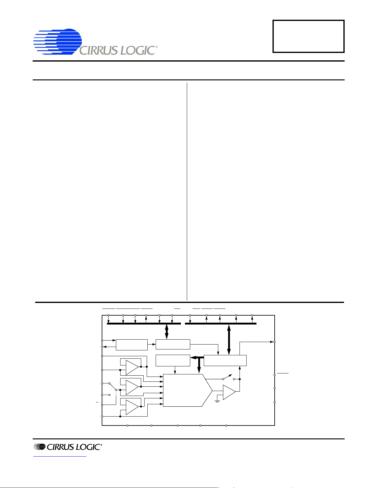
The CS5101A and CS5102A each consist of a 2-channel input multiplexer, DAC, conversion and calibration
microcontroller, clock generator, comparator, and serial
communications port. The inherent sampling architecture of the device eliminates the need for an external
track-and-hold amplifier.
The converters’ 16-bit data is output in serial form with
either binary or two’s complement coding. Three output
timing modes are available for easy interfacing to microcontrollers and shift registers. Unipolar and bipolar input
ranges are digitally selectable
ORDERING INFORMATION
See “Ordering Information” on page 38.
REFBUF
http://www.cirrus.com
HOLDSLEEPRST CODEBP/UP
12 28 2 5 16 17 8 9 11 15
XOUT
VREF
AIN1
AIN2
CH1/2
3
4
21
20
19
24
13
22
Clock
Generator
-
+
-
+
-
+
25 23
CLKIN
AGND
STBY
Calibration
Copyright © Cirrus Logic, Inc. 2005
CRS/FIN
Control
SRAM
16-Bit Charge
Redistribution
DAC
DGND VD- VD+VA-VA+
(All Rights Reserved)
TRK1
10
SSH/SDL
TRK2
Microcontroller
-
+
Comparator
716
SDATA
14
26
27
18
SCLK
TEST
SCKMOD
OUTMOD
AUG ‘05
DS45F5
Page 2

CS5101A CS5102A
TABLE OF CONTENTS
1. CHARACTERISTICS & SPECIFICATIONS ............................................................................. 4
ANALOG CHARACTERISTICS, CS5101A............................................................................... 4
SWITCHING CHARACTERISTICS, CS5101A.........................................................................6
ANALOG CHARACTERISTICS, CS5102A............................................................................... 7
SWITCHING CHARACTERISTICS, CS5102A.........................................................................9
SWITCHING CHARACTERISTICS, ALL DEVICES ............................................................... 11
DIGITAL CHARACTERISTICS, ALL DEVICES......................................................................13
RECOMMENDED OPERATING CONDITIONS .....................................................................13
ABSOLUTE MAXIMUM RATINGS .........................................................................................14
2. OVERVIEW .............................................................................................................................15
3. THEORY OF OPERATION .....................................................................................................15
3.1 Calibration . ... .... ... ... ... .... ... ....................................... ... ... ... ................................................ 16
4. FUNCTIONAL DESCRIPTION ............................................................................................... 17
4.1 Initiating Conversions ....................................................................................................... 17
4.2 Tracking the Input ............................ ... ... .... ... ....................................... ... ... ... ...................17
4.3 Master Clock .......... ... .... ... ....................................... ... ... ... ....................................... ......... 18
4.4 Asynchronous Sampling Considerations .........................................................................18
4.5 Analog Input Range/Coding Format ................................................................. ... ... ... ... ... 19
4.6 Output Mode Control ........................................................................................................19
4.6.1 Pipelined Data Transmission .............................................................................. 19
4.6.2 Register Burst Transmission (RBT) ....................................................................20
4.6.3 Synchronous Self-clocking (SSC) .................................... ... .... ... ... ......................20
4.6.4 Free Run (FRN) ..................................................................................................20
5. SYSTEM DESIGN USING THE CS5101A & CS5102A ......................................................... 22
5.1 System Initialization ...................... ... ... ... .... ... ....................................... ... ... ... .... ...............22
5.2 Single-channel Operation ................................................................ .... ... ......................... 23
6. ANALOG CIRCUIT CONNECTIONS ...................................................................................... 23
6.1 Reference Considerations ...............................................................................................23
6.2 Analog Input Connection ................................. ....................................... ... ... .... ... ............24
6.3 Sleep Mode Operation .....................................................................................................24
6.4 Grounding & Power Supply Decoupling ............................... ... ... ... ... .... ... ......................... 25
7. CS5101A & CS5102A PERFORMANCE ............................................................................... 26
7.1 Differential Nonlinearity . ... ... ... ....................................... ... .... ... ... ......................................26
7.2 FFT Tests and Windowing ...............................................................................................28
7.3 Sampling Distortion ... .... ... ... ....................................... ... ... .... ...................................... ...... 30
7.4 Noise ...... ....................................... ... ... ... ....................................... ... .... ... .........................31
7.5 Aperture Jitter .................................................................. .... ... ......................................... 31
7.6 Power Supply Rejection ... ... ....................................... ... ... .... ... ...................................... ... 32
8. PIN DESCRIPTIONS .............................................................................................................. 33
8.1 Power Supply Connections . ... ....................................... ... .... ... ... ...................................... 33
8.2 Oscillator ...... .... ... ... ... ....................................... ... .... ... ... ....................................... ............ 34
8.3 Digital Inputs .......................... .... ... ....................................... ... ... ... ... ................................34
8.4 Analog Inputs ............ .... ... ... ... ....................................... ... .... ... ... ...................................... 35
8.5 Digital Outputs ................................................................. .... ... ......................................... 35
8.6 Analog Outputs .......................... ... ... ... ... ....................................... ... .... ... .........................35
8.7 Miscellaneous ........................ .... ...................................... .... ... ... ...................................... 35
9. PARAMETER DEFINITIONS .................................................................................................. 36
10. PACKAGE DIMENSIONS ..................................................................................................... 37
11. ORDERING INFORMATION ................................................................................................ 38
12. ENVIRONMENTAL, MANUFACTURING, & HANDLING INFORMATION ........... ...............38
13. REVISIONS ..........................................................................................................................39
2 DS45F5
Page 3

CS5101A CS5102A
LIST OF FIGURES
Figure 1. Reset, Calibration, and Control Timing .......................................................................... 10
Figure 2. Serial Communication Timing........................................................................................12
Figure 3. Coarse Charge Input Buffers & Charge Redistribution DAC . ... ... ... .... ... ... ......................15
Figure 4. Coarse/Fine Charge Control .......................................................................................... 18
Figure 5. Pipelined Data Transmission (PDT) Mode Timing......................................................... 20
Figure 6. Register Burst Transmission (RBT) Mode Timing..........................................................21
Figure 7. Synchronous Self-clocking (SSC) Mode Timing ............................................................ 21
Figure 8. Free Run (FRN) Mode Timing........................................................................................21
Figure 9. CS5101A/CS5102A System Connection Diagram... ... ... .... ... ... ... ... ................................ 22
Figure 10. Power-up Reset Circuit ... ... .... ...................................... .... ... ... ... ................................... 23
Figure 11. Reference Connections................................................................................................24
Figure 12. Charge Settling Time ...................................................................................................24
Figure 13. CS5101A DNL Plot - Ambient Temperature at 25 °C .................................................. 27
Figure 14. CS5101A DNL Plot - Ambient Temperature at 138 °C ................................................ 27
Figure 15. CS5102A DNL Plot - Ambient Temperature at 25 °C .................................................. 27
Figure 16. CS5102A DNL Plot - Ambient Temperature at 138 °C ................................................ 27
Figure 17. CS5101A DNL Error Distribution..................................................................................28
Figure 18. CS5102A DNL Error Distribution..................................................................................28
Figure 19. CS5101A FFT (SSC Mode, 1-Channel)....................................................................... 29
Figure 20. CS5101A FFT (SSC Mode, 1-Channel)....................................................................... 29
Figure 21. CS5102A FFT (SSC Mode, 1-Channel)....................................................................... 29
Figure 22. CS5102A FFT (SSC Mode, 1-Channle)....................................................................... 29
Figure 23. CS5101A Histogram Plot of 8192 Conversion Inputs .................................................. 31
Figure 24. CS5102A Histogram Plot of 8192 Conversion Inputs .................................................. 31
Figure 25. Power Supply Rejection...............................................................................................32
Figure 26. CS5101A & CS5102A 28-pin PLCC Pinout ................................................................. 33
Figure 27. 28-Pin PLCC Mechanical Drawing............................................................................... 37
LIST OF TABLES
Table 1. Output Coding ................................................................................................................. 19
Table 2. Output Mode Control....................................................................................................... 19
DS45F5 3
Page 4
CS5101A CS5102A
1. CHARACTERISTICS & SPECIFICATIONS
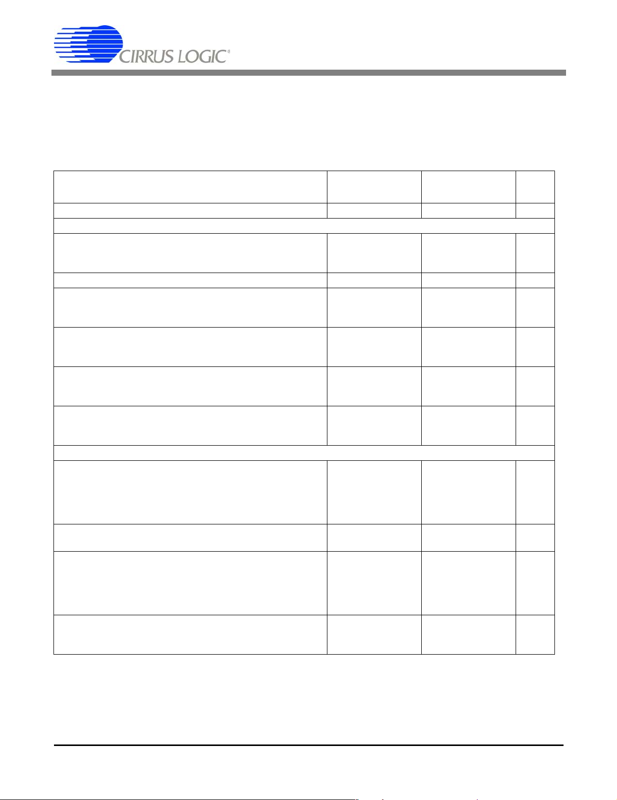
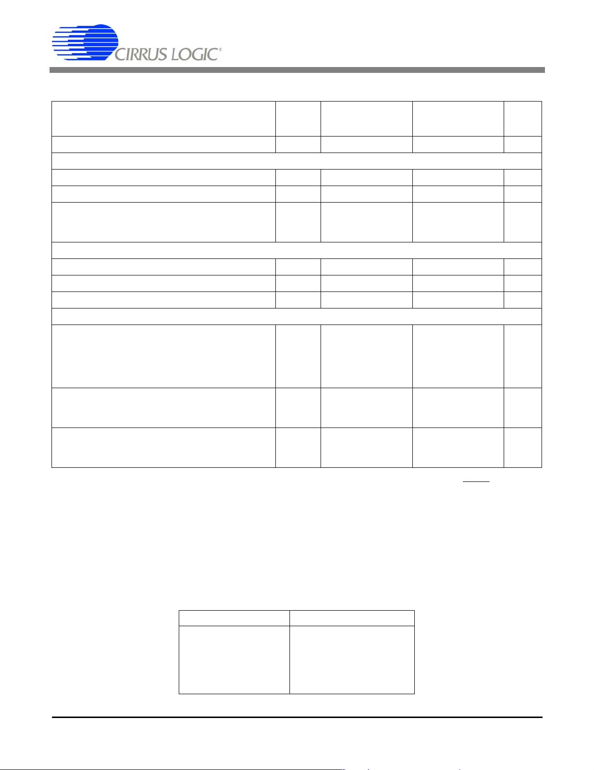
ANALOG CHARACTERISTICS, CS5101A
(TA = TMIN to TMAX; VA+, VD+ = 5V; VA-, VD- = -5V; VREF = 4.5V; Full-scale Input sine wave, 1 kHz; CLKIN = 8 MHz; fs =
100 kSps; Bipolar Mode; FRN Mode; AIN1 and AIN2 tied together, each channel tested separately; Analog Source Impedance
= 50 Ω with 1000 pF to AGND unless otherwise specified)
CS5101A-J CS5101A-B
Parameter*
Specified Temperature Range 0 to +70 -40 to +85 ºC
Accuracy
±¼
±1
±1
±1
±2
±2
±1
±2
±2
±2
±1
±1
±1
100
102
88
91
90
92
30
32
35
70
0.003
0.002
±4
±3
±5
±4
±5
±3
±4
±3
Differential Input Range -J (Note 1)
-B
Drift (Note 2)
Differential Linearity (Note 3)
Full-scale Error -J (Note 1)
-B
Drift (Note 2)
Unipolar Offset -J (Note 1)
-B
Drift (Note 2)
Bipolar Offset -J (Note 1)
-B
Drift (Note 2)
Bipolar Negative Full-scale Error -J (Note 1)
-B
Drift (Note 2)
Dynamic Performance (Bipolar Mode)
Peak Harmonic or Spurious Noise (Note 1)
1-kHz Input -J
-B
12-kHz Input -J
-B
Total Harmonic Distortion -J
-B
Signal-to-Noise Ratio (Note 1)
0 dB Input -J
-B
-60 dB Input -J
-B
Noise (Note 4)
Unipolar Mode
Bipolar Mode
0.002
-
0.001
-
-
-
-
-
-
-
-
-
-
-
-
-
-
96
98
85
85
--0.002
0.001--
87
90
-
-
-
-
±¼
±1
±1
±1
±2
±2
±1
±2
±2
±1
±1
±1
±1
100
102
88
91
90
92
30
32
35
70
0.003
0.002
-
±4
±3
-
±5
±4
-
±5
±3
-
±4
±3
-
-
-
-
-
-
-
-
-
-
-
0.002
-
0.001
-
-
16 --16--Bits
-
-
-
-
-
-
-
-
-
-
-
-
96
98
85
85
--0.002
0.001--
87
90
-
-
-
-
UnitMin Typ Max Min Typ Max
%FS
%FS
∆LSB
-
LSB
LSB
∆LSB
LSB
LSB
∆LSB
LSB
LSB
∆LSB
LSB
LSB
∆LSB
-
-
-
-
-
-
-
-
-
-
-
dB
dB
dB
dB
%
%
dB
dB
dB
dB
µV
rms
µVrms
Notes: 1. Applies after calibration at any temperature within the specified temperature range.
2. Total drift over specified temperature range after calibration at power-up, at 25
3. Minimum resolution for which no missing codes is guaranteed over the specified temperature range.
4. Wideband noise aliased into the baseband, referred to the input.
* Refer to Parameter Definitions (immediately following the pin descriptions at the end of this data sheet.
4 DS45F5
º C.
Page 5
CS5101A CS5102A
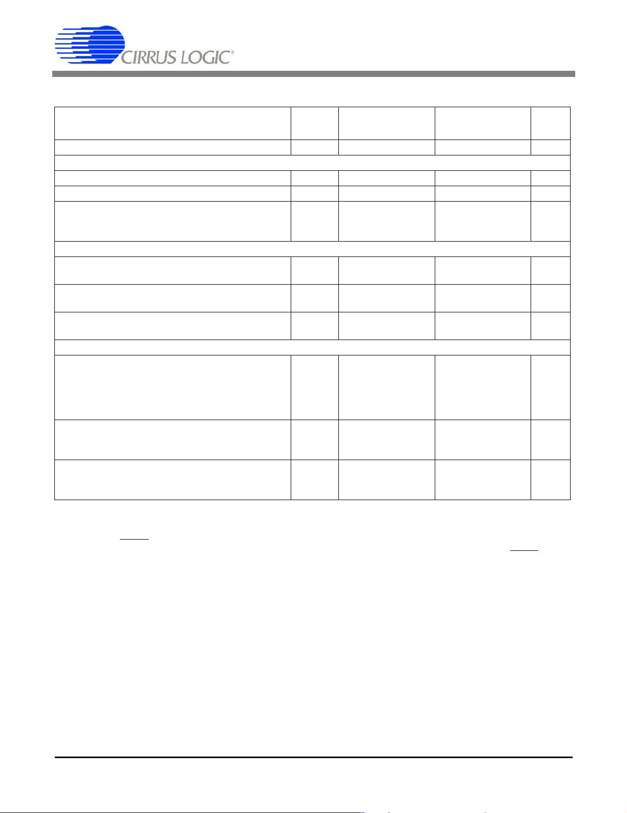
ANALOG CHARACTERISTICS, CS5101A (Continued)
CS5101A-J CS5101A-B
Parameter* Symbol
Specified Te mperature Range - 0 to +70 -40 to +85 ºC
Analog Input
Aperture Time - - 25 - - 25 - ns
Aperture Jitter -
- 100 - - 100 - ps
Input Capacitance (Note 5)
Unipolar Mode
Bipolar Mode
-
-
--320
200
425
265
-
320
-
200
425
265
Conversion and Throughput
Conversion Time (Note 6)
t
c
- - 8.12 - - 8.12 µs
Acquisition Time (Note 7)
t
a
- - 1.88 - - 1.88 µs
Throughput (Note 8)
f
tp
100 - - 100 - - kSps
Power Supplies
Power Supply Current (Note 9)
Positive Analog
Negative Analog
(SLEEP High) Positive Digital
Negative Digital
21
I
+
A
I
-
A
I
+
D
I
-
D
21
-
-21
-
11
-
-11
-
28
-28
15
-15
-
-21
11
-
-11
-
28
-28
15
-15
Power Consumption (Note 9, Note 10)
(SLEEP High)
(SLEEP Low)
P
do
P
ds
--3201430
-
-
3201430-mW
-
Power Supply Rejection (Note 11)
Positive Supplies
Negative Supplies
PSR
PSR
-
84
-
84
-
-
-
84
-
84
UnitMin Typ Max Min Typ Max
mA
mA
mA
mA
mW
-
-
pF
pF
dB
dB
Notes:
5. Applies only in the track mode. When converting or calibrating, inpu t capacitance will not exceed 30 pF.
6. Conversion time scales directly to the master clock speed. The times shown are for synchronous, internal loopback
(FRN) mode) with 8.0 MHz CLKIN. In PDT, RBT, and SSC modes, asynchronous delay between the falling edge
HOLD and the start of conversion may add to the apparent conversion time. This delay will not exceed 1.5
of
master clock cycles + 10 ns. In PDT, RBT, and SSC modes, CLKIN can be increased as long as the
rate is 100 kHz max.
7. The CS5101A requires 6 clock cycles of coarse charge, followed by a minimum of 1.125 µs of fine charge. FRN
mode allows 9 cycles for fine charge which provides for the minimum 1.125 µs with an 8MHz clock, however; in
PDT, RBT, or SSC modes and at clock frequencies of 8 MHz or less, fine charge may be less than 9 clock cycles.
This reflects the typical specification (6 clock cycles + 1.125 µs).
8. Throughput is the sum of the acquisition and conversion times. It will vary in accordance with conditions affecting
acquisition and conversion times, as described above.
9. All outputs unloaded. All inputs at VD+ or DGND.
10. Power consumption in the sleep mode applies with no master clock applied (CLKIN held high or low).
11. With 300 mV p-p, 1-kHz ripple applied to each supply separately in the bipolar mode. Rejection improves by 6 dB
in the unipolar mode to 90 dB. Figure 25 shows a plot of typical power supply rejection versus frequency.
HOLD sample
DS45F5 5
Page 6

CS5101A CS5102A
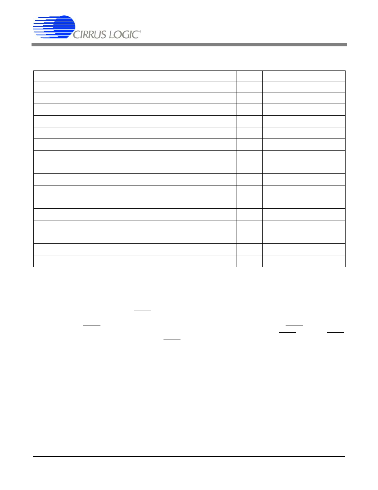
SWITCHING CHARACTERISTICS, CS5101A
(TA = TMIN to TMAX; VA+, VD+ = 5V ±10%; VA-, VD- = -5V ±10%; Inputs: Logic 0 = 0V, Logic 1 = VD+; CL = 50 pF).
Parameter Symbol Min Typ Max Unit
CLKIN Period
t
clk
CLKIN Low Time t
CLKIN High Time t
clkl
clkh
Crystal Frequency (Note 12)
f
xtal
SLEEP Rising to Oscillator Stable (Note 13) - - 2 - ms
108 - 10,000 ns
37.5 - - ns
37.5 - - ns
2.0 - 9.216 MHz
RST Pulse Width t
RST to STBY falling t
RST Rising to STBY Rising t
CH1/2 Edge to TRK1, TRK2 Rising (Note 14) t
CH1/2 Edge to TRK1, TRK2 Falling (Note 14) t
HOLD to SSH Falling (Note 15) t
HOLD to TRK1, TRK2 Falling (Note 15) t
HOLD to TRK1, TRK2, SSH Rising (Note 15) t
HOLD Pulse Width (Note 16) t
HOLD to CH1/2 Edge (Note 15) t
HOLD Falling to CLKIN Falling (Note 16) t
rst
drrs
cal
drsh1
dfsh4
dfsh2
dfsh1
drsh
hold
dhlri
hcf
150 - - ns
-100 -ns
- 1 1,528,160 - t
clk
-80 -ns
--68t
+260 ns
clk
-60 -ns
66t
clk
-68t
+260 ns
clk
-120 -ns
1t
+20 - 63t
clk
15 - 64t
95 - 1t
clk
clk
+10 ns
clk
ns
ns
Notes: 12. External loading capacitors are required to allow the crystal to oscillate. Maximum crystal frequency is 8.0 MHz in
FRN mode (100 kSps).
13. With an 8.0 MHz crystal, two 10 pF loading capacitors and a 10 MΩ parallel resistor (see Figure 9).
14. These timings are for FRN mode.
15. SSH only works correctly if
HOLD rises to 64t
16. When
HOLD goes low, the analog sample is captured immediately. To start conversion, HOLD must be latched
by a falling edge of CLLKIN. Conversion will begin on the next rising edge of CLKIN after
is operated synchronous to CLKIN, the
if CLKIN falls 95 ns after HOLD falls. This ensures that the HOLD pulse will meet the minimum specification for t
clk
HOLD falling edge is within +15 to +30 ns of CH1/2 edge or if CH1/2 edge occurs after
after HOLD has fallen. These timings are for PDT and RBT modes.
HOLD is latched. If HOLD
HOLD pulse width may be as narrow as 150 ns for all CLKIN frequencies
hcf
.
6 DS45F5
Page 7
CS5101A CS5102A
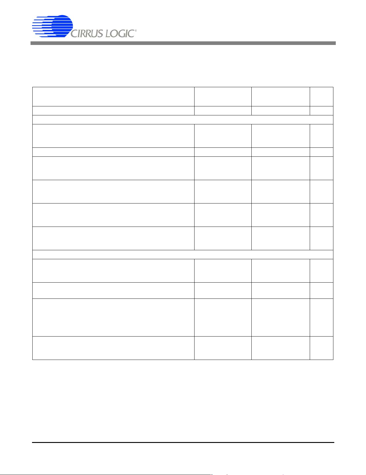
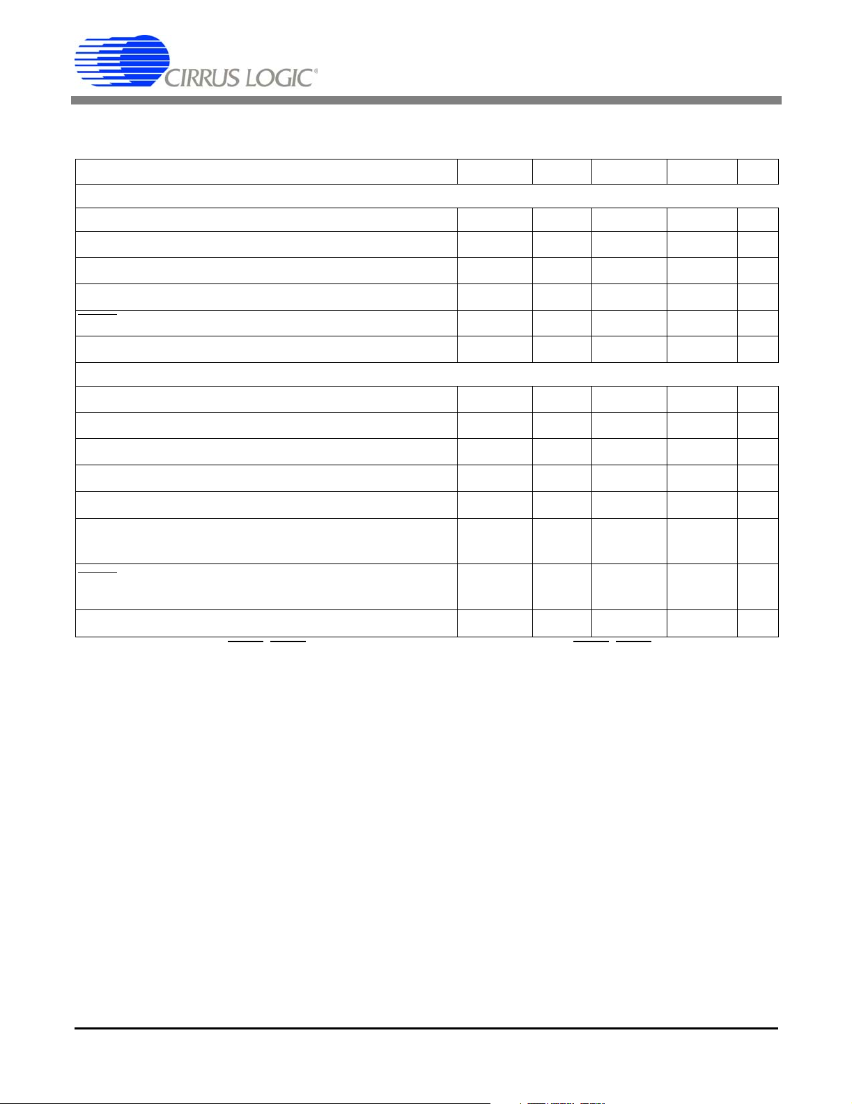
ANALOG CHARACTERISTICS, CS5102A
(TA = TMIN to TMAX; VA+, VD+ = 5V; VA-, VD- = -5V; VREF = 4.5V; Full-scale Input Sine Wave, 200 Hz; CLKIN = 1.6 MHz;
fs = 20 kSps; Bipolar Mode; FRN Mode; AIN1 and AIN2 tied together, each channel tested separately; Analog Source
Impedance = 50 Ω with 1000 pF to AGND unless otherwise specified)
CS5102A-J CS5102A-B
Parameter*
Specified Te mperature Range 0 to +70 -40 to +85 ºC
Accuracy
±¼
±2
±2
±1
±1
±1
±1
±1
±1
±2
±2
±2
±2
102
90
92
30
32
35
70
0.003
0.0015
-
±4
±3
-
±4
±3
-
±4
±3
-
±4
±3
-
-
-
-
-
-
-
-
-
Differential Input Range -J (Note 1)
-B
Drift (Note 2)
Differential Linearity (Note 3)
Full-scale Error -J (Note 1)
-B
Drift (Note 2)
Unipolar Offset -J (Note 1)
-B
Drift (Note 2)
Bipolar Offset -J (Note 1)
-B
Drift (Note 2)
Bipolar Negative Full-scale Error -J (Note 1)
-B
Drift (Note 2)
Dynamic Performance (Bipolar Mode)
Peak Harmonic or Spurious Noise (Note 1)
-J
-B
Total Harmonic Distortion -J
-B
Signal-to-Noise Ratio (Note 1)
0 dB Input -J
-B
-60 dB Input -J
-B
Noise (Note 4)
Unipolar Mode
Bipolar Mode
0.002
-
0.001
-
-
-
-
-
-
-
-
-
-
-
-
-
-
9698100
--0.002
0.001--
87
90
-
-
-
-
±¼
±2
±2
±1
±1
±1
±1
±1
±1
±1
±2
±2
±1
102
90
92
30
32
35
70
0.003
0.0015
-
±4
±3
-
±4
±3
-
±4
±3
-
±4
±3
-
-
-
-
-
-
-
-
-
0.002
-
0.001
-
-
16 --16--Bits
-
-
-
-
-
-
-
-
-
-
-
-
9698100
--0.002
0.001--
87
90
-
-
-
-
UnitMin Typ Max Min Typ Max
%FS
%FS
∆LSB
LSB
LSB
∆LSB
LSB
LSB
∆LSB
LSB
LSB
∆LSB
LSB
LSB
∆LSB
dB
dB
%
%
dB
dB
dB
dB
µV
rms
µVrms
* Refer to Parameter Definitions (immediately following the pin descriptions at the end of this data sheet.
DS45F5 7
Page 8
ANALOG CHARACTERISTICS, CS5102A (Continued)
CS5102A-J CS5102-B
CS5101A CS5102A
Parameter* Symbol
UnitMin Typ Max Min Typ Max
Specified Te mperature Range - 0 to +70 -40 to +85 ºC
Analog Input
Aperture Time - - 30 - - 30 - ns
Aperture Jitter -
- 100 - - 100 - ps
Input Capacitance (Note 5)
Unipolar Mode
Bipolar Mode
-
-
--320
200
425
265
--320
200
425
265
pF
pF
Conversion and Throughput
Conversion Time (Note 17) t
Acquisition Time (Note 18) t
Throughput (Note 19) f
c
a
tp
- - 40.625 - - 40.625 µs
- - 9.375 - - 9.375 µs
20 - - 20 - - kSps
Power Supplies
Power Supply Current (Note 20)
Positive Analog
Negative Analog
(SLEEP High) Positive Digital
Negative Digital
2.4
I
+
A
I
-
A
I
+
D
I
-
D
2.4
-
-2.4
-
2.5
-
-1.5
-
3.5
-3.5
3.5
-2.5
-
-2.4
-
2.5
-
-1.5
-
3.5
-3.5
3.5
-2.5
mA
mA
mA
mA
Power Consumption (Note 10, Note 20)
(SLEEP High)
(SLEEP Low)
P
do
P
ds
-
44
-
65
1
-
-
44
-
1
65
mW
-
mW
Power Supply Rejection (Note 21)
Positive Supplies
Negative Supplies
PSR
PSR
-
84
-
84
-
-
-
84
-
84
-
-
dB
dB
Notes:
17. Conversion time scales directly to the master clock speed. The times shown are for synchronous, internal loopback
(FRN) mode. In PDT, RBT, and SSC modes, asynchronous delay between the falling edge of
of conversion may add to the apparent conversion time. This delay will not exceed 1 master clock cycle + 140 ns.
18. The CS5102A requires 6 clock cycles of coarse charge, followed by a minimum of 5.625 µs of fine charge. FRN
mode allows 9 cycles for fine charge which provides for the minimum 5.625 µs with a 1.6 MHz clock, however; in
PDT, RBT, or SSC modes and at clock frequencies of less than 1.6 MHz, fine charge may be less than 9 clock
cycles.
19. Throughput is the sum of the acquisition and conversion times. It will vary in accordance with conditions affecting
acquisition and conversion times, as described above.
20. All outputs unloaded. All inputs at VD+ or DGND. See table below for power dissipation versus clock frequency.
21. With 300 mV p-p, 1-kHz ripple applied to each supply separately in the bipolar mode. Rejection improves by 6 dB
in the unipolar mode to 90 dB. Figure 25 shows a plot of typical power supply rejection versus frequency.
HOLD and the start
Typical Power (mW) CLKIN (MHz)
34 0.8
37 1.0
39 1.2
41 1.4
44 1.6
8 DS45F5
Page 9
CS5101A CS5102A
SWITCHING CHARACTERISTICS, CS5102A
(TA = TMIN to TMAX; VA+, VD+ = 5V ±10%; VA-, VD- = -5V ±10%; Inputs: Logic 0 = 0V, Logic 1 = VD+; CL = 50 pF).
Parameter Symbol Min Typ Max Unit
CLKIN Period (Note 22) t
CLKIN Low Time t
CLKIN High Time t
Crystal Frequency (Note 22, Note 23) f
clk
clkl
clkh
xtal
SLEEP Rising to Oscillator Stable (Note 24) - - 20 - ms
0.5 - 10 µs
200 - - ns
200 - - ns
0.9 1.6 2.0 MHz
RST Pulse Width t
RST to STBY falling t
RST Rising to STBY Rising t
CH1/2 Edge to TRK1, TRK2 Rising (Note 25) t
CH1/2 Edge to TRK1, TRK2 Falling (Note 25) t
HOLD to SSH Falling (Note 26) t
HOLD to TRK1, TRK2 Falling (Note 26) t
HOLD to TRK1, TRK2, SSH Rising (Note 26) t
HOLD Pulse Width (Note 27) t
HOLD to CH1/2 Edge (Note 26) t
HOLD Falling to CLKIN Falling (Note 27) t
Notes: 22. Minimum CLKIN period is 0.625 ms in FRN mode (20 kSps).
23. External loading capacitors are required to allow the crystal to oscillate. Maximum crystal frequency is 1.6 MHz in
FRN mode (20 kSps).
24. With a 2.0 MHz crystal, two 33 pF loading capacitors and a 10 MΩ parallel resistor (see Figure 9).
25. These timings are for FRN mode.
26. SSH only works correctly if
HOLD rises to 64t
27. When
HOLD goes low, the analog sample is captured immediately. To start conversion, HOLD must be latched
by a falling edge of CLLKIN. Conversion will begin on the next rising edge of CLKIN after
is operated synchronous to CLKIN, the HOLD pulse width may be as narrow as 150 ns for all CLKIN frequencies
if CLKIN falls 55 ns after
clk
HOLD falling edge is within +15 to +30 ns of CH1/2 edge or if CH1/2 edge occurs after
after HOLD has fallen. These timings are for PDT and RBT modes.
HOLD falls. This ensures that the HOLD pulse will meet the minimum specification for t
rst
drrs
cal
drsh1
dfsh4
dfsh2
dfsh1
drsh
hold
dhlri
hcf
150 - - ns
-100 -ns
- 2,882,040 - t
clk
-80 -ns
--68t
+260 ns
clk
-60 -ns
66t
clk
-68t
+260 ns
clk
-120 -ns
1t
+20 - 63t
clk
15 - 64t
55 - 1t
clk
clk
+10 ns
clk
ns
ns
HOLD is latched. If HOLD
hcf
.
DS45F5 9
Page 10
t
rst
RST
STBY
t
drrs
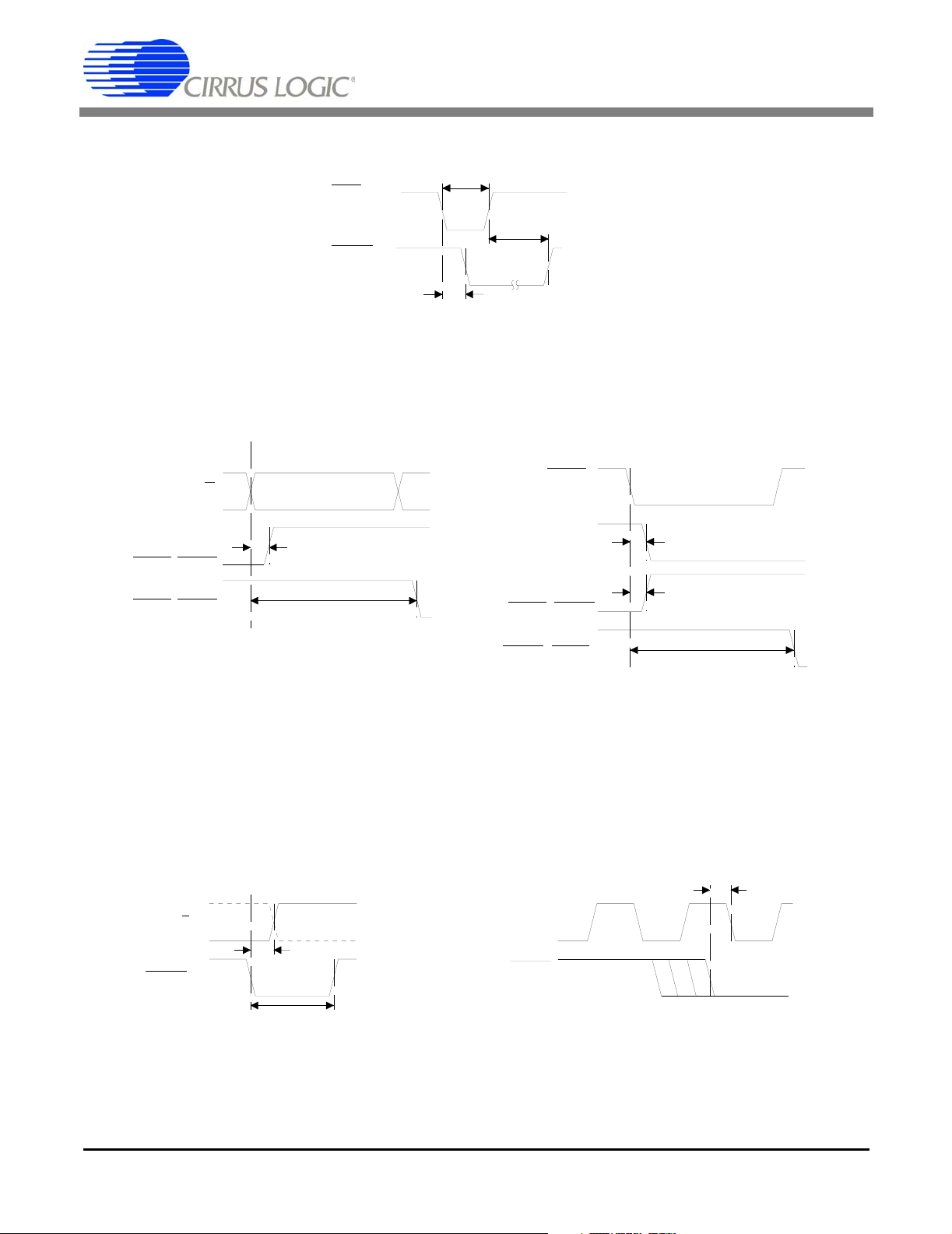
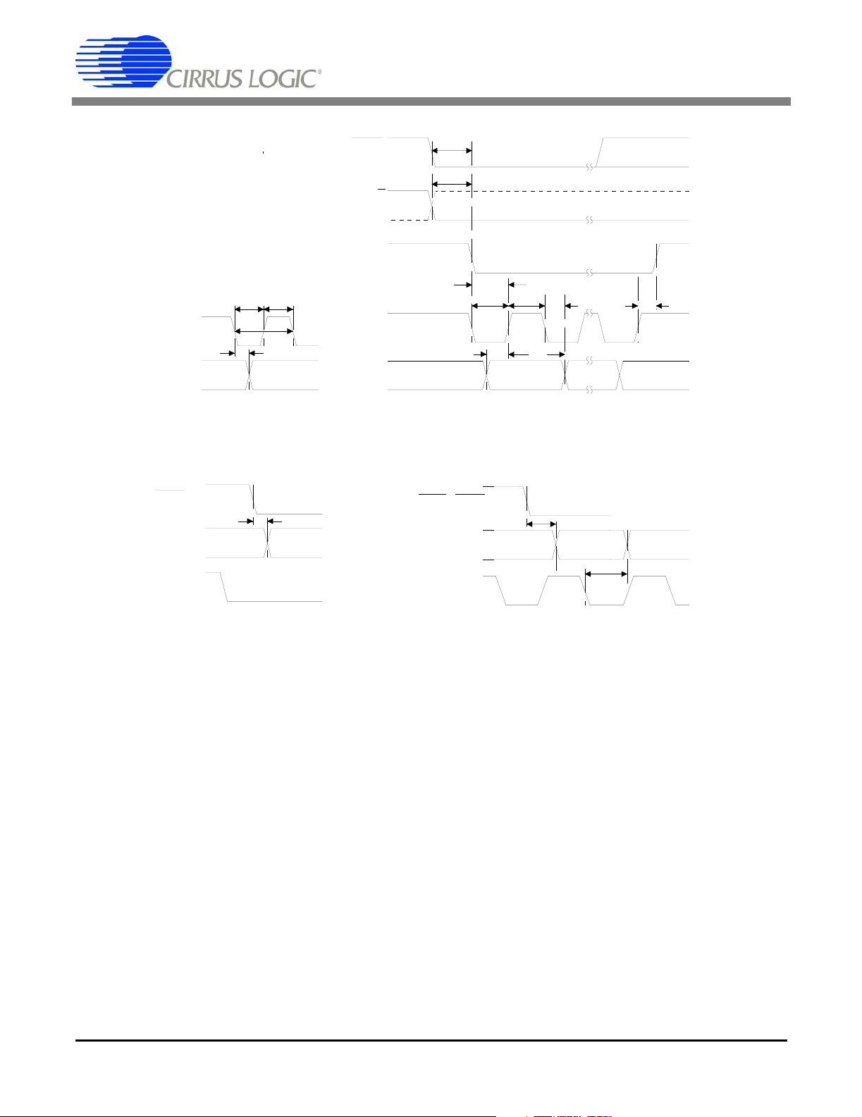
Reset and Calibration Timing
t
CS5101A CS5102A
cal
CH1/2
TRK1,TRK2
TRK1,TRK2
CH1/2
HOLD
HOLD
SSH/SDL
t
drsh1
t
dfsh4
SSH,TRK1,TRK2
TRK1,TRK2
a. FRN Mode b. PDT, RBT Mode
t
dfsh2
t
drsh
t
dfsh1
Control Output Timing
t
dhlri
CLKIN
HOLD
t
hcf
t
hold
Channel Selection Timing Start Conversion Timing
Figure 1. Reset, Calibration, and Control Timing
10 DS45F5
Page 11
CS5101A CS5102A
SWITCHING CHARACTERISTICS, ALL DEVICES
(TA = TMIN to TMAX; VA+, VD+ = 5V ±10%; VA-, VD- = -5V ±10%; Inputs: Logic 0 = 0V, Logic 1 = VD+; CL = 50 pF).
Parameter Symbol Min Typ Max Unit
PDT & RBT Modes
SCLK Input Pulse Period t
SCLK Input Pulse Width Low t
SCLK Input Pulse Width High t
SCLK Input Falling to SDATA Valid t
HOLD
Falling to SDATA Valid PDT Mode t
TRK1, TRK2 Falling to SDATA Valid (Note 28) t
FRN & SSC Modes
sclk
sclkl
sclkh
dss
dhs
dts
200 - - ns
50 - - ns
50 - - ns
-100150ns
-140230ns
-65125ns
SCLK Output Pulse Width Low t
SCLK Output Pulse Width High t
SDATA Valid Before Rising SCLK t
SDATA Valid After RIsing SCLK t
st
SDL Falling to 1
Rising SCLK
Last Rising SCLK to SDL Rising CS5101A
CS5102A
HOLD
Falling to 1st Falling SCLK CS5101A
CS5102A
CH1/2 Edge to 1
st
Falling SCLK
slkl
slkh
t
rsclk
t
rsdl
t
rsdl
t
hfs
t
hfs
t
dhlri
ss
sh
-2t
-2t
2t
-100 - - ns
clk
2t
-100 - - ns
clk
66t
clk
-
-
6t
clk
6t
clk
-7t
2t
2t
2t
clk
clk
clk
clk
clk
-
-
clk
-t
-t
68t
+260 ns
clk
2t
+165
clk
+200
2t
clk
8t
+165
clk
+200
8t
clk
64t
clk
ns
ns
t
clk
clk
clk
Notes: 28. Only valid for TRK1, TRK2 falling when SCLK is low. If SCLK is high when TRK1, TRK2 falls, then SDATA is
valid t
time after the next falling SCLK.
dss
DS45F5 11
Page 12
CS5101A CS5102A
t
HOLD
CH1/2
SSH/SDL
t
sclkltsclkh
SCLK
t
SCLK
SDATA
t
dss
sclk
SDATA
a. SCLK Input (PDT & RBT Modes) b. SCLK Output (FRN & SSC Modes)
Serial Data Timing
hfs
t
chfs
t
rsclk
t
t
t
ss
slkl
slkh
MSB
t
sh
t
dss
LSB
t
rsdl
HOLD
SDATA
SCLK
t
dhs
MSB
TRK1, TRK2
SDATA
SCLK
t
dts
MSB
t
dss
MSB-1
a. Pipelined Data Transmission (PDT) b. Register Burst Transmission (RBT)
Data Transmission Timing
Figure 2. Serial Communication Timing
12 DS45F5
Page 13

DIGITAL CHARACTERISTICS, ALL DEVICES
(TA = TMIN to TMAX; VA+, VD+ = 5V ±10%; VA-, VD- = -5V ±10%
Parameter Symbol Min Typ Max Unit
Calibration Memory Retention (Note 29)
Power Supply Voltage VA+ and VD+
High-level Input Voltage V
Low-level Input Voltage V
High-level Output Voltage (Note 30) V
Low-level Output Voltage (except XOUT) I
= 1.6 mA V
out
Input Leakage Current I
Digital Output Pin Capacitance C
29. VA- and VD- can be any value from 0 to +5V for memory retention. Neither VA- nor VD- should be allowed to go
positive. AIN1, AIN2, or VREF must not be greater than VA+ or VD+. This parameter is guaranteed by
characterization.
30. I
= -100 µA. This specification guarantees TTL compatibility (VOH = 2.4V @ I
OUT
RECOMMENDED OPERATING CONDITIONS
(AGND, DGND = 0V, see Note 31)
CS5101A CS5102A
V
MR
IH
IL
OH
OL
in
out
2.0 - - V
2.0 - - V
--0.8V
(VD+) -1.0 - - V
--0.4V
--10µA
-9-pF
= -40 µA).
OUT
Parameter Symbol Min Typ Max Unit
DC Power Supplies:
Positive Digital
Negative Digital
Positive Analog
Negative Analog
VD+
VDVA+
VA-
4.5
-4.5
4.5
-4.5
5.0
-5.0
5.0
-5.0
VA+
-5.5
5.5
-5.5
Analog Reference Voltage VREF 2.5 4.5 (VA+)-0.5 V
DC Power Supplies: (Note 32)
Unipolar
Bipolar
31. All voltages with respect to ground.
32. The CS5101A and CS5102A can accept input voltages up to the analog supplies (VA+ and VA-). They will produce
an output of all 1s for input above VREF and all 0s for inputs below AGND in unipolar mode, and -VREF in bipolar
mode, with binary coding (CODE = low).
V
AIN
V
AIN
AGND
-VREF
-
-
VREF
VREF
V
V
V
V
V
V
DS45F5 13
Page 14

ABSOLUTE MAXIMUM RATINGS
(AGND, DGND = 0V, all voltages with respect to ground.)
Parameter Symbol Min Typ Max Unit
DC Power Supplies: (Note 33)
Positive Digital
Negative Digital
Positive Analog
Negative Analog
Input Current, Any Pin Except Supplies (Note 34) I
Analog Input Vo ltage (AIN and VREF pins) V
Digital Input Voltage V
Ambient Operating Temperature T
Storage Temperature T
Notes:
33. In addition, VD+ must not be greater than (VA+) + 0.3 V.
34. Transient currents of up to 100 mA will not cause SCR latch-up
WARNING: Operation beyond these limits may result in permanent damage to the device.
VD+
VD-
VA+
VA-
IN
INA
IND
A
stg
CS5101A CS5102A
-0.3
0.3
-0.3
0.3
-
-
-
6.0
-6.0
6.0
-6.0
--±10mA
(VA-) - 0.3 - (VA+) + 0.3 V
-0.3 - (VA+) + 0.3 V
-55 - 125 °C
-65 - 150 °C
V
V
V
V
14 DS45F5
Page 15

2. OVERVIEW
CS5101A CS5102A
The CS5101A and CS5102A are 2-channel, 16-bit
A/D converters. The devices include an inherent
sample/hold and an on-chip analog switch for 2channel operation. Both channels can thus be
sampled and converted at rates up to 50 kSps
each (CS5101A) or 10 kSps each (CS5102A). Alternatively, each of the devices can be operated as
a single channel ADC operating at 100 kSps
(CS5101A) or 20 kSps (CS5102A).
Both the CS5101A and CS5102A can be configured to accept either unipolar or bipolar input ranges, and data is output serially in either binary or 2's
complement coding. The devices can be configured in 3 different output modes, as well as an internal, synchronous loopback mode. The
CS5101A and CS5102A provide coarse
charge/fine charge control, to allow accurate tracking of high-slew signals.
3. THEORY OF OPERATION
The CS5101A and CS5102A implement the successive approximation algorithm using a charge
redistribution architecture. Instead of the traditional
resistor network, the DAC is an array of binaryweighted capacitors. All capacitors in the array
share a common node at the comparator's input.
As shown in Figure 3, their other terminals are capable of being connected to AGND, VREF, or AIN
(1 or 2). When the device is not calibrating or converting, all capacitors are tied to AIN. Switch S1 is
closed and the charge on the array, tracks the input signal.
When the conversion command is issued, switch
S1 opens. This traps the charge on the comparator
side of the capacitor array and creates a floating
node at the comparator's input. The conversion algorithm operates on this fixed charge, and the signal at the analog input pin is ignored. In effect, the
entire DAC capacitor array serves as analog memory during conversion much like the hold capacitor
in a sample/hold amplifier.
The conversion consists of manipulating the free
plates of the capacitor array to VREF and AGND to
form a capacitive divider. Since the charge at the
floating node remains fixed, the voltage at that
point depends on the proportion of capacitance
tied to VREF versus AGND. The successive approximation algorithm is used to find the proportion
of capacitance, which when connected to the reference will drive the voltage at the floating node to
zero. That binary fraction of capacitance represents the converter's digital output.
AIN
Fine
+
-
VREF
+
-
AGND
+
-
DS45F5 15
Coarse
Fine
Coarse
Fine
Coarse
Figure 3. Coarse Charge Input Buffers & Charge Redistribution DAC
C
Bit 15 Bit 14 Bit 13 Bit 0
M S B LSB
C/2 C/32,768
C = C + C/2 + C/4 + C /8 + ... C/32 ,768
tot
C/4
C/32,768
Dummy
S1
-
+
Page 16

CS5101A CS5102A
3.1 Calibration
The ability of the CS5101A or the CS5102A to convert accurately to 16-bits clearly depends on the
accuracy of its comparator and DAC. Each device
utilizes an “auto-zeroing” scheme to null errors introduced by the comparator. All offsets are stored
on the capacitor array while in the track mode and
are effectively subtracted from the input signal
when a conversion is initiated. Auto-zeroing enhances power supply rejection at frequencies well
below the conversion rate.
To achieve 16-bit accuracy from the DAC, the
CS5101A and CS5102A use a novel self-calibra-
tion scheme. Each bit capacitor shown in Figure 3
actually consists of several capacitors in parallel
which can be manipulated to adjust the overall bit
weight. An on-chip microcontroller precisely adjusts each capacitor with a resolution of 18 bits.
The CS5101A and CS5102A should be reset upon
power-up, thus initiating a calibration cycle. The
device then stores its calibration coefficients in onchip SRAM. When the CS5101A and CS5102A are
in power-down mode (SLEEP
calibration coefficients in memory, and need not be
recalibrated when normal operation is resumed.
low), they retain the
16 DS45F5
Page 17

4. FUNCTIONAL DESCRIPTION
Monolithic design and inherent sampling architecture make the CS5101A and CS5102A extremely
easy to use.
4.1 Initiating Conversions
A falling transition on the HOLD pin places the input in the hold mode and initiates a conversion cycle. The charge is trapped on the capacitor array
the instant HOLD
plete conversion of the sample within 66 master
clock cycles, then automatically return to the track
mode. After allowing a short time for acquisition,
the device will be ready for another conversion.
In contrast to systems with separate track-andholds and A/D converters, a sampling clock can
simply be connected to the HOLD
cycle of this clock is not critical. The HOLD
latched internally by the master clock, so it need
only remain low for 1/f
than the minimum conversion time minus two master clocks or an additional conversion cycle will be
initiated with inadequate time for acquisition. In
Free Run mode, SCKMOD = OUTMOD = 0, the
device will convert at a rate of CLKIN/80, and the
input is ignored.
HOLD
As with any high-resolution A-to-D system, it is rec-
ommended that sampling is synchronized to the
master system clock in order to minimize the effects of clock feed through. However, the
CS5101A and CS5102A may be operated entirely
asynchronous to the master clock if necessary.
goes low. The device will com-
input. The duty
input is
+ 20 ns, but no longer
clk
4.2 Tracking the Input
Upon completing a conversion cycle the CS5101A
and CS5102A immediately return to the track
mode. The CH1/2
switch, and therefore directly determines which
channel will be tracked. Ideally, the CH1/2
should be switched during the conversion cycle,
thereby nullifying the input mux switching time, and
guaranteeing a stable input at the start of acquisition. If, however, the CH1/2
ing the acquisition phase, adequate coarse charge
and fine charge time must be allowed before initiating conversion.
When the CS5101A or the CS5102A enters tracking mode, it uses an internal input buffer amplifier
pin directly controls the input
pin
control is changed dur-
CS5101A CS5102A
to provide the bulk of the charge on the capacitor
array (coarse-charge), thereby reducing the current load on the external analog circuitry. Coarsecharge is internally initiated for 6 clock cycles at the
end of every conversion. The buffer amplifier is
then bypassed, and the capacitor array is directly
connected to the input. This is referred to as finecharge, during which the charge on the array is allowed to accurately settle to the input voltage (see
Figure 12).
With a full-scale input step, the coarse-charge input buffer of the CS5101A will charge the capacitor
array within 1% in 650 ns. The converter timing allows 6 clock cycles for coarse charge settling time.
When the CS5101A switches to fine-charge mode,
its slew rate is somewhat reduced. In fine-charge,
the CS5101A can slew at 2 V/µs in unipolar mode.
In bipolar mode, only half the capacitor array is
connected to the analog input, so the CS5101A
can slew at 4V/µs.
With a full-scale input step, the coarse-charge input buffer of the CS5102A will charge the capacitor
array within 1% in 3.75 µs. The converter timing allows 6 clock cycles for coarse charge settling time.
When in fine-charge mode, the CS5102A can slew
at 0.4 V/µs in unipolar mode; and at 0.8 V/µs in bipolar mode.
Acquisition of fast slewing signals can be hastened
if the voltage change occurs during or immediately
following the conversion cycle. For instance, in
multiple channel applications (using either the device's internal channel selector or an external
MUX), channel selection should occur while the
CS5101A or the CS5102A is converting. Multiplexer switching and settling time is thereby removed
from the overall throughput equation.
If the input signal changes drastically during the
acquisition period (such as changing the signal
source), the device should be in coarse-charge for
an adequate period following the change. The
CS5101A and CS5102A can be forced into coarsecharge by bringing CRS/FIN
plifier is engaged when CRS/FIN
be switched in any number of times during tracking. If CRS/FIN is held low, the CS5101A and
CS5102A will only coarse-charge for the first 6
clock cycles following a conversion, and will stay in
high. The buffer am-
is high, and may
DS45F5 17
Page 18

CS5101A CS5102A
fine-charge until HOLD goes low. To get an accurate sample using the CS5101A, at least 750 ns of
coarse-charge, followed by 1.125 µs of fine-charge
is required before initiating a conversion. If coarse
charge is not invoked, then up to 25 µs should be
allowed after a step change input for proper acquisition. To get an accurate sample using the
CS5102A, at least 3.75 µs of coarse-charge, fol-
CLKIN
Min: 750 ns*
CRS/FIN
Inte rn al
Status
TRK1 or
TRK2
HOLD
Conv.
* Applies to 5101A
** Applies to 5102A
Coarse Fine Chg. Coarse Fine Chg. Conv.
2 clk
Figure 4. Coarse/Fine Charge Control
3.75 µs**
Min: 1.125 µs*
6 clk
lowed by 5.625 µs of fine-charge is required before
initiating a conversion (see Figure 4). If coarse
charge is not invoked, then up to 125 µs should be
allowed after a step change input for proper acquisition. The CRS/FIN
pin must be low prior to HOLD
becoming active and be held low during conversion.
5.625 µs**
4.3 Master Clock
The CS5101A and CS5102A can operate either
from an externally-supplied master clock, or from
their own crystal oscillator (with a crystal). To enable the internal crystal oscillator, simply tie a crystal across the XOUT and CLKIN pins and add 2
capacitors and a resistor, as shown on the system
connection diagram in Figure 9.
Calibration and conversion times directly scale to
the master clock frequency. The CS5101A can operate with clock or crystal frequencies up to 9.216
MHz (8.0 MHz in FRN mode). This allows maximum throughput of up to 50 kSps per channel in
dual-channel operation, or 100 kSps in a singlechannel configuration. The CS5102A can operate
with clock or crystal frequencies up to 2.0 MHz (1.6
MHz in FRN mode). This allows maximum
throughput of up to 10 kSps per channel in dualchannel operation, or 20 kSps in a single channel
configuration. For 16-bit performance a 1.6 MHz
clock is recommended. This 1.6 MHz clock yields
a maximum throughput of 20 kSps in a singlechannel configuration.
4.4 Asynchronous Sampling
Considerations
When HOLD goes low, the analog sample is captured immediately. The HOLD
the next falling edge of CLKIN, and conversion
then starts on the subsequent rising edge. If HOLD
is asynchronous to CLKIN, then there will be a 1.5CLKIN-cycle uncertainty as to when conversion
starts. Considering the CS5101A with an 8 MHz
CLKIN, with a 100 kHz HOLD
CLKIN uncertainty will result in a 1.5-CLKIN-period
possible reduction in fine charge time for the next
conversion.
This reduced fine charge time will be less than the
minimum specification. If the CLKIN frequency is
increased slightly (for example, to 8.192 MHz) then
sufficient fine charge time will always occur. The
maximum frequency for CLKIN is specified at
9.216 MHz. It is recommended that for asynchronous operation at 100 kSps, CLKIN should be between 8.192 MHz and 9.216 MHz.
signal is latched by
signal, then this 1.5-
18 DS45F5
Page 19

CS5101A CS5102A
4.5 Analog Input Range/Coding Format
The reference voltage directly defines the input
voltage range in both the unipolar and bipolar configurations. In the unipolar configuration
(BP/UP
low), the first code transition occurs
0.5 LSB above AGND, and the final code transition
occurs 1.5 LSBs below VREF. In the bipolar configuration (BP/UP
Unipolar Input Voltage
>(VREF-1.5 LSB) FFFF 7FFF >(VREF-1.5 LSB)
(VREF/2)-0.5 LSB
high), the first code transition oc-
Table 1. Output Coding
Offset
Binary
VREF-1.5 LSB
+0.5 LSB
<(+0.5 LSB) 0000 8000 <(-VREF+0.5 LSB)
FFFF
FFFE
8000
7FFF
0001
0000
4.6 Output Mode Control
The CS5101A and CS5102A can be configured in
three different output modes, as well as an internal,
synchronous loop-back mode. This allows great
flexibility for design into a wide variety of systems.
The operating mode is selected by setting the
Table 2. Output Mode Control
curs 0.5 LSB above -VREF and the last transition
occurs 1.5 LSBs below +VREF. The CS5101A and
CS5102A can output data in either 2's complement, or binary format. If the CODE pin is high, the
output is in 2's complement format with a range of
-32,768 to +32,767. If the CODE pin is low, the output is in binary format with a range of 0 to +65,535.
See Table 1 for output coding.
Two’s
Complement
7FFF
7FFE
0000
FFFF
8001
8000
Bipolar Input Voltage
VREF-1.5 LSB
-0.5 LSB
-VREF+0.5 LSB
states of the SCKMOD and OUTMOD pins. In all
modes, data is output on SDATA, starting with the
MSB. Each subsequent data bit is updated on the
falling edge of SCLK.
MODE SCKMOD OUTMOD SCLK CH1/2 HOLD
PDT 1 1 Input Input Input
RBT 1 0 Input Input Input
SSC 0 1 Output Input Input
FRN 0 0 Output Output X
When SCKMOD is high, SCLK is an input, allowing
the data to be clocked out with an external serial
clock at rates up to 5 MHz. Additional clock edges
after #16 will clock out logic 1s on SDATA. Tying
SCKMOD low reconfigures SCLK as an output,
and the converter clocks out each bit as it is determined during the conversion process, at a rate of
1/4 the master clock speed. Table 2 shows an
overview of the different states of SCKMOD and
OUTMOD, and the corresponding output modes.
DS45F5 19
4.6.1 Pipelined Data Transmission
PDT mode is selected by tying both SCKMOD and
OUTMOD high. In PDT mode, the SCLK pin is an
input. Data is registered during conversion, and
output during the following conversion cycle.
HOLD
version, before data from the previous conversion
is available on SDATA. If all the data has not been
clocked out before the next falling edge of HOLD
the old data will be lost (Figure 5).
must be brought low, initiating another con-
,
Page 20

CS5101A CS5102A
4.6.2 Register Burst Transmission (RBT)
RBT mode is selected by tying SCKMOD high, and
OUTMOD low. As in PDT mode, SCLK is an input,
however data is available immediately following
conversion, and may be clocked out the moment
or TRK2 falls. The falling edge of HOLD
TRK1
clears the output buffer, so any unread data will be
lost. A new conversion may be initiated before all
the data has been clocked out if the unread data
bits are not important (Figure 6).
4.6.3 Synchronous Self-clocking (SSC)
SSC mode is selected by tying SCKMOD low, and
OUTMOD high. In SSC mode, SCLK is an output,
and will clock out each bit of the data as it's being
converted. SCLK will remain high between conversions, and run at a rate of 1/4 the master clock
speed for 16 low pulses during conversion
(Figure 7).
The SSH/SDL goes low coincident with the first
falling edge of SCLK, and returns high 2 CLKIN cycles after the last rising edge of SCLK. This signal
frames the 16 data bits and is useful for interfacing
to shift registers (e.g. 74HC595) or to DSP serial
ports.
4.6.4 Free Run (FRN)
Free Run is the internal, synchronous loopback
mode. FRN mode is selected by tying SCKMOD
and OUTMOD low. SCLK is an output, and operates exactly the same as in the SSC mode. In Free
Run mode, the converter initiates a new conversion every 80 master clock cycles, and alternates
between channel 1 and channel 2. HOLD
abled, and should be tied to either VD+ or DGND.
CH1/
2 is an output, and will change at the start of
each new conversion cycle, indicating which channel will be tracked after the current conversion is
finished (Figure 8).
The SSH/SDL goes low coincident with the first
falling edge of SCLK, and returns high 2 CLKIN cycles after the last rising edge of SCLK. This signal
frames the 16 data bits and is useful for interfacing
to shift registers (e.g. 74HC595) or to DSP serial
ports.
is dis-
CLKIN (i)
HOLD (i)
CH1/2 (i)
Inte rn al
Status
SCLK (i)
SDATA (o)
SSH/SDL (o)
TRK1 (o)
TRK2 (o)
60 600 0
Converting Ch. 2
D15 D14
D1
Trackin g C h. 1 T rac king Ch. 2
D0 (Ch. 1)
Converting Ch. 1
D15 D14
D1
Figure 5. Pipelined Data Transmission (PDT) Mode Timing
64
D0 (Ch. 2)
68 72 76048 64687276 48
D15
20 DS45F5
Page 21

CS5101A CS5102A
CLKIN (i)
HOLD (i)
CH1/2 (i)
Inte rnal
Status
SCLK (i)
SDATA (o)
SSH/SDL (o)
TRK1 (o)
TRK2 (o)
CLKIN (i)
HOLD (i)
CH1/2 (i)
Inte rnal
Status
04 40
Converting Ch. 2 Converting Ch. 1
64
68
72
Tra ckin g C h. 1 Trackin g C h . 2
Channel 2 Data Channel 1 Data
D0 D0
Figure 6. Register Burst Transmission (RBT) Mode Timing
64
68
72
76
Converting Ch. 2 Tracking Ch. 1 Converting Ch. 1
4
64
68 72
68
8640
6
72 76048
Tracking Ch. 2
0
06
SCLK (o)
SDATA (o)
SSH/SDL (o)
TRK1 (o)
TRK2 (o)
CLK IN (i)
CH1/2 (o)
Inte rnal
Status
SCLK (o)
SDATA (o)
SSH/SDL (o)
TRK1 (o)
TRK2 (o)
D15 D14 D1 D0 (Ch. 2)
D15 D14 D1 D0 (Ch. 1)
Figure 7. Synchronous Self-clocking (SSC) Mode Timing
68
64
68
72
7 69 7
Converting Ch. 2 T ra ck ing C h . 1 Converting C h. 1 Tracking Ch. 2
D15 D1 D0 (Ch. 2)
76 4 8 640
D15 D1 D0 (Ch. 1)
69
72 76048
0
Figure 8. Free Run (FRN) Mode Timing
DS45F5 21
Page 22

CS5101A CS5102A
5. SYSTEM DESIGN USING THE CS5101A & CS5102A
Figure 9 shows a general system connection diagram for the CS5101A and CS5102A.
+5VA
VD+
Mode Control
Voltage Reference
Analog
Sources
* For best dynamic
S/(N+D ) performance.
-5V A
50
1 nF
50
1 nF
+
*
*
4.7
C0G
C0G
0.1 µF
F 0.1 µF
µ
18
27
17
16
20
22
19
NPO
24
NPO
21
OUTMOD
SCKMOD
BP/UP
CODE
VREF
AGND
AIN1
AIN2
REFBUF
10
26
25 7
VA+ VD+
VA- VD-
TST
CS5101A
OR
CS5102A
SSH/S DL
23 1
10
CRS/FIN
XOUT
CLKIN
RST
SLEEP
STBY
CH1/2
HOLD
TRK1
TRK2
SCLK
SDATA
DGND
+
1 µF0.1 µF
4
XTAL
3
2
28
5
Control
13
10
12
8
9
11
14
15
6
Logic
Data
Interfa ce
Unused Logic inputs should
be tied to V D+ o r D G ND.
10 M
C1
C2 = C1
EXT
CLOCK
XTAL & C1 Table
CS5101A
FRN
PDT, RBT,
SSC
CS5102A
FRN
PDT, RBT,
SSC
XTAL
8.0 MHz
8.192 MHz
1.6 MHz
1.6 MHz
or
2.0 MHz
C1, C2
10 pF
10 pF
30 pF
30 pF
F 0.1 µF1
4.7
µ
++
Figure 9. CS5101A/CS5102A System Connection D iagra m
5.1 System Initialization
Upon power up, the CS5101A and CS5102A must
be reset to guarantee a consistent starting condition and to initially calibrate the device. Due to
each device's low power dissipation and low temperature drift, no warm-up time is required before
reset to accommodate any self-heating effects.
However, the voltage reference input should have
stabilized to within 0.25% of its final value before
RST
rises to guarantee an accurate calibration.
Later, the CS5101A and CS5102A may be reset at
any time to initiate a single full calibration.
When RST
When RST
bration cycle begins which takes 11,528,160 master clock cycles to complete (approximately
is brought low all internal logic clears.
returns high on the CS5101A, a cali-
F0.1 µF
µ
1.4 seconds with an 8 MHz master clock). The calibration cycle on the CS5102A takes 2,882,040
master clock cycles to complete (approximately
1.8 seconds with a 1.6 MHz master clock). The
CS5101A's and CS5102A's STBY
output remains
low throughout the calibration sequence, and a rising transition indicates the device is ready for normal operation. While calibrating, the CS5101A and
CS5102A will ignore changes on the HOLD
input.
To perform the reset function, a simple power-on
reset circuit can be built using a resistor and capacitor as shown in Figure 10. The resistor should
be less than or equal to 10 kΩ. The system power
supplies, voltage reference, and clock should all be
established prior RST
rising.
22 DS45F5
Page 23

+5V
1N4148
Figure 10. Power-up Reset Circuit
VD+
CS5101A
R
RST
C
OR
CS5102A
5.2 Single-channel Operation
The CS5101A and CS5102A can alternatively be
used to sample one channel by tying the CH1/2
input high or low. The unused AIN pin should be tied
to the analog input signal or to AGND. (If operating
in free run mode, AIN1 and AIN2 must be tied to
the same source, as CH1/2
is reconfigured as an
output.)
6. ANALOG CIRCUIT CONNECTIONS
Most popular successive approximation A/D converters generate dynamic loads at their analog
connections. The CS5101A and CS5102A internally buffer all analog inputs (AIN1, AIN2, VREF,
and AGND) to ease the demands placed on external circuitry. However, accurate system operation
still requires careful attention to details at the design stage regarding source impedances as well
as grounding and decoupling schemes.
6.1 Reference Considerations
An application note titled AN004, Voltage
References for the CS5012A / CS5014 /CS5016 /
CS5101A/ CS5102A / CS5126 Series of A/D Con
verters is available for the CS5101A and
CS5102A. In addition to working through a reference circuit design example, it offers several builtand-tested reference circuits.
During conversion, each capacitor of the calibrated
capacitor array is switched between VREF and
AGND in a manner determined by the successiveapproximation algorithm. The charging and discharging of the array results in a current load at the
reference. The CS5101A and CS5102A each in-
CS5101A CS5102A
clude an internal buffer amplifier to minimize the
external reference circuit's drive requirement and
preserve the reference's integrity. Whenever the
array is switched during conversion, the buffer is
used to coarse-charge the array thereby providing
the bulk of the necessary charge. The appropriate
array capacitors are then switched to the unbuffered VREF pin to avoid any errors due to offsets
and/or noise in the buffer.
The external reference circuitry need only provide
the residual charge required to fully charge the array after coarse-charging from the buffer. This creates an ac current load as the CS5101A and
CS5102A sequence through conversions. The reference circuitry must have a low enough output impedance to drive the requisite current without
changing its output voltage significantly. As the analog input signal varies, the switching sequence of
the internal capacitor array changes. The current
load on the external reference circuitry thus varies
in response with the analog input. Therefore, the
external reference must not exhibit significant
peaking in its output impedance characteristic at
signal frequencies or their harmonics.
A large capacitor connected between VREF and
AGND can provide sufficiently low output impedance at the high end of the frequency spectrum,
while almost all precision references exhibit extremely low output impedance at DC. The presence of large capacitors on the output of some
voltage references, however, may cause peaking
in the output impedance at intermediate frequencies. Care should be exercised to ensure that significant peaking does not exist or that some form of
compensation is provided to eliminate the effect.
The magnitude of the current load on the external
reference circuitry will scale to the master clock frequency. At the full-rated 9.216 MHz clock
(CS5101A), the reference must supply a maximum
load current of 20 µA peak-to-peak (2 µA typical).
An output impedance of 2 Ω will therefore yield a
maximum error of 40 µV. At the full-rated 2.0 MHz
clock (CS5102A), the reference must supply a
maximum load current of 5 µA peak-to-peak
(0.5µA typical). An output impedance of 2 Ω will
therefore yield a maximum error of 10.0 µV. With a
4.5 V reference and LSB size of 138 µV this would
ensure approximately 1/14 LSB accuracy. A 10 µF
DS45F5 23
Page 24

CS5101A CS5102A
capacitor exhibits an impedance of less than 2 Ω at
frequencies greater than 16 kHz. A high-quality
tantalum capacitor in parallel with a smaller ceramic capacitor is recommended.
Peaking in the reference's output impedance can
occur because of capacitive loading at its output.
Any peaking that might occur can be reduced by
placing a small resistor in series with the capacitors. The equation in Figure 11 can be used to help
calculate the optimum value of R for a particular
reference. The term “f
” is the frequency of the
peak
peak in the output impedance of the reference before the resistor is added.
+V
ee
20
0.1
µ
21
F
23
VREF
REFBUF
VA-
1
CS5101A
OR
CS5102A
V
ref
10 µF
R*
R
0.01 µF
-5V
----------------------------------------------------------------
=
2π C1 C2+()fpeak⋅⋅()
Figure 11. Reference Connections
6.2 Analog Input Connection
The analog input terminal functions similarly to the
VREF input after each conversion when switching
into the track mode. During the first six master
clock cycles in the track mode, the buffered version
of the analog input is used for coarse-charging the
capacitor array. An additional period is required for
fine-charging directly from AIN to obtain the specified accuracy. Figure 12 shows this operation. During coarse-charge the charge on the capacitor
array first settles to the buffered version of the analog input. This voltage may be offset from the actual input voltage. During fine-charge, the charge
then settles to the accurate unbuffered version.
Fine-charge settling is specified as a maximum of
1.125 µs (CS5101A) or 5.625 µs (CS5102A) for an
analog source impedance of less than 50 Ω. In addition, the comparator requires a source impedance of less than 400 Ω around 2 MHz for stability.
The source impedance can be effectively reduced
at high frequencies by adding capacitance from
AIN to ground (typically 200 pF). However, high
DC source resistances will increase the input's RC
time constant and extend the necessary acquisition time. For more information on input amplifiers,
consult the application note,
AN006, Buffer Amplifiers for CS5012A / 14 / 16 / CS5101A /
CS5102A / CS5126 Series of A/D Converters.
The CS5101A and CS5102A can operate with a
wide range of reference voltages, but signal-to-
+200
+100
noise performance is maximized by using as wide a
signal range as possible. The recommended reference voltage is 4.5 volts. The CS5101A and
CS5102A can actually accept reference voltages up
to the positive analog supply. However, the buffer's
offset may increase as the reference voltage approaches VA+ thereby increasing external drive requirements at VREF. A 4.5V reference is the
maximum reference voltage recommended. This allows 0.5V headroom for the internal reference buffer. Also, the buffer enlists the aid of an external
0.1 µF ceramic capacitor which must be tied between its output, REFBUF, and the negative analog
supply, VA-. For more information on references,
consult application note
AN004, Voltage References for CS5012A / CS5014 /CS5016 /
CS5101A / CS5102A / CS5126 Series of A/D Converters.
24 DS45F5
0
-100
-200
-300
Internal Charg e Error (LSB's)
-400
8 MHz Clock
2.0 MHz Clock
0.25
1.0
Acqu isitio n T im e (u s)
0.5 0.7 5 1.0
2.0 3.0 4.0
Fine-ChargeCoarse-Charge
Figure 12. Charge Settling Time
6.3 Sleep Mode Operation
The CS5101A and CS5102A include a SLEEP pin.
When SLEEP
pate very low power to retain its calibration memo-
is active (low) each device will dissi-
Page 25

CS5101A CS5102A
ry when the device is not sampling. It does not
require calibration after SLEEP
(high). When coming out of Sleep mode, sampling
can begin as soon as the oscillator starts (time will
depend on the particular oscillator components)
and the REFBUF capacitor is charged (which
takes about 3 ms for the CS5101A, 50 ms for the
CS5102A). To achieve minimum start-up time, use
an external clock and leave the voltage reference
powered-up. Connect a resistor (2 kΩ) between
pins 20 and 21 to keep the REFBUF capacitor
charged. Conversion can then begin as soon as
the A/D circuitry has stabilized and performed a
track cycle.
To retain calibration memory while SLEEP
(low) VA+ and VD+ must be maintained at greater
than 2.0V. VA- and VD- can be allowed to go to 0
volts. The voltages into VA- and VD- cannot just be
“shut-off” as these pins cannot be allowed to float
to potentials greater than AGND/DGND. If the supply voltages to VA- and VD- are removed, use a
transistor switch to short these to the power supply
ground while in Sleep mode.
is made inactive
is active
6.4 Grounding & Power Supply
Decoupling
The CS5101A and CS5102A use the analog
ground connection, AGND, only as a reference
voltage. No DC power currents flow through the
AGND connection, and it is completely independent of DGND. However, any noise riding on the
AGND input relative to the system's analog ground
will induce conversion errors. Therefore, both the
analog input and reference voltage should be referred to the AGND pin, which should be used as
the entire system's analog ground reference.
The digital and analog supplies are isolated within
the CS5101A and CS5102A and are pinned out
separately to minimize coupling between the analog and digital sections of the chip. All four supplies
should be decoupled to their respective grounds
using 0.1 µF ceramic capacitors. If significant lowfrequency noise is present on the supplies, tantalum capacitors are recommended in parallel with
the 0.1 µF capacitors.
The positive digital power supply of the CS5101A
and CS5102A must never exceed the positive analog supply by more than a diode drop or the
CS5101A and CS5102A could experience permanent damage. If the two supplies are derived from
separate sources, care must be taken that the analog supply comes up first at power-up. The system connection diagram (Figure 9) shows a
decoupling scheme which allows the CS5101A
and CS5102A to be powered from a single set of
5V rails. The positive digital supply is derived from
the analog supply through a 10 Ω resistor to avoid
the analog supply dropping below the digital supply. If this scheme is utilized, care must be taken to
ensure that any digital load currents (which flow
through the 10 Ω resistors) do not cause the magnitude of digital supplies to drop below the analog
supplies by more than 0.5 volts. Digital supplies
must always remain above the minimum specification.
As with any high-precision A/D converter, the
CS5101A and CS5102A require careful attention
to grounding and layout arrangements. However,
no unique layout issues must be addressed to
properly apply the devices.
DS45F5 25
Page 26

7. CS5101A & CS5102A PERFORMANCE
7.1 Differential Nonlinearity
The self-calibration scheme utilized in the
CS5101A and CS5102A features a calibration resolution of 1/4 LSB, or 18-bits. This ideally yields
DNL of 1/4 LSB, with code widths ranging from 3/4
to 5/4 LSBs.
Traditional laser-trimmed ADCs have significant
differential nonlinearities. Appearing as wide and
narrow codes, DNL often causes entire sections of
the transfer function to be missing. Although their
affect is minor on S/(N+D) with high amplitude signals, DNL errors dominate performance with lowlevel signals. For instance, a signal 80 dB below
full-scale will slew past only 6 or 7 codes. Half of
those codes could be missing with a conventional
16-bit ADC which achieves only 14-bit DNL.
The most common source of DNL errors in conventional ADCs is bit weight errors. These can
arise due to accuracy limitations in factory trim stations, thermal or physical stresses after calibration,
and/or drifts due to aging or temperature variations
in the field. Bit-weight errors have a drastic effect
on a converter's AC performance. They can be analyzed as step functions superimposed on the input signal. Since bits (and their errors) switch in
and out throughout the transfer curve, their effect
is signal dependent. That is, harmonic and intermodulation distortion, as well as noise, can vary
with different input conditions.
Differential nonlinearities in successive-approximation ADCs also arise due to dynamic errors in
the comparator. Such errors can dominate if the
converter's throughput/sampling rate is too high.
The comparator will not be allowed sufficient time
to settle during each bit decision in the successiveapproximation algorithm. The worst-case codes for
dynamic errors are the major transitions (1/2 FS;
1/4, 3/4 FS; etc.). Since DNL effects are most crit-
CS5101A CS5102A
ical with low-level signals, the codes around midscale (1/2 FS) are most important. Yet those codes
are worst-case for dynamic DNL errors!
With all linearity calibration performed on-chip to
18-bits, the CS5101A and CS5102A maintain accurate bit weights. DNL errors are dominated by
residual calibration errors of 1/4 LSB rather than
dynamic errors in the comparator. Furthermore, all
DNL effects on S/(N+D) are buried by white broadband noise. (See Figures 19 and 21).
Figure 13 illustrates the DNL histogram plot of a
typical CS5101A at 25 °C. Figure 14 illustrates the
DNL of the CS5101A at 138 °C ambient after calibration at 25 °C ambient. Figure 15 and Figure 16
illustrate the DNL of the CS5102A at 25 °C and
138 °C ambient, respectively. A histogram test is a
statistical method of deriving an A/D converter's
differential nonlinearity. A ramp is input to the A/D
and a large number of samples are taken to ensure
a high confidence level in the test's result. The
number of occurrences for each code is monitored
and stored. A perfect A/D converter would have all
codes of equal size and therefore equal numbers
of occurrences. In the histogram test a code with
the average number of occurrences will be considered ideal (DNL = 0). A code with more or less occurrences than average will appear as a DNL of
greater or less than zero LSB. A missing code has
zero occurrences, and will appear as a DNL of -1
LSB.
Figures 17 and 18 illustrate the code width distribution of the DNL plots shown in Figure 13 and
Figure 15 respectively. The DNL error distribution
plots indicate that the CS5101A and CS5102A calibrate the majority of their codes to tighter tolerance than the DNL plots in Figures 13 and 15
appear to indicate.
26 DS45F5
Page 27

CS5101A CS5102A
+1
+1/2
DNL (LSB)
-1/2
DNL (LSB)
TA = 25°C
0
-1
0 65,535
32,768
Codes
Figure 13. CS5101A DNL Plot - Ambient Temperature at 25 °C
+1
TA = 138 °C, CAL @ 25 °C
+1/2
0
-1/2
-1
0 65,535
32,768
Codes
Figure 14. CS5101A DNL Plot - Ambient Temperature at 138 °C
+1
TA = 25°C
+1/2
0
DNL (LSB)
-1/2
-1
0 65,53532,768
Codes
Figure 15. CS5102A DNL Plot - Ambient Temperature at 25 °C
+1
+1/2
TA = 138 °C, CAL @ 25 °C
0
DNL (LSB)
-1/2
-1
0 65,535
32,768
Codes
Figure 16. CS5102A DNL Plot - Ambient Temperature at 138 °C
DS45F5 27
Page 28

Figure 17. CS5101A DNL Error Distribution
CS5101A CS5102A
Figure 18. CS5102A DNL Error Distribution
7.2 FFT Tests and Windowing
In the factory, the CS5101A and CS5102A are
tested using Fast Fourier Transform (FFT) techniques to analyze the converters' dynamic performance. A pure sine wave is applied to the device,
and a “time record” of 1024 samples is captured
and processed. The FFT algorithm analyzes the
28 DS45F5
spectral content of the digital waveform and distributes its energy among 512 “frequency bins.” Assuming an ideal sine wave, distribution of energy in
bins outside of the fundamental and DC can only
be due to quantization effects and errors in the
CS5101A and CS5102A.
Page 29

CS5101A CS5102A
Figure 19. CS5101A FFT (SSC Mode, 1-Channel) Figure 20. CS5101A FFT (SSC Mode, 1-Channel)
Figure 21. CS5102A FFT (SSC Mode, 1-Channel) Figure 22. CS5102A FFT (SSC Mode, 1-Channel)
If sampling is not synchronized to the input sine
wave, it is highly unlikely that the time record will
contain an integer number of periods of the input
signal. However, the FFT assumes that the signal
is periodic, and will calculate the spectrum of a signal that appears to have large discontinuities,
thereby yielding a severely distorted spectrum. To
avoid this problem, the time record is multiplied by
a window function prior to performing the FFT. The
window function smoothly forces the endpoints of
the time record to zero, thereby removing the discontinuities.
The effect of the window in the frequency-domain
is to convolute the spectrum of the window with
that of the actual input.
The quality of the window used for harmonic analysis is typically judged by its highest side-lobe level. A five term window is used in FFT testing of the
CS5101A and CS5102A. This windowing algo-
rithm attenuates the side-lobes to below the noise
floor. Artifacts of windowing are discarded from the
signal-to-noise calculation using the assumption
that quantization noise is white. Averaging the FFT
results from ten time records filters the spectral
variability that can arise from capturing finite time
records without disturbing the total energy outside
the fundamental. All harmonics are visible in the
plots.
As illustrated in Figure 19, the CS5101A typically
provides about 92 dB S/(N+D) and 0.001% THD at
25 °C. Figure 20 illustrates only minor degradation
in performance when the ambient temperature is
raised to 138 °C. Figures 21 and 22 illustrate that
the CS5102A typically yields 92 dB S/(N+D) and
0.001% THD even with a large change in ambient
temperature. Unlike conventional successive-approximation ADC's, the signal-to-noise and dynamic range of the CS5101A and CS5102A are
DS45F5 29
Page 30

CS5101A CS5102A
not limited by differential nonlinearities (DNL)
caused by calibration errors. Rather, the dominant
noise source is broadband thermal noise which
aliases into the baseband. This white broadband
noise also appears as an idle channel noise of
1/2 LSB (rms).
7.3 Sampling Distortion
Like most discrete sample/hold amplifier designs,
the inherent sample/hold of the CS5101A and
CS5102A exhibits a frequency-dependent distortion due to non-ideal sampling of the analog input
voltage. The calibrated capacitor array used during
conversions is also used to track and hold the analog input signal. The conversion is not performed
on the analog input voltage per se, but is actually
performed on the charge trapped on the capacitor
array at the moment the HOLD command is given.
The charge on the array ideally assumes a linear
relationship to the analog input voltage. Any deviation from this linear relationship will result in con-
version errors even if the conversion process
proceeds flawlessly.
At DC, the DAC capacitor array's voltage coefficient dictates the converter's linearity. This variation in capacitance with respect to applied signal
voltage yields a nonlinear relationship between the
charge on the array and the analog input voltage
and places a bow or wave in the transfer function.
This is the dominant source of distortion at low input frequencies (Figures 19, 20, 21, and 22).
The ideal relationship between the charge on the
array and the input voltage can also be distorted at
high signal frequencies due to nonlinearities in the
internal MOS switches. Dynamic signals cause ac
current to flow through the switches connecting the
capacitor array to the analog input pin in the track
mode. Nonlinear on-resistance in the switches
causes a nonlinear voltage drop. This effect worsens with increased signal frequency and slew rate.
This distortion is negligible at signal levels below 10 dB of full scale.
30 DS45F5
Page 31

CS5101A CS5102A
Count
8192
6144
4096
2048
7FFC 7F FD 7FFE
Counts: 0 0 989 6359 844 0 0
Code (Hexadecim al)
7FFF7FFB
Noiseless
Converter
CS5101A
8000 8001
Figure 23. CS5101A Histogram Plot of 8192
Conversion Inputs
7.4 Noise
An A/D converter's noise can be described like that
of any other analog component. However, the converter's output is in digital form so any filtering of its
noise must be performed in the digital domain. Digitized samples of analog inputs are often considered individual, static snap-shots in time with no
uncertainty or noise. In reality, the result of each
conversion depends on the analog input level and
the instantaneous value of noise sources in the
ADC. If sequential samples from the ADC are
treated as a “waveform”, simple filtering can be implemented in software to improve noise performance with minimal processing overhead.
All analog circuitry in the CS5101A and CS5102A
is wideband in order to achieve fast conversions
and high throughput. Wideband noise in the
CS5101A and CS5102A integrates to 35 µV rms in
unipolar mode (70 µV rms in bipolar mode). This is
approximately 1/2 LSB rms with a 4.5V reference
in both modes. Figure 23 shows a histogram plot of
output code occurrences obtained from 8192 samples taken from a CS5101A in the bipolar mode.
Hexadecimal code 7FFE was arbitrarily selected
and the analog input was set close to code center.
With a noiseless converter, code 7FFE would always appear. The histogram plot of the device has
a “bell” shape with all codes other than 7FFE due
to internal noise. Figure 24 illustrates the noise histogram of the CS5102A.
Count
8192
6144
4096
2048
Counts:
7FFE 7FFF 8000(H) 8002 800380017FFD
05
Code (Hexadecim al)
1727 4988 1467 5
Noiseless
Converter
CS5102A
0
Figure 24. CS5102A Histogram Plot of 8192
Conversion Inputs
In a sampled data system all information about the
analog input applied to the sample/hold appears in
the baseband from DC to one-half the sampling
rate. This includes high-frequency components
which alias into the baseband. Low-pass (antialias) filters are therefore used to remove frequency components in the input signal which are above
one-half the sample rate. However, all wideband
noise introduced by the CS5101A and CS5102A
still aliases into the baseband. This “white” noise is
evenly spread from DC to one-half the sampling
rate and integrates to 35 µV rms in unipolar mode.
Noise in the digital domain can be reduced by sampling at higher than the desired word rate and averaging multiple samples for each word.
Oversampling spreads the device's noise over a
wider band (for lower noise density), and averaging applies a low-pass response which filters noise
above the desired signal bandwidth. In general, the
device's noise performance can be maximized in
any application by always sampling at the maximum specified rate of 100 kSps (CS5101A) or
20 kSps (CS5102A) (for lowest noise density) and
digitally filtering to the desired signal bandwidth.
7.5 Aperture Jitter
Track-and-hold amplifiers commonly exhibit two
types of aperture jitter. The first, more appropriately termed “aperture window”, is an input-voltagedependent variation in the aperture delay. Its signal dependency causes distortion at high frequen-
DS45F5 31
Page 32

CS5101A CS5102A
cies. The proprietary architecture of the CS5101A
and CS5102A avoids applying the input voltage
across a sampling switch, thus avoiding any “aperture window” effects. The second type of aperture
jitter, due to component noise, assumes a random
90
80
70
60
50
40
Power Supply R ejection (dB )
30
nature. With only 100 ps peak-to-peak aperture jitter, the CS5101A and CS5102A can process fullscale signals up to 1/2 the throughput frequency
without significant errors due to aperture jitter.
20
1 kHz 10 kHz
Power Supply Ripple Frequency
Figure 25. Power Supply Rejection
7.6 Power Supply Rejection
The power supply rejection performance of the
CS5101A and CS5102A is enhanced by the onchip self-calibration and an “auto-zero” process.
Drifts in power supply voltages at frequencies less
than the calibration rate have negligible effect on
the device's accuracy. This is because the
CS5101A and CS5102A adjust their offset to within
a small fraction of an LSB during calibration. Above
the calibration frequency the excellent power sup-
100 kHz
1 MHz
ply rejection of the internal amplifiers is augmented
by an auto-zero process. Any offsets are stored on
the capacitor array and are effectively subtracted
once conversion is initiated. Figure 25 shows power supply rejection of the CS5101A and CS5102A
in the bipolar mode with the analog input grounded
and a 300 mV p-p ripple applied to each supply.
Power supply rejection improves by 6 dB in the unipolar mode.
32 DS45F5
Page 33

8. PIN DESCRIPTIONS
CS5101A CS5102A
SCKMOD
SLEEP
VD-
RST
CLKIN
XOUT
1
2
3
4
28
27
TEST
26
STBY
DGND
VD+
TRK1
TRK2
CRS/FIN
SSH/SDL
5
6
7
8
9
10
11
Figure 26. CS5101A & CS5102A 28-pin PLCC Pinout
8.1 Power Supply Connections
12
HOLD
CS5101A
CS5102A
(TOP VIEW)
14
13
SCLK
CH1/2
16
15
CODE
SDATA
17
BP/UP
18
OUTMOD
25
24
23
22
21
20
19
VA+
AIN2
VAAGND
REFBUF
VREF
AIN1
VD+ - Positive Digital Power, PIN 7
Positive digital power supply. Nominally +5 volts.
VD- - Negative Digital Power, PIN 1.
Negative digital power supply. Nominally -5 volts.
DGND - Digital Ground, PIN 6.
Digital ground [reference].
VA+ - Positive Analog Power, PIN 25.
Positive analog power supply. Nominally +5 volts.
VA- - Negative Analog Power, PIN 23.
Negative analog power supply. Nominally -5 volts.
AGND - Analog Ground, PIN 22.
Analog ground reference.
DS45F5 33
Page 34

8.2 Oscillator
CLKIN - Clock Input, PIN 3.
All conversions and calibrations are timed from a master clock which can be externally supplied by
driving CLKIN [this input TTL-compatible, CMOS recommended].
XOUT - Crystal Output, PIN 4.
The master clock can be generated by tying a crystal across the CLKIN and XOUT pins. If an external
clock is used, XOUT must be left floating.
8.3 Digital Inputs
HOLD - Hold, PIN 12.
A falling transition on this pin sets the CS5101A or CS5102A to the hold state and initiates a
conversion. This input must remain low for at least 1/tclk + 20 ns. When operating in Free Run Mode,
HOLD
is disabled, and should be tied to DGND or VD+.
CS5101A CS5102A
CRS/FIN
CH1/2
SLEEP
CODE - 2's Complement/Binary Coding Select, PIN 16.
- Coarse Charge/Fine Charge Control, PIN 10.
When brought high during acquisition time, CRS/FIN
charge state. This engages the internal buffer amplifier to track the analog input and charges the
capacitor array much faster, thereby allowing the CS5101A or CS5102A to track high-slewing signals. In
order to get an accurate sample, the last coarse charge period before initiating a conversion (bringing
HOLD
low) must be longer than 0.75µs (CS5101A) or 3.75µs (CS5102A). Similarly, the fine charge
period immediately prior to conversion must be at least 1.125µs (CS5101A) or 5.625µs (CS5102A). The
CRS/FIN
which case the CS5101A or CS5102A will automatically enter coarse charge for 6 clock cycles
immediately after the end of conversion.
Status at the end of a conversion cycle determines which analog input channel will be acquired for the
next conversion cycle. When in Free Run Mode, CH1/2
being sampled during the current acquisition phase.
When brought low causes the CS5101A or CS5102A to enter a power-down state. All calibration
coefficients are retained in memory, so no recalibration is needed after returning to the normal operating
mode. If using the internal crystal oscillator, time must be allowed after SLEEP
crystal oscillator to stabilize. SLEEP
Determines whether output data appears in 2's complement or binary format. If high, 2's complement; if
low, binary.
pin must be low during conversion time. For normal operation, CRS/FIN should be tied low, in
- Left/Right Input Channel Select, PIN 13.
- Sleep, PIN 28.
should be tied high for normal operation.
forces the CS5101A or CS5102A into coarse
is an output, and will indicate which channel is
returns high for the
BP/UP
SCKMOD - Serial Clock Mode Select, PIN 27.
OUTMOD - Output Mode Select, PIN 18.
34 DS45F5
- Bipolar/Unipolar Input Range Select, PIN 17.
When low, the CS5101A or CS5102A accepts a unipolar input range from AGND to VREF. When high,
the CS5101A or CS5102A accepts bipolar inputs from -VREF to +VREF.
When high, the SCLK pin is an input; when low, it is an output. Used in conjunction with OUTMOD to
select one of 4 output modes described in Table 2.
The status of SCKMOD and OUTMOD determine which of four output modes is utilized. The four
modes are described in Table 2.
Page 35

SCLK - Serial Clock, PIN 14.
Serial data changes status on a falling edge of this input, and is valid on a rising edge. When SCKMOD
is high SCLK acts as an input. When SCKMOD is low the CS5101A or CS5102A generates its own
serial clock at ¼ the master clock frequency and SCLK is an output.
RST
- Reset, PIN 2.
When taken low, all internal digital logic is reset. Upon returning high, a full calibration sequence is
initiated which takes 11,528,160 CLKIN cycles (CS5101A) or 2,882,040 CLKIN cycles (CS5102A) to
complete. During calibration, the HOLD
at power-up for calibration, however; calibration is maintained during SLEEP
repeated when resuming normal operation.
input will be ignored. The CS5101A or CS5102A must be reset
8.4 Analog Inputs
AIN1, AIN2 - Channel 1 and 2 Analog Inputs, PINS 19 and 24.
Analog input connections for the left and right input channels.
VREF - Voltage Reference, PIN 20.
The analog reference voltage which sets the analog input range. In un ipolar mode VREF sets full-scale;
in bipolar mode its magnitude sets both positive and negative full-scale.
8.5 Digital Outputs
CS5101A CS5102A
mode, and need not be
STBY - Standby (Calibrating), PIN 5.
Indicates calibration status after reset. Remains low throughout the calibration sequence and returns
high upon completion.
SDATA - Serial Output, PIN 15.
Presents each output data bit on a falling edge of SCLK. Data is valid to be latched on the ris ing edge
of SCLK.
SSH/SDL - Simultaneous Sample/Hold / Serial Data Latch, PIN 11.
Used to control an external sample/hold amplifier to achieve simultaneous sampling between channels.
In FRN and SSC modes (SCLK is an output), this signal provides a convenient latch signal which forms
the 16 data bits. This can be used to control external serial to parallel latches, or to control the serial
port in a DSP.
TRK1
, TRK2 - Tracking Channel 1, Tracking Channel 2, PINS 8 and 9.
Falls low at the end of a conversion cycle, indicating the acquisition phase for the corresponding
channel. The TRK1
or TRK2 pin will return high at the beginning of conversion for that channel.
8.6 Analog Outputs
REFBUF - Reference Buffer Output, PIN 21.
Reference buffer output.
8.7 Miscellaneous
TEST - Test, PIN 26.
Allows access to the CS5101A's and the CS5102A's test functions which are reserved for factory use.
Must be tied to VD+.
DS45F5 35
Page 36

CS5101A CS5102A
9. PARAMETER DEFINITIONS
Linearity Error
The deviation of a code from a straight line passing through the endpoints of the transfer function after
zero- and full-scale errors have been accounted for. “Zero-scale” is a point 1/2 LSB below the first code
transition and “full-scale” is a point 1/2 LSB beyond the code transition to all ones. The deviation is measured from the middle of each particular code. Units in % Full-Scale.
Differential Linearity
Minimum resolution for which no missing codes is guaranteed. Units in bits.
Full-scale Error
The deviation of the last code transition from the ideal (VREF-3/2 LSBs). Units in LSBs.
Unipolar Offset
The deviation of the first code transition from the ideal (1/2 LSB above AGND) when in unipolar mode
(BP/UP low). Units in LSBs.
Bipolar Offset
The deviation of the mid-scale transition (011...111 to 100...000) from the ideal (1/2 LSB below AGND)
when in bipolar mode (BP/UP high). Units in LSBs.
Bipolar Negative Full-scale Error
The deviation of the first code transition from the ideal when in bipolar mode (BP/UP high). The ideal is
defined as lying on a straight line which passes through the final and mid-scale code transitions. Units in
LSBs.
Signal-to-peak Harmonic or Noise
The ratio of the rms value of the signal to the rms value of the next large st spectral component b elow the
Nyquist rate (excepting DC). This component is often an aliased harmonic when the signal frequency is
a significant proportion of the sampling rate. Expressed in decibels.
Total Harmonic Distortion
The ratio of the rms sum of all harmonics to the rms value of the signal. Units in percent.
Signal-to-(Noise + Distortion)
The ratio of the rms value of the signal to the rms sum of all other spectra l components below the Nyquist
rate (excepting DC), including distortion components. Expressed in decibels.
Aperture Time
The time required after the hold command for the sampling switch to open fully. Effectively a sampling
delay which can be nulled by advancing the sampling signal. Units in nanoseconds.
Aperture Jitter
The range of variation in the aperture time. Effectively the “sampling window” which ultimately dictat es the
maximum input signal slew rate acceptable for a given accuracy. Units in picoseconds.
36 DS45F5
Page 37

10.PACKAGE DIMENSIONS
28L PLCC PACKAGE DRAWING
CS5101A CS5102A
e
D2/E2
B
D1
D
E1 E
A1
A
INCHES MILLIMETERS
DIM MIN NOM MAX MIN NOM MAX
A 0.165 0.1725 0.180 4.191 4.3815 4.572
A1 0.090 0.105 0.120 2.286 2.667 3.048
B 0.013 0.017 0.021 0.3302 0.4318 0.533
D 0.485 0.490 0.495 12.319 12.446 12.573
D1 0.450 0.453 0.456 11.430 11.506 11.582
D2 0.390 0.410 0.430 9.906 10.414 10.922
E 0.485 0.490 0.495 12.319 12.446 12.573
E1 0.450 0.453 0.456 11.430 11.506 11.582
E2 0.390 0.410 0.430 9.906 10.414 10.922
e 0.040 0.050 0.060 1.016 1.270 1.524
JEDEC # : MS-047 AA-AF
Controlling Dimension is Inches
Figure 27. 28-Pin PLCC Mechanical Drawing
DS45F5 37
Page 38

CS5101A CS5102A
11.ORDERING INFORMATION
Model Linearity Temperature Conversion Time Throughput Package
CS5101A-JL8
CS5101A-JL8Z (lead free)
CS5101A-BL8
CS5101A-BL8Z (lead free)
CS5102A-JL
CS5102A-JLZ (lead free)
CS5102A-BL
CS5102A-BLZ (lead free)
12.ENVIRONMENTAL, MANUFACTURING, & HANDLING INFORMATION
Model Number Peak Reflow Temp MSL Rating* Max Floor Life
CS5101A-JL8
CS5101A-JL8Z (lead free)
CS5101A-BL8
CS5101A-BL8Z (lead free)
CS5102A-JL
CS5102A-JLZ (lead free)
CS5102A-BL
CS5102A-BLZ (lead free)
0.003 0 to +70 °C
0.002 -40 to +85 °C
0.003 0 to +70 °C
0.0015 -40 to +85 °C
225 °C
260 °C
225 °C
260 °C
225 °C
260 °C
225 °C
260 °C
8.13 µs 100 kSps
40 µs20 kSps
2365 Days
28-pin PLCC
* MSL (Moisture Sensitivity Level) as specified by IPC/JDEC J-STD-020.
38 DS45F5
Page 39

CS5101A CS5102A
o
r
d
e
s
s
s
d
R
N
S
E
D
A
M
Y
o
13.REVISIONS
Revision Date Changes
F1 September 2004 Initial Release
F2 October 2004 Corrected table heading on Page 6.
F3 June 2005 Minor edits, added lead-free device ordering information
F4 July 2005 Removed obsolete packages, corrected lead-free device information
F5 August 2005 Added MSL, reflow temp, & floor life specifications.
Contacting Cirrus Logic Support
For all product questions and inquiries contact a Cirrus Logic Sales Representative.
To find the one nearest to you go to www.cirrus.com
IMPORTANT NOTICE
Cirrus Logic, Inc. and i ts subsidiaries (“Cirrus”) believe that the information contained in this document is accurat e and reliable. However, the information is subject t
change without notice and is provided “AS IS” without warranty of any kind (express or implied). Customers are advised to obtain the latest version of relevant info
mation to verify, before placing orders, that inform ation being relied on is current and complete. All prod ucts are sold subject to the term s and conditions of sale supp lie
at the time of order acknowl edgment, i ncludin g those per taining to warra nty, in demnifica tion, an d limitat ion of l iabili ty. No r esponsibility is assumed by Cirrus for th
use of this information, including use of this inform atio n as the basis for manufacture or sale of any items, or for infring ement of patents or other rights of third partie
This document is the property of Cirrus and by furnishing this information, Cirrus grants no license, express or implied under any patents, mask work rights, copyright
trademarks, trade secrets or other intellectual property rights. Cirrus owns the copyrights associated with the information contained herein and gives consent for copie
to be made of the information on l y for use wi t h i n you r or g aniz a ti on wit h res p ect to Cirr u s integrated circuits or ot her pr od ucts of Cirrus. This consent do es no t ex te n
to other copying such as copying for general distribution, advertising or promotional purposes, or for creating any work for resale.
CERTAIN APPLICATIONS USING SEMICONDUCTOR PRODUCTS MAY INVOLVE POTENTIAL RISKS OF DEATH, PERSONAL INJURY, OR SEVERE PROPE
TY OR ENVIRONMENTAL DAMAGE (“CRITICAL APPLICATIONS”). CIRRUS PRODUCTS ARE NOT DESIGNED, AUTHORIZED OR WARRANTED FOR USE I
AIRCRAFT SYSTEMS, MILITARY APPLICATIONS, PRODUCTS SURGICALLY IMPLANTED INTO THE BODY, AUTOMOTIVE SAFETY OR SECURITY DEVICE
LIFE SUPPORT PRODUCTS OR OTHER CRITICAL APPLICATIONS. INCLUSION OF CIRRUS PRODUCTS IN SUCH APPLICATIONS IS UNDERSTOOD TO B
FULLY AT THE CUSTOMER'S RISK AND CIRRUS DISCLAIMS AND MAKES NO WARRANTY, EXPRESS, STATUTORY OR IMPLIED, INCLUDING THE IMPLIE
WARRANTIES OF MERCHANTABILITY AND FITNESS FOR PARTICULAR PURPOSE, WITH REGARD TO ANY CIRRUS PRODUCT THAT IS USED IN SUCH
MANNER. IF THE CUSTOMER OR CUSTOMER'S CUSTOMER USES OR PERMITS THE USE OF CIRRUS PRODUCTS IN CRITICAL APPLICATIONS, CUSTO
ER AGREES, BY SUCH USE, TO FULLY INDEMNIFY CIRRUS, ITS OFFICERS, DIRECTORS, EMPLOYEES, DISTRIBUTORS AND OTHER AGENTS FROM AN
AND ALL LIABILITY, INCLUDING ATTORNEYS' FEES AND COSTS, THAT MAY RESULT FROM OR ARISE IN CONNECTION WITH THESE USES.
Cirrus Logic, Cirrus, and the Cirrus Logic logo designs are trademarks of Cirrus Logic, Inc. All other brand and product names in this docume nt may be trad emarks
service marks of their respective owners.
DS45F5 39
 Loading...