

Page 1

CPF100F
Product Specification
File No :RDPS-POTS044
Revision : R3
System Application : Asymmetric Digital Subscriber Line
Product type : POTS Splitter
Product name : CPF100F
Date : Aug. 17 , 2000
YCL
Electronic Co., Ltd.
Engineer : Sundi Lin
Approved : Roger Wu
This controlled document is the property of YCL electronic Co., Ltd. Any duplication reproduction
or transmission by unauthorized parties without the prior written permission of YCL electronic Co.,
Ltd. is prohibited.
Page 2

CPF100F
Table contents
0 Revision History--------------------------------------------------------------------------- 2
1 Introduction-------------------------------------------------------------------------------- 2
2 Reference----------------------------------------------------------------------------------- 2
3 Abbreviations------------------------------------------------------------------------------ 3
4 Technical Requirements----------------------------------------------------------------- 3
4.1 : Schematic---------------------------------------------------------------------------- 3
4.2 : HP-r definition--------------------------------------------------------------------- 3
4.3 : Electrical Specification------------------------------------------------------------ 3
4.4 : DC characteristic------------------------------------------------------------------- 5
4.5 : Test methodology------------------------------------------------------------------ 5
4.5.1 : Insertion loss------------------------------------------------------------------- 5
4.5.2 : Return loss---------------------------------------------------------------------- 6
5 Environmental condition---------------------------------------------------------------- 6
5.1 : EMC surge and power contact--------------------------------------------------- 6
5.2 : Climatic condition------------------------------------------------------------------ 7
5.2.1 : operating temperature-------------------------------------------------------- 7
5.2.2 : storage and transport--------------------------------------------------------- 7
6 Mechanical condition-------------------------------------------------------------------- 7
6.1 : operation----------------------------------------------------------------------------- 7
6.2 : handing------------------------------------------------------------------------------- 7
6.3 : storage and transport-------------------------------------------------------------- 7
6.4 : product safety----------------------------------------------------------------------- 8
7 Mechanical condition-------------------------------------------------------------------- 8
YCL RDPS-POTS044(R3)
Page 1
Page 3

CPF100F
0 . Revision History :
Revision 0: initial release
Revision 1 : added Return Loss on Line Side
Revision 2 : changed mechanical to new module.
1. Introduction :
The CPF100F is a splitter module that has been specifically designed to implement the
functionality of low pass filter in POTS over ADSL application.
Asymmetric Digital Subscriber Line (ADSL) technology is dedicated , point to point , public
network access technology that allow multiple forms of data , voice , and video to be carried over
twisted-pair copper wire on the local loop between a network service provider’s(NSP’S) central
office and the customer site or on local loops created either intra-building or intra-campus. Best of
all , ADSL delivers this high speed performance over existing copper telephone line all while
allowing traditional voice service to coexist without interruption through POTS low pass filters.
The POTS-splitter on the customer premises side consists of a lowpass section(installed in a
separated plastic box).
The CPF100F integrate low pass filter that block the high frequency energy from
reaching the POTS device and provide isolation from impedance effects of the POTS device on
ADSL. In addition , these filter will also attenuate any wideband impulse noise generated by the
POTS device due to the interruption of loop current(e.g. pulse dialing or on hook / off hook
transfer)
Because the POTS splitter connects directly to the subscriber loop media , it must also provide
some protection for externally induced line hits or faults which could damage any attached
equipment or endanger humans interacting with the installed equipment.
The circuit protection will be provided mostly by standard central office line protection means
and additional protection measures built into pots splitter to protect against line overstress which
could damage the splitter itself.
2 . Reference :
Ref. 1 : ETS 300 001 Attachment to Public Switched Telephone Network
Ref. 2 : ANSI T1.413 Network and Customer Installation Interface
Ref. 3 : CNET31-21 External Electric Overload testing Of The Subscriber Terminals.
Ref. 4 : CENT31-24 External electric Overload testing Of Switching Units
YCL RDPS-POTS044(R3)
Page 2
Page 4

CPF100F
3 . Abbreviations :
ADSL Asymmetric Digital Subscriber Line
CO Central Office
CPE Customer Premise Equipment.
POTS Plain Old Telephone Service
RT Remote Terminal
ADSL-NT Network termination of ADSL
4. Technical Requirement :
4.1 : Schematic :
The following drawing illustrate the block diagram of this product.
4.2 : HP-r Definition :
To facilitate the test of the splitter , the high pass data have to be taken into consideration.
Capacitors of 0.1uF on the NT-side are connected in series with 0.12uF capacitors in the tip And ring-line of the ADSL-output of the splitter itself(see block diagram above).
The equivalent circuit diagram of the NT-side is shown below :
4.3 : Electrical Specification
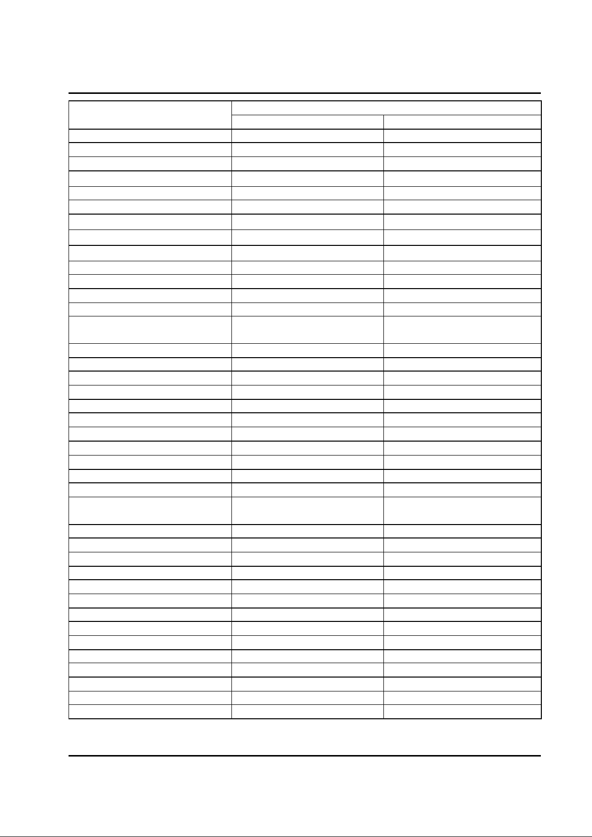
The low pass filter shall satisfy the following parametric limits with a complex impedance ZL
shown in this table across the Line side of this device .
The following requirement is specified for a single splitter.
YCL RDPS-POTS044(R3)
Page 3
0.1uF
0.1uF
100 ohm
0.47mH
Phone-N
Line-P
Phone-P
0.12uF* 2
Line-N
Modem
3
4
Modem-N
Modem-P
RJ11 jack
Page 5
CPF100F
Electrical requirements
Splitter parameter
Range values
Frequency range
Splitter bandwidth DC to 3.4KHz
Nominal voice band 0.3KHz to 3.4KHz
Billing tone
12KHz±80Hz
Ringing frequency 15.3Hz to 68Hz
ADSL band 30KHz to 1104KHz
Line Impedance ZL
270ohm + (750ohm || 150nF)
CO impedance ZTc
270ohm + (750ohm || 150nF)
RT impedance ZTr
270ohm + (750ohm || 150nF)
Modem impedance 30KHz< f< 1104KHz 100 ohm
Operation voltage voice band
Nominal signal 21mVpp to 5.4 Vpp
Billing tone 10Vpp to 30.2Vpp
Ringing signal 40Vrms to 150Vrms(113Vpp to
424 Vpp)
DC voltage 0V to 105V(for ANSI 6.98)
Max. AC voltage 150Vrms with -105VDC offset
Max. differential 320V
Current voice band
Loop current <100mA
Transient current(on/off hook)
400msec <150mA
DC Resistance
DC Resistance <=25 ohm
Isolation resistance tip/ring >5 Mohm
Voice –band characteristic
Insertion loss 1004Hz <1.2 dB
Attenuation distortion(relative to
1004Hz)
200Hz<f<4KHz
<±1.0 dB
Delay distortion 200Hz<f<4KHz <250 usec
Return loss 200Hz<f<500Hz >=14dB
500Hz<f<2KHz >=18dB
2KHz<f<3.4KHz >=14dB
Return loss billing tone 12KHz+/-1KHz >=12dB
Longitudinal conversion loss LCL 200Hz to 3KHz >45 dB
Line Interface
Return Loss Voice band 200Hz<f<500Hz >=14dB
500Hz<f<2KHz >=18dB
2KHz<f<3.4KHz >=14dB
ADSL modem interface
Isolation voltage >2000Vrms for 1 minute
ADSL band characteristic
Stop band attenuation 30KHz<f<1104KHz >45 dB
YCL RDPS-POTS044(R3)
Page 4
Page 6

CPF100F
4.4 : DC characteristic
All requirement of this specification can be met in the presence of all POTS loop currents from
0mA to 100mA. This in line filter can pass POTS tip-to-ring dc voltages of 0V to 105V and
ringing signals of 40V to 150Vrms at any frequency from15.3Hz to 68Hz with a dc component in
the range from 0V to 105V.
The dc resistance from tip-to-ring at the line port interface with the phone interface shorted, shall
be less than or equal to 25 ohms for one splitter.
The DC resistance from tip-to-ground and from ring-to-ground at the POTS interface with the
U-R interface open shall be greater than or equal to 5 Megohms.
The ground point shall be local building or green wire ground. As an objective , the dc resistance
should exceed 10MΩ.
4.5 : Test method
4.5.1 : Insertion loss
The insertion loss of a device connected into a given transmission system is defined as the ratio,
expressed in dB, of the load power available(before and after insertion ) delivered to the output
network beyond the point of insertion at a given frequency.
In general , the insertion loss of a device inserted in a given transmission system mainly caused by
internal component resistive loss while all of the impedance between source , load and device
interface having been matched. To perform the insertion loss measurement ,thru calibration must
be done prior the testing .
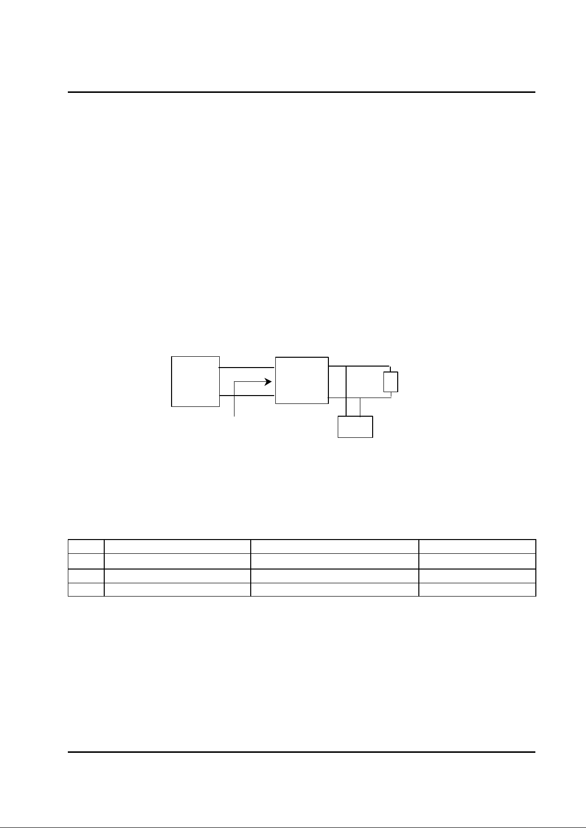
General Insertion loss equation can be expressed as following
Insertion loss = 20 log V2 / V1 dB where
V1 = the measured voltage value of load without LPF in circuit.
V2 = the measured voltage value of load with LPF in circuit.
The test setup is shown in drawing below. :
YCL RDPS-POTS044(R3)
Page 5
POTS
Splitter
Function
Generator
ZL
ZL
HP-r
Page 7
CPF100F
4.5.2 : Return loss :
Return loss measure the amount of energy that is lost due to reflection which resulted from
impedance mismatching at the interface. Return loss is essentially defined as the ratio of the power
incident upon a given transmission system to the power reflected caused by impedance mismatch
with respect to reference impedance at the interface between source and device.
Return loss figure are a function of the impedance of the circuit involved and are therefore frequency
dependent.
These impedance must be closely maintained in order to reduce the possibility of undesirable
reflection and echoes which in long distance circuit the telephone user or destroy the data being sent.
To perform the return loss test ,open ,short, load calibration must be done prior measurement while
the LCZ impedance Analyzer being selected in impedance mode. Return loss is general expressed in
decibels. General Return loss equation as below: Return loss = 20 log ZL + ZM / ZL - ZMdB
Where ZL = the reference impedance ZM = the measured impedance
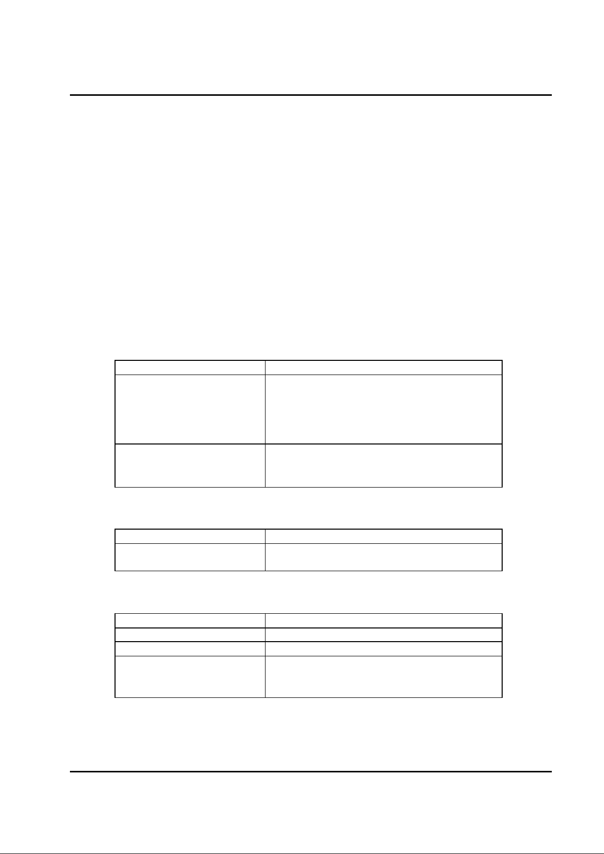
The test setup is shown in drawing below:
5 . Environmental condition
5.1 : EMC , surge and power- contact
The splitter has to comply with EMC Requirements as per ITU K21, so the following
requirements must be taken into consideration:
No Test Test specification Number of tests
1 Lightning surge simulation
1500V , 10/700µs , 200ms
10
2 Power induction 600V , 1s 5
3 Power contact 230V , 15 minute 1
YCL RDPS-POTS044(R3)
Page 6
Z
M
Line
LPFLCZ meter ZL
Phone
HP-r
Page 8
CPF100F
5.2 : Climatic condition
5.2.1 : Operating temperature :
Application indoor
Low ambient temperature - 50C
High ambient temperature +450C
(according to ETS 300 019, class 3.2)
5.2.2 : Storage and Transport :
Low ambient temperature - 400C
High ambient temperature +850C
(according to ETS 300 019, transport: class 2.3, storage: class 1.2)
6. Mechanical condition
6.1 : Operation
Test Test specification
Vibration sinusoidal IEC 68 Part 2-6
10 to 58Hz 0,075mm
58 to 500Hz 10m/S2 ,
1octaver/minute
3 axis; every 10 cycles
Shock(half sine) IEC 68 Part 2-27
≤100kg 100m/ S
2
11ms
6 directions; every 3 shocks
6.2 : Handling
Test Test specification
Freefall IEC 68 Part 2-32 Stand alone:<10kg 75mm
Built in:2x ground area
6.3 : Storage and Transport
Test Test specification
Vibration(random) IEC 68 Part 2-64
Bump IEC 68 Part 2-29
Freefall IEC 68 Part 2-32 <10kg 800mm
Twice at any possible
Transport position on concrete floor
YCL RDPS-POTS044(R3)
Page 7
Page 9

CPF100F
6.4 : Product safety
Test Test specification
Electrical hazard
EN 60950 (A4), (≡VDE 0805)
Mechanical hazard
EN 60950 (A4), (≡VDE 0805)
Fire hazard
EN 60950 (A4), (≡VDE 0805)
7 . Mechanical Condition
7.1 : PCB
7.2 : Mechanical :
YCL RDPS-POTS044(R3)
Page 8
A view
A view
 Loading...