

Page 1

ALUMINUM ELECTROLYTIC CAPACITOR
SURFACE MOUNT TYPE
PART NUMBER DESCRIPTION (for order booking)
Type Rated Cap. Cap. Tol. Rated Voltage Case Size
(1) (2) (3) (4) (5)
Example:
Case Size (D
35V DC
±20%
100μF
Type V
(1) Type: Please refer to “INDEX” shown in page EC-1
(2) Rated Capacitance: inμF
(3) Rated Voltage: in volts (V), DC
(4) Capacitance Tolerance: K=±10%, M=±20%
(5) Case Size: indicating diameter (D) and length (L) in mm.
V 100 M 35V 8x10
ψx L)
Marking: Each capacitor shall be marked with the following information
Example:
4a Date code
1st digit denotes year 2004
2nd digit denotes month of production
VEJ Type*: VJ
*(marking omitted if can size < 8mm)
Rated capacitance: 220µF
220
6.3V Rated voltage: 6.3V
EC-47
Page 2

ALUMINUM ELECTROLYTIC CAPACITOR
TYPE V
SURFACE MOUNT TYPE, 85℃ 2000 HOURS
SPECIFICATIONS:
Item Characteristic
Operating Temperature
Range
Capacitance tolerance ±20% at 120 Hz, 20℃
Leakage Current
(I=DC Current in μA max.)
max at 120 Hz, 20℃
Impedance Ratio at
Low Temperature at 120 Hz
Load Life Test
(restored to 20℃, after 2000
hours application of the rated
voltage at 85℃)
Shelf Life Test
(after 1000 hours exposing
at 85℃ without voltage
applied)
Ripple Current &
Frequency Multipliers
Standards Satisfies Characteristic of JIS C 5101-1, -18
I≦0.01CV or 3μA , whichever is greater, measured after 2 minutes application of
rated working voltage. Where, C =Rated Capacitance (μF)
W. V. 6.3V 10V 16V 25V 35V 50V 63V 100VDissipation Factor ( tanδ)
Tanδ(max) 0.28 0.24 0.20 014 0.12 0.10 0.10 0.10
W.V. 6.3V 10V 16V 25V 35V 50V 63V 100V
Z@ -25℃ / Z@ +20℃ 4 3 2 2 2 2 2 2
Z@ -40℃ / Z@ +20℃ 8 5 4 3 3 3 3 3
The capacitor shall meet following limits:
Capacitance Change ≦±20% of initial value
Leakage Current ≦ specified maximum value
Dissipation Factor ≦ 200% of specified maximum value
Same test results as of load life test
w.v. Freq 50 Hz 120 Hz 1KHz 10KHz up
Under 16V 0.8 1.0 1.15 1.25
25V~ 35V 0.8 1.0 1.25 1.40
50V ~ 63V 0.8 1.0 1.35 1.50
100V 0.7 1.0 1.35 1.50
-40℃ to +85℃
V =Rated Working Voltage (V DC)
EC-48
Page 3

ALUMINUM ELECTROLYTIC CAPACITOR
TYPE V
SURFACE MOUNT TYPE, 85℃ 2000 HOURS
ψD
8
8
L A B C W
6.5±0.3
10±0.5
8.4 8.4 3.0 0.5 TO 0.8 2.3
8.4 8.4 3.0 0.7 TO 1.1 3.1
Unit: mm
P±0.2
10
10±0.5
10.4 10.4 3.3 0.7 TO 1.1 4.7
CASE SIZE (DxL mm) AND PERMISSIBLE RIPPLE CURRENT (mA rms, at 85℃ 120 Hz):
W.V.
μF DxL R.C. DxL R.C. DxL R.C. DxL R.C. DxL R.C. DxL R.C. DxL R.C. DxL R.C.
10 8X6.5 75 8x10 94
22 8x6.5 155 8x10 139 10x10 189
33 8x6.5 155 8x6.5 155 8x10 139 10x10 189
47 8x6.5 155 8x6.5 155 8x10 252 10x10 226
68 10x10 226
100 8x6.5 155 8x6.5 155 8x6.5 155 8x10 252 10x10 458
220 8x6.5 155 8x6.5 155 8x10 252 8x10 252 10x10 458
330 8x6.5 155 8x10 252 8x10 252 10x10 458
470 8x10 252 10x10 458 10x10 458
1000 10x10 458 10X10 458
6.3V 10V 16V 25V 35V 50V 63V
100V
EC-49
Page 4
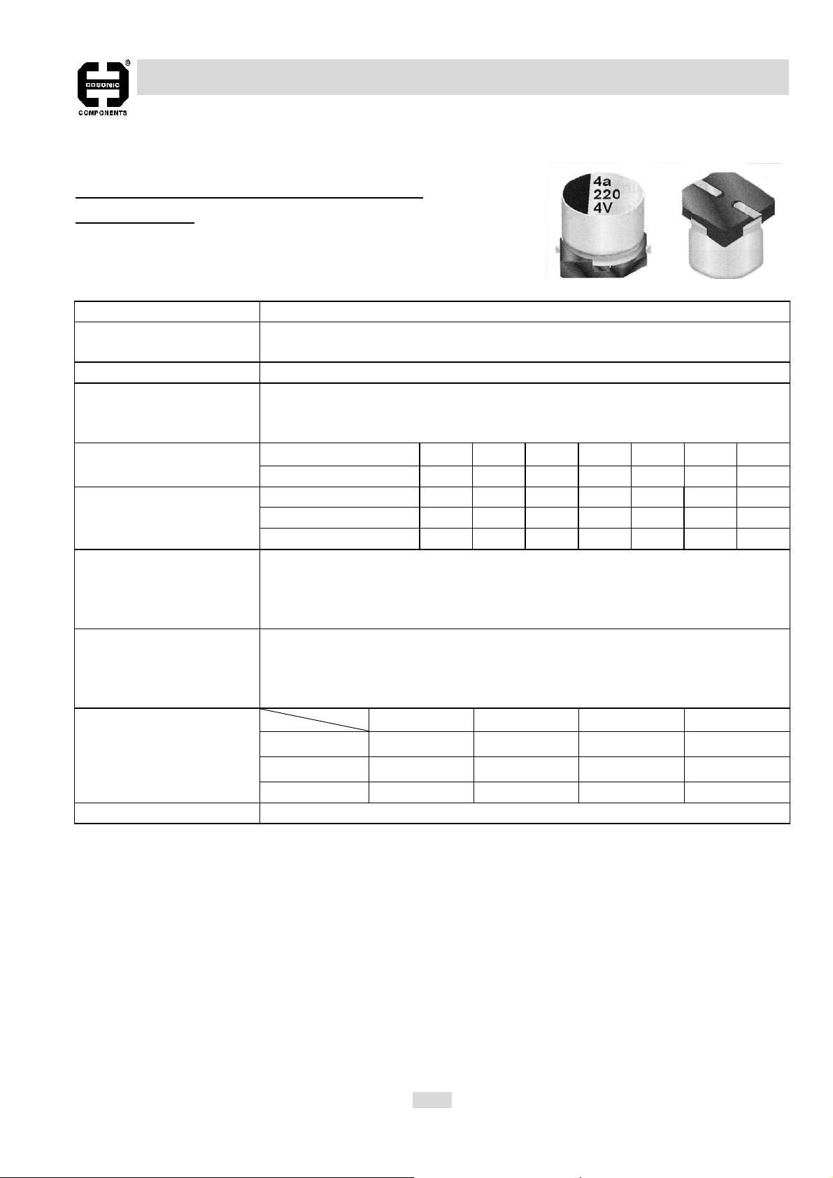
ALUMINUM ELECTROLYTIC CAPACITOR
TYPE V2
SURFACE MOUNT TYPE, 85℃ 2000 HOURS
5.5MM HEIGHT
SPECIFICATIONS:
Item Characteristic
Operating Temperature
Range
Capacitance tolerance ±20% at 120 Hz, 20℃
Leakage Current
(I=DC Current in μA max.)
max at 120 Hz, 20℃
Impedance Ratio at
Low Temperature at 120 Hz
Load Life Test
(restore to 20℃, after 2000
hours application of the rated
voltage at 85℃)
Shelf Life Test
(restore to 20℃, after 1000
hours exposing at 85℃
without voltage applied)
Ripple Current &
Frequency Multipliers
I≦0.01CV or 3μA , whichever is greater, measured after 2 minutes application of
rated working voltage. Where, C =Rated Capacitance (μF)
W. V. 4V 6.3V 10V 16V 25V 35V 50V Dissipation Factor ( tanδ)
Tanδ(max) 0.42 0.28 0.24 0.20 0.14 0.12 0.10
W.V. 4V 6.3V 10V 16V 25V 35V 50V
Z@ -25℃ / Z@ +20℃ 7 3 3 2 2 2 2
Z@ -40℃ / Z@ +20℃ 15 8 5 4 3 3 3
The capacitor shall meet following limits:
Capacitance Change ≦±20% of initial value (4W.V.: ±30%)
Dissipation Factor ≦ 200% of specified maximum value (4W.V.: 300%)
Leakage Current ≦ specified maximum value
Same test results as of load life test
w.v. Freq 50 Hz 120 Hz 1KHz 10KHz up
Under 16V 0.8 1.0 1.15 1.25
25V~ 35V 0.8 1.0 1.25 1.40
-40℃ to +85℃
V =Rated Working Voltage (V DC)
50V ~ 63V 0.8 1.0 1.35 1.50
Standards Satisfies Characteristic of JIS C 5101-1, -18
EC-50
Page 5
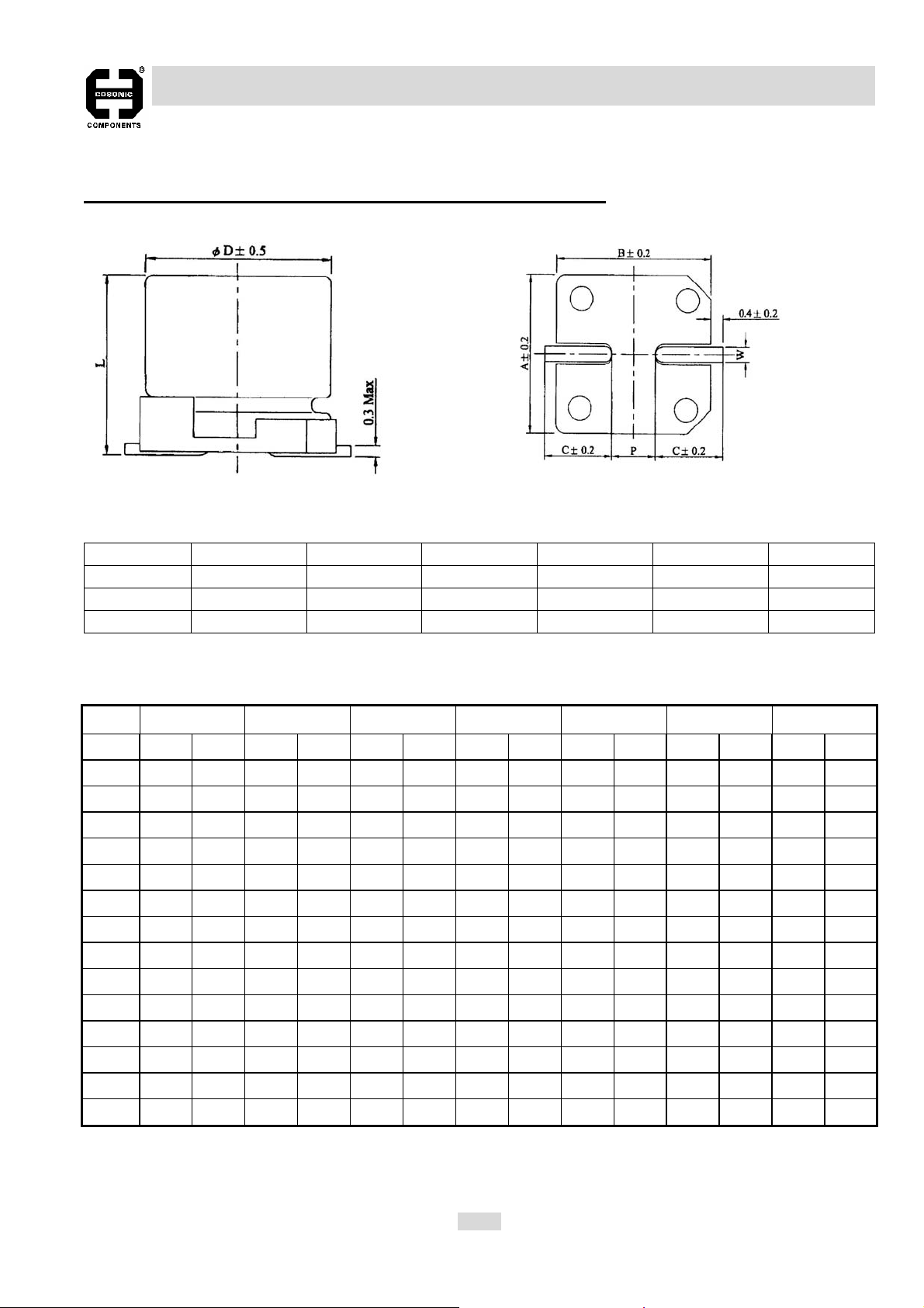
ALUMINUM ELECTROLYTIC CAPACITOR
TYPE V2
SURFACE MOUNT TYPE, 85℃ 2000 HOURS 5.5MM HEIGHT
Unit: mm
Dψ L A B C W P±0.2
4.0 5.3±0.2 4.3 4.3 2.0 0.5 to 0.8 1.0
5.0 5.3±0.2 5.3 5.3 2.3 0.5 to 0.8 1.5
6.3 5.3±0.2 6.6 6.6 2.7 0.5 to 0.8 2.0
CASE SIZE (DxL mm) AND PERMISSIBLE RIPPLE CURRENT (mA rms, at 85℃ 120 Hz):
W.V. 4V 6.3V 10V 16V 25V 35V 50V
μF DxL R.C. DxL R.C. DxL R.C. DxL R.C. DxL R.C. DxL R.C. DxL R.C.
0.1 4x5.33
0.22 4x5.35
0.33 4x5.36
0.47 4x5.37
1.0 4x5.310
2.2 4x5.315
3.3 4x5.319
4.7 4x5.3 19 4x5.3 20 4x5.3 26
10 4x5.3 23 4x5.3 26 5x5.3 32 5x5.3 34 6.3x5.3 44
22 4x5.3 31 5x5.3 39 5x5.3 44 6.3x5.3 55 6.3x5.3 59
33 4x5.3 31 5x5.3 44 5x5.3 48 6.3x5.3 63 6.3x5.3 67
47 4x5.3 37 5x5.3 52 6.3x5.3 67 6.3x5.3 75
100 5x5.3 63 6.3x5.3 89 6.3x5.3 98 6.3x5.3 103
220 6.3x5.3 110 6.3x5.3 120
EC-51
Page 6
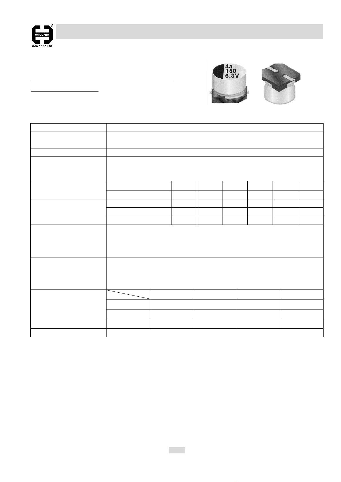
ALUMINUM ELECTROLYTIC CAPACITOR
TYPE V3
SURFACE MOUNT TYPE, 85℃ 2000 HOURS
5.5MM, 8MM HEIGHT
SPECIFICATIONS:
Item Characteristic
Operating Temperature
Range
Capacitance tolerance ±20% at 120 Hz, 20℃
Leakage Current
(I=DC Current in μA max.)
max at 120 Hz, 20℃
Impedance Ratio at
Low Temperature at 120 Hz
Load Life Test
(restore to 20℃, after 2000
hours application of the rated
voltage, at 85℃)
Shelf Life Test
(restore to 20℃, after 1000
hours exposing at 85℃
without voltage applied)
Ripple Current &
Frequency Multipliers
I≦0.01CV or 3μA , whichever is greater, measured after 2 minutes application of
rated working voltage. Where, C =Rated Capacitance (μF)
W. V. 6.3V 10V 16V 25V 35V 50V Dissipation Factor ( tanδ)
Tanδ(max) 0.42 0.32 0.26 0.18 0.14 0.12
W.V. 6.3V 10V 16V 25V 35V 50V
Z@ -25℃ / Z@ +20℃ 4 3 2 2 2 2
Z@ -40℃ / Z@ +20℃ 8 8 5 5 4 4
The capacitor shall meet following limits:
Capacitance Change ≦±30% of initial value
Dissipation Factor ≦ 300% of specified maximum value
Leakage Current ≦ specified maximum value
Same test results as of load life test
w.v. Freq 50 Hz 120 Hz 1KHz 10KHz up
Under 16V 0.8 1.0 1.15 1.25
25V~ 35V 0.8 1.0 1.25 1.40
-40℃ to +85℃
V =Rated Working Voltage (V DC)
50V ~ 63V 0.8 1.0 1.35 1.50
Standards Satisfies Characteristic of JIS C 5101-1, -18
EC-52
Page 7

ALUMINUM ELECTROLYTIC CAPACITOR
TYPE V3
SURFACE MOUNT TYPE, 85℃ 2000 HOURS; 5.5MM, 8MM HEIGHT
Dψ L A B C W P±0.2
4.0 5.3±0.2 4.3 4.3 2.0 0.5 to 0.8 1.0
5.0 5.3±0.2 5.3 5.3 2.3 0.5 to 0.8 1.5
6.3 5.3±0.2 6.6 6.6 2.7 0.5 to 0.8 2.0
6.3 7.7±0.2 6.6 6.6 2.7 0.5 to 0.8 2.0
CASE SIZE (DxL mm) AND PERMISSIBLE RIPPLE CURRENT (mA rms, at 85℃ 120 Hz):
Unit: mm
W.V. 6.3V 10V 16V 25V 35V 50V
μF DxL R.C. DxL R.C. DxL R.C. DxL R.C. DxL R.C. DxL R.C.
4.7 4x5.3 20
10 4x5.3 27 5x5.3 34
22 4x5.3 30 6.3x5.3 47 6.3x5.3 59
33 4x5.3 33 5x5.3 54 6.3x5.3 67 6.3x7.7 82
47 4x5.3 34 5x5.3 50 6.3x5.3 75 6.3x7.7 98
68 5x5.3 54 6.3x5.3 90 6.3x7.7 109
100 5x5.3 58 5x5.3 65 6.3x7.7 124
150 6.3x5.3 83 6.3x5.3 109
220 63x7.7 130
330 63x7.7 139
EC-53
Page 8

ALUMINUM ELECTROLYTIC CAPACITOR
TYPE VS
SURFACE MOUNT TYPE, 105℃ 1000 HOURS
5.5MM HEIGHT
SPECIFICATIONS:
Item Characteristic
Operating Temperature
Range
Capacitance tolerance ±20% at 120 Hz, 20℃
Leakage Current
(I=DC Current in μA max.)
max at 120 Hz, 20℃
Impedance Ratio at
Low Temperature at 120 Hz
Load Life Test
(restore to 20℃, after 1000
hours application of the rated
voltage at 105℃)
Shelf Life Test
(restore to 20℃, after 1000
hours exposing at 85℃
without voltage applied)
Ripple Current &
Frequency Multipliers
I≦0.01CV or 3μA , whichever is greater, measured after 2 minutes application of
rated working voltage. Where, C =Rated Capacitance (μF)
W. V. 6.3V 10V 16V 25V 35V 50V Dissipation Factor ( tanδ)
Tanδ(max) 0.30 0.26 0.22 0.16 0.13 0.12
W.V. 6.3V 10V 16V 25V 35V 50V
Z@ -25℃ / Z@ +20℃ 4 3 2 2 2 2
Z@ -40℃ / Z@ +20℃ 8 5 4 3 3 3
The capacitor shall meet following limits:
Capacitance Change ≦±20% of initial value
Dissipation Factor ≦ 200% of specified maximum value
Leakage Current ≦ specified maximum value
Same test results as of load life test
w.v. Freq 50 Hz 120 Hz 1KHz 10KHz up
Under 16V 0.8 1.0 1.15 1.25
25V~ 35V 0.8 1.0 1.25 1.40
-55℃ to +105℃
V =Rated Working Voltage (V DC)
50V 0.8 1.0 1.35 1.50
Standards Satisfies Characteristic of JIS C 5101-1, -18
EC-54
Page 9

ALUMINUM ELECTROLYTIC CAPACITOR
TYPE VS
SURFACE MOUNT TYPE, 105℃ 1000 HOURS 5.5MM HEIGHT
Unit: mm
Dψ L A B C W P±0.2
4.0 5.3±0.2 4.3 4.3 2.0 0.5 to 0.8 1.0
5.0 5.3±0.2 5.3 5.3 2.3 0.5 to 0.8 1.5
6.3 5.3±0.2 6.6 6.6 2.7 0.5 to 0.8 2.0
CASE SIZE (DxL mm) AND PERMISSIBLE RIPPLE CURRENT (mA rms, at 105℃ 120 Hz):
W.V.
μF DxL R.C. DxL R.C. DxL R.C. DxL R.C. DxL R.C. DxL R.C.
0.1 4x5.32
0.22
0.33
0.47
1
2.2
3.3
4.7 4x5.3 12 4x5.7 14
10 4x5.3 15 4x5.3 16 5x5.3 21 5x5.7 23 6.3x5.7 26
22 4x5.3 21 5x5.3 25 5x5.3 28 6.3x5.3 36 6.3x5.7 50 6.3x5.7 51
33 5x5.3 30 6.3x5.3 31 6.3x5.3 40 6.3x5.3 44
47 6.3x5.3 36 6.3x5.3 43 6.3x5.3 47 6.3x5.3 60
100 6.3x5.3 61 6.3x5.3 65 6.3x5.3 70
6.3V 10V 16V 25V 35V 50V
4x5.3
4x5.3
4x5.3
4x5.3
4x5.3
4x5.3
5x5.3
3
4
5
7
10
12
17
EC-55
Page 10

ALUMINUM ELECTROLYTIC CAPACITOR
TYPE VL
SURFACE MOUNT TYPE 105℃ 2000 HOURS,
6MM HEIGHT
SPECIFICATIONS:
Item Characteristic
Operating Temperature
Range
Capacitance tolerance ±20% at 120 Hz, 20℃
Leakage Current
(I=DC Current in μA max.)
max at 120 Hz, 20℃
Impedance Ratio at
Low Temperature at 120 Hz
The capacitor shall meet following limits:
Load Life Test
(restore to 20℃, after 2000
hours application of the rated
voltage at 105℃)
Shelf Life Test
(restore to 20℃, exposing
1000 hours at 105℃without
voltage applied)
Ripple Current &
Frequency Multipliers
Standards Satisfies Characteristic W of JIS C 5101-1, -18
I≦0.01CV or 3μA , whichever is greater, measured after 2 minutes application of
rated working voltage. Where, C =Rated Capacitance (μF)
W. V. 6.3V 10V 16V 25V 35V 50V Dissipation Factor ( tanδ)
Tanδ(max) 0.32 0.28 0.24 018 0.15 0.14
W.V. 6.3V 10V 16V 25V 35V 50V
Z@ -25℃/ Z@ +20℃ 4 3 2 2 2 2
Z@ -40℃/ Z@ +20℃ 8 5 4 3 3 3
6.3V ≦±30% of initial value
Capacitance Change
Dissipation Factor
Leakage Current ≦ specified maximum value
Same test results as of load life test
w.v. Freq 50/60 Hz 120 Hz 1KHz 10KHz up
Under 16V 0.8 1.0 1.15 1.25
25V~ 35V 0.8 1.0 1.25 1.40
50V
0.1~ 0.33μF 0.5 1.0 1.35 1.50
4.7~ 10μF 0.7 1.0 1.35 1.50
10 ~16V ≦±25% of initial value
25 ~ 100V ≦±20% of initial value
6.3 ~16V ≦±300% of specified value
25 ~ 100V ≦±200% of specified value
-55℃ to +105℃
V =Rated Working Voltage (V DC)
EC-56
Page 11
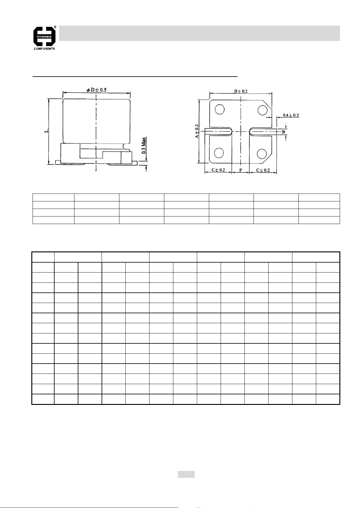
ALUMINUM ELECTROLYTIC CAPACITOR
TYPE VL
SURFACE MOUNT TYPE, 105℃ 2000 HOURS, 6MM HEIGHT
Unit: mm
Dψ L A B C W P±0.2
4.0 5.7±0.2 4.3 4.3 2.0 0.5 to 0.8 1.0
5.0 5.7±0.2 5.3 5.3 2.3 0.5 to 0.8 1.5
6.3 5.7±0.2 6.6 6.6 2.7 0.5 to 0.8 2.0
CASE SIZE (DxL mm) AND PERMISSIBLE RIPPLE CURRENT (mA rms, at 105℃ 120 Hz):
W.V.
μF DxL R.C. DxL R.C. DxL R.C. DxL R.C. DxL R.C. DxL R.C.
0.1 4x5.72
0.22 4x5.73
0.33 4x5.74
0.47 4x5.75
1 4x5.7 10
2.2 4x5.7 16
3.3 4x5.7 18
4.7 4x5.7 13 4x5.7 15 5x5.7 22
10 4x5.7 16 5x5.7 23 5x5.7 25 6.3x5.7 30
22 5x5.7 30 6.3x5.7 38 6.3x5.7 50
33 6.3x5.7 40 6.3x5.7 46
47 6.3x5.7 43 6.3x5.7 50 6.3x5.3 56
100 6.3x5.7 61
6.3V 10V 16V 25V 35V 50V
EC-57
Page 12
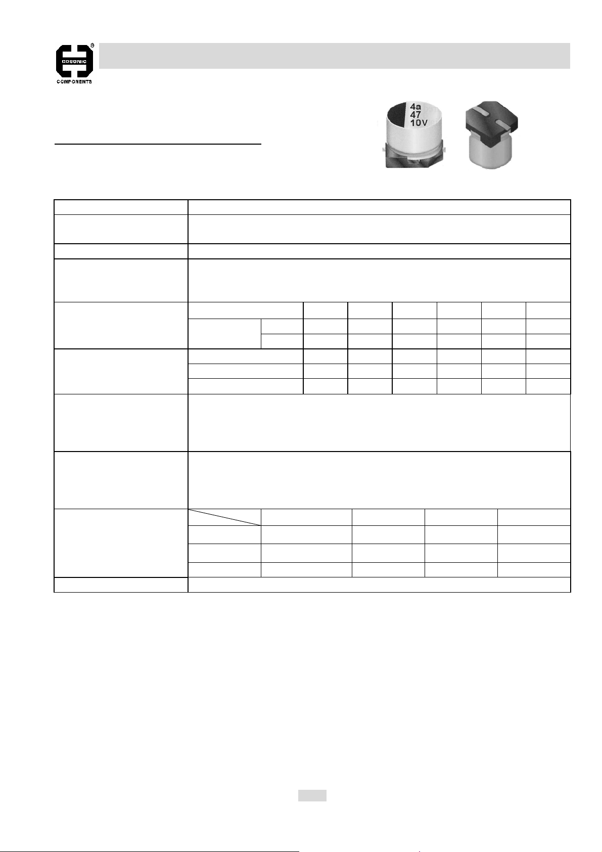
ALUMINUM ELECTROLYTIC CAPACITOR
TYPE VB
SURFACE MOUNT TYPE, BI-POLAR
SPECIFICATIONS:
Item Characteristic
Operating Temperature
Range
Capacitance tolerance ±20% at 120 Hz, 20℃
Leakage Current
(I=DC Current in μA max.)
Dissipation Factor ( tanδ)
max at 120 Hz, 20℃
Impedance Ratio at
Low Temperature at 120 Hz
Load Life Test
(restore to 20℃, after 2000
hours application of the rated
voltage, at 85℃)
Shelf Life Test
(restore to 20℃, after 1000
hours exposing at 85℃
without voltage applied)
Ripple Current &
Frequency Multipliers
I≦0.01CV or 3μA , whichever is greater, measured after 2 minutes application of
rated working voltage. Where, C =Rated Capacitance (μF)
W. V. 6.3V 10V 16V 25V 35V 50V
Tanδ(max)
W.V. 6.3V 10V 16V 25V 35V 50V
Z@ -25℃ / Z@ +20℃ 3 3 2 2 2 2
Z@ -40℃ / Z@ +20℃ 8 5 4 3 3 3
The capacitor shall meet following limits:
Capacitance Change ≦±20% of initial value
Dissipation Factor ≦ 200% of specified maximum value
Leakage Current ≦ specified maximum value
Same test results as of load life test
w.v. Freq 50 Hz 120 Hz 1KHz 10KHz up
Under 16V 0.8 1.0 1.15 1.25
25V~ 35V 0.8 1.0 1.25 1.40
4φ 0.35 0.30 0.25 0.25 0.25 0.25
5~6.3φ 0.30 0.25 0.20 0.15 0.15 0.15
-40℃ to +85℃
V =Rated Working Voltage (V DC)
50V 0.8 1.0 1.35 1.50
Standards Satisfies Characteristic of JIS C 5101-1, -18
EC-58
Page 13
ALUMINUM ELECTROLYTIC CAPACITOR
TYPE VB
SURFACE MOUNT TYPE, BI-POLAR
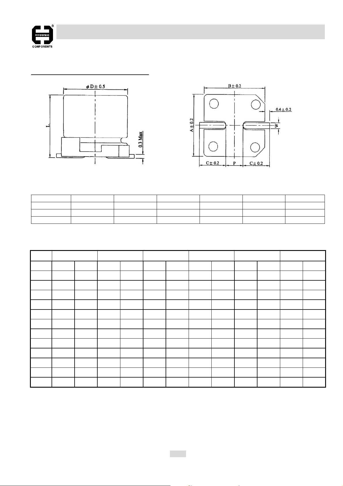
Dψ L A B C W P±0.2
4.0 5.3±0.2 4.3 4.3 2.0 0.5 to 0.8 1.0
5.0 5.3±0.2 5.3 5.3 2.3 0.5 to 0.8 1.5
6.3 5.3±0.2 6.6 6.6 2.7 0.5 to 0.8 2.0
CASE SIZE (DxL mm) AND PERMISSIBLE RIPPLE CURRENT (mA rms, at 85℃ 120 Hz):
Unit: mm
W.V. 6.3V 10V 16V 25V 35V 50V
μF DxL R.C. DxL R.C. DxL R.C. DxL R.C. DxL R.C. DxL R.C.
0.1 4x5.32.3
0.22 4x5.33.3
0.33 4x5.34.1
0.47 4x5.34.9
1.0 4x5.37.2
2.2 4x5.3 10 5x5.3 14
3.3 4x5.3 13 5x5.3 17 5x5.3 17
4.7 4x5.3 14 5x5.3 20 5x5.3 21 6.3x5.3 24
10 4x5.3 18 5x5.3 26 6.3x5.3 35 6.3x5.3 35
22 5x5.3 27 6.3x5.3 40 6.3x5.3 45
33 6.3x5.3 45 6.3x5.3 50 6.3x5.3 55
47 6.3x5.3 54
EC-59
Page 14

ALUMINUM ELECTROLYTIC CAPACITOR
TYPE VJ
SURFACE MOUNT TYPE, 105℃ 2000 HOURS
SPECIFICATIONS:
Item Characteristic
Operating Temperature
Range
Capacitance tolerance ±20% at 120 Hz, 20℃
Leakage Current
(I=DC Current in μA max.)
max at 120 Hz, 20℃
Impedance Ratio at
Low Temperature at 120 Hz
The capacitor shall meet following limits:
Load Life Test
(restore to 20℃, after 2000
hours application of the rated
voltage at 105℃)
Shelf Life Test
(restore to 20℃, exposing
1000 hours at 105℃without
voltage applied)
Ripple Current &
Frequency Multipliers
Standards Satisfies Characteristic of JIS C 5101-1, -18
I≦0.01CV or 3μA , whichever is greater, measured after 2 minutes application of
rated working voltage. Where, C =Rated Capacitance (μF)
W. V. 6.3V 10V 16V 25V 35V 50V 63V 100VDissipation Factor ( tanδ)
Tanδ(max) 0.30 0.26 0.22 016 0.13 0.12 0.11 0.10
W.V. 6.3V 10V 16V 25V 35V 50V 63V 100V
Z@ -25℃/ Z@ +20℃ 4 3 2 2 2 2 2 2
Z@ -40℃/ Z@ +20℃ 8 5 4 3 3 3 3 3
6.3V ≦±30% of initial value
Capacitance Change
Dissipation Factor
Leakage Current ≦ specified maximum value
Same test results as of load life test
w.v. Freq 50/60 Hz 120 Hz 1KHz 10KHz up
Under 16V 0.8 1.0 1.15 1.25
25V~ 35V 0.8 1.0 1.25 1.40
50V ~ 63V 0.8 1.0 1.35 1.50
100V 0.7 1.0 1.35 1.50
10 ~16V ≦±25% of initial value
25 ~ 100V ≦±20% of initial value
6.3 ~16V ≦±300% of specified value
25 ~ 100V ≦±200% of specified value
-55℃ to +105℃
V =Rated Working Voltage (V DC)
EC-60
Page 15
ALUMINUM ELECTROLYTIC CAPACITOR
TYPE VJ
SURFACE MOUNT TYPE, 105℃ 2000 HOURS
Unit: mm
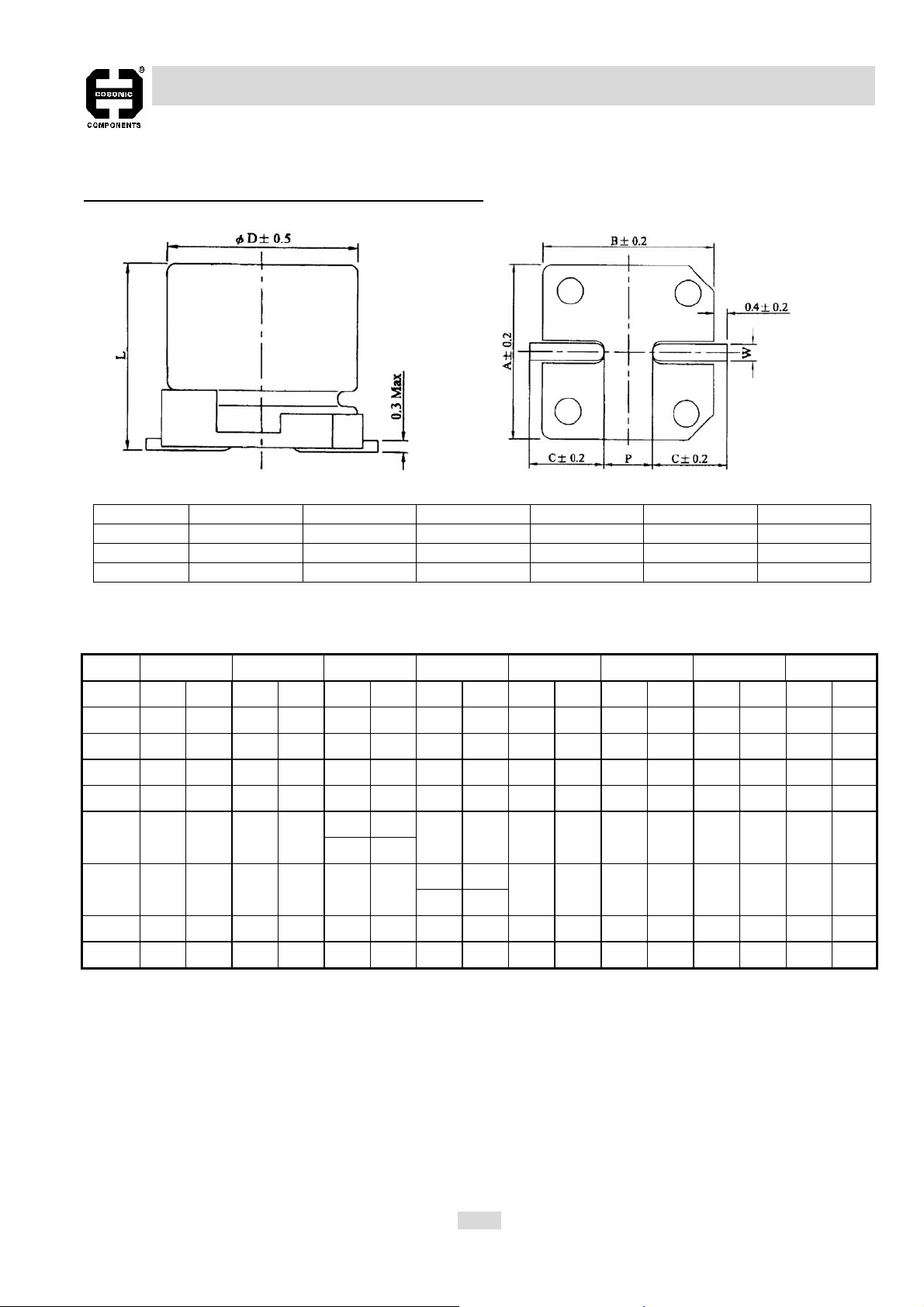
Dψ L A B C W P±0.2
8 6.5±0.3 8.4 8.4 3.4 0.5 to 0.8 2.3
8 10±0.5 8.4 8.4 3.0 0.7 to 1.1 3.1
10 10±0.5 10.4 10.4 3.3 0.7 to 1.1 4.7
CASE SIZE (DxL mm) AND PERMISSIBLE RIPPLE CURRENT (mA rms, at 105℃ 120 Hz):
W.V.
μF DxL R.C. DxL R.C. DxL R.C. DxL R.C. DxL R.C. DxL R.C. DxL R.C. DxL R.C.
10 8X1067
22 8x6.5 110 8X10 99 10X10 133
33 8x6.5 110 8X10 178 10X10 160
47 8X6.5 110 8X10 178 8X10 178 10X10 160
100 8X6.5 110
220 8X10 178 8X10 178 10X10 324
330 8X10 178 10X10 324 10X10 324 10X10 324
470 10X10 324 10X10 324 10X10 324
6.3V 10V 16V 25V 35V 50V 63V 100V
8X6.5 110
8X10 178
8X10 178 10X10 324 10X10 324
8X10 240
10X10 324
10X10 324
EC-61
Page 16
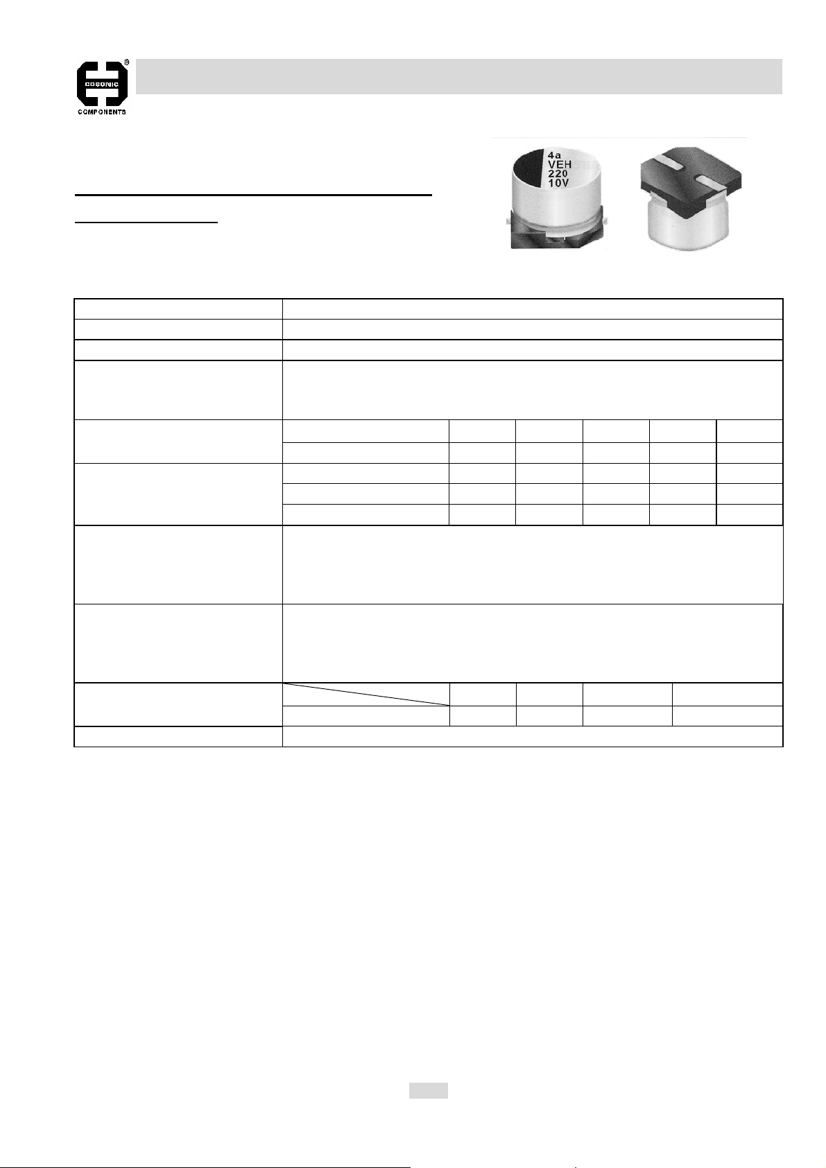
ALUMINUM ELECTROLYTIC CAPACITOR
TYPE VH
SURFACE MOUNT TYPE, 105℃ 2000 HOURS
LOW IMPEDANCE
SPECIFICATIONS:
Item Characteristic
Operating Temperature Range -55℃ to +105℃
Capacitance tolerance ±20% at 120 Hz, 20℃
Leakage Current
(I=DC Current in μA max.)
at 120 Hz, 20℃
Impedance Ratio at
Low Temperature at 120 Hz
Load Life Test
(restore to 20℃, after 2000
hours application of the rated
voltage, at 105℃)
Shelf Life Test
(restore to 20℃, after 1000
hours exposing at 85℃ without
voltage applied)
Ripple Current &
Frequency Multipliers
Standards Satisfies Characteristic of JIS C 5101-1, -18
I≦0.01CV or 3μA , whichever is greater, measured after 2 minutes application
of rated working voltage. Where, C =Rated Capacitance (μF)
V =Rated Working Voltage (V DC)
W. V. 6.3V 10V 16V 25V 35V Dissipation Factor ( tanδ) max
Tanδ(max) 0.30 0.26 0.22 016 0.13
W.V. 6.3V 10V 16V 25V 35V
Z@ -25℃ / Z@ +20℃ 4 3 2 2 2
Z@ -40℃ / Z@ +20℃ 8 5 4 3 3
The capacitor shall meet following limits:
Capacitance Change ≦±20% of initial value
Dissipation Factor ≦ 200% of specified maximum value
Leakage Current ≦ specified maximum value
Same test results as of load life test
w.v. Freq 50/60 Hz 120 Hz 1KHz 10KHz up
6.3V ~ 35V 0.64 0.8 0.93 1.0
EC-62
Page 17
ALUMINUM ELECTROLYTIC CAPACITOR
TYPE VH
SURFACE MOUNT TYPE, 105℃ 1000 HOURS, LOW IMPEDANCE
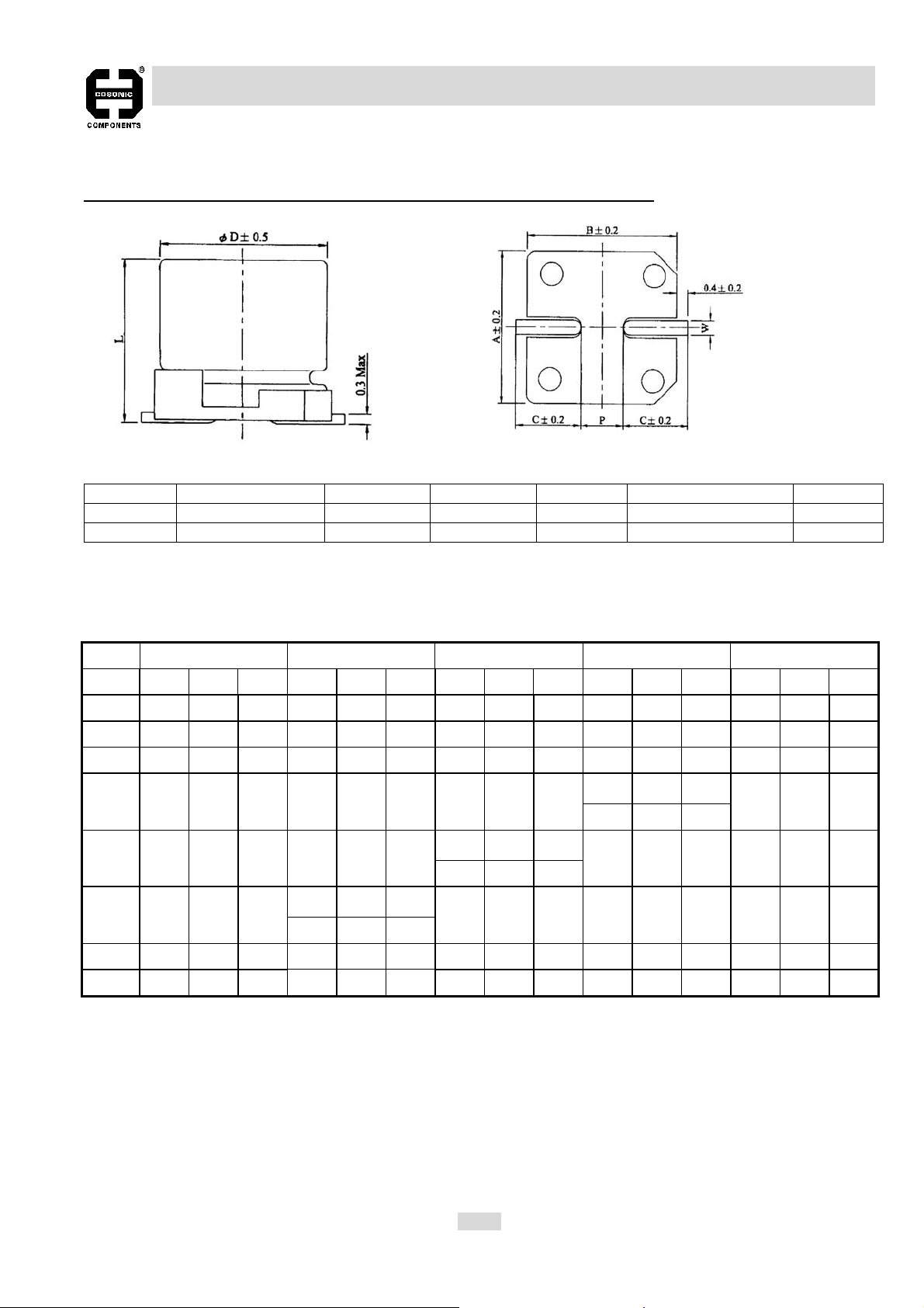
Dψ L A B C W P±0.2
8.0 10 ±0.5 8.4 8.4 3.0 0.7 to 1.1 3.1
10 10 ±0.5 10.4 10.4 3.3 0.7 to 1.1 4.7
CASE SIZE (DxL mm), PERMISSIBLE RIPPLE CURRENT (mA rms, at 105℃100K Hz) AND
Unit: mm
IMPEDANCE (Ohm at 100K Hz, 20℃):
W.V.
μF DxL Imp. R.C. DxL Imp. R.C. DxL Imp. R.C. DxL Imp. R.C. DxL Imp. R.C.
47 8x10 0.45 369
100 8x10 0.45 369 10x10 0.25 553
150 8x10 0.45 369
220 8x10 0.45 369
330 8x10 0.45 369
470 8x10 0.45 369
820 10x10 0.25 553
1000 10x10 0.25 553
6.3V 10V 16V 25V 35V
8x10 0.45 369
10x10 0.25 553
10x10 0.25 553
8x10 0.45 369
10x10 0.25 553
10x10 0.25 553
8x10 0.45 369
10x10 0.25 553
10x10 0.25 553
EC-63
Page 18
ALUMINUM ELECTROLYTIC CAPACITOR
TYPE VZ
SURFACE MOUNT TYPE, 105℃ 1000 HOURS
LOW IMPEDANCE
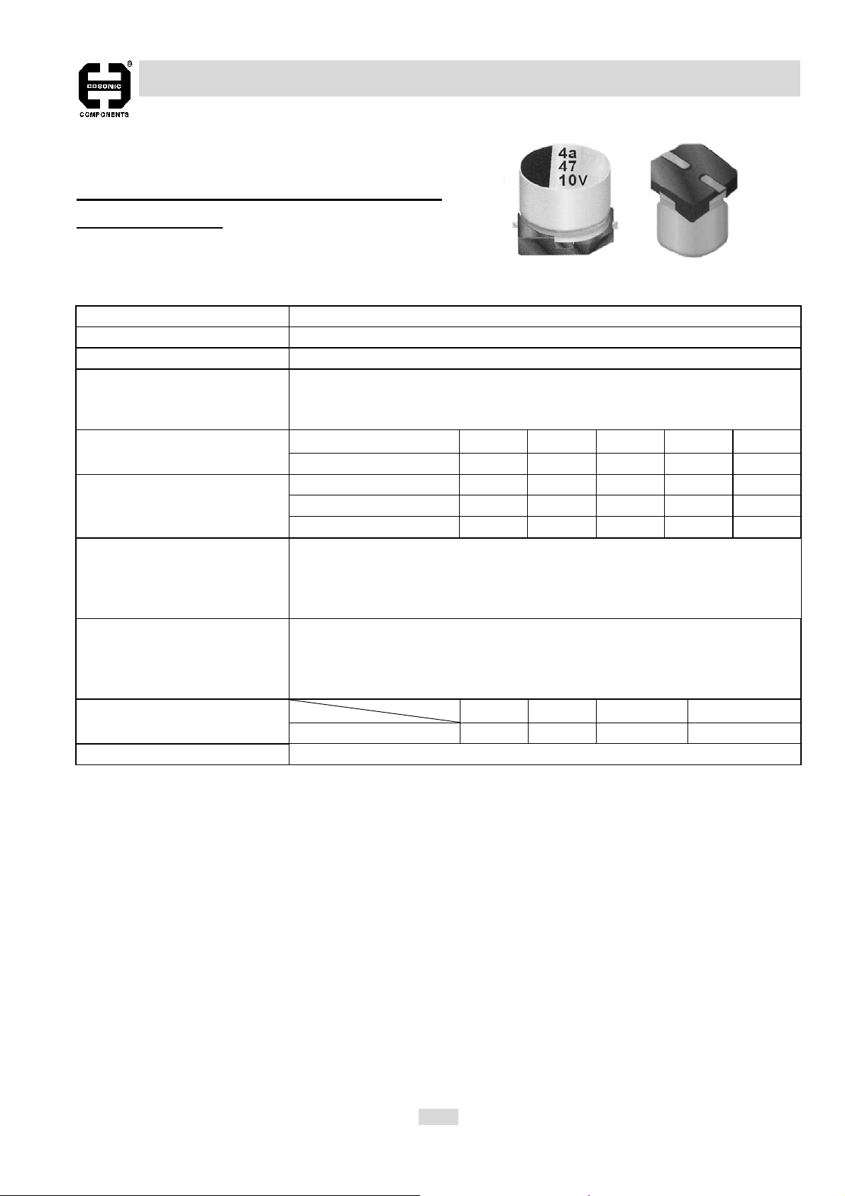
SPECIFICATIONS:
Item Characteristic
Operating Temperature Range -55℃ to +105℃
Capacitance tolerance ±20% at 120 Hz, 20℃
Leakage Current
(I=DC Current in μA max.)
at 120 Hz, 20℃
Impedance Ratio at
Low Temperature at 120 Hz
Load Life Test
(restore to 20℃, after 1000
hours application of the rated
voltage, at 105℃)
Shelf Life Test
(restore to 20℃, after 1000
hours exposing at 85℃ without
voltage applied)
Ripple Current &
Frequency Multipliers
Standards Satisfies characteristic of JIS C 5101-1, -18
I≦0.01CV or 3μA , whichever is greater, measured after 2 minutes application
of rated working voltage. Where, C =Rated Capacitance (μF)
V =Rated Working Voltage (V DC)
W. V. 6.3V 10V 16V 25V 35V Dissipation Factor ( tanδ) max
Tanδ(max) 0.28 0.24 0.20 016 0.14
W.V. 6.3V 10V 16V 25V 35V
Z@ -25℃ / Z@ +20℃ 4 3 2 2 2
Z@ -40℃ / Z@ +20℃ 8 5 4 3 3
The capacitor shall meet following limits:
Capacitance Change ≦±25% of initial value
Dissipation Factor ≦ 200% of specified maximum value
Leakage Current ≦ specified maximum value
Same test results as of load life test
w.v. Freq 50/60 Hz 120 Hz 1KHz 10KHz up
6.3V ~ 35V 0.64 0.8 0.93 1.0
EC-64
Page 19

ALUMINUM ELECTROLYTIC CAPACITOR
TYPE VZ
SURFACE MOUNT TYPE, 105℃ 1000 HOURS, LOW IMPEDANCE
Dψ L A B C W P±0.2
8.0 10 ±0.5 8.4 8.4 3.0 0.7 to 1.1 3.1
10 10 ±0.5 10.4 10.4 3.3 0.7 to 1.1 4.7
CASE SIZE (DxL mm), PERMISSIBLE RIPPLE CURRENT (mA rms, at 105℃100K Hz) AND
Unit: mm
IMPEDANCE (Ohm at 100K Hz, 20℃):
W.V.
μF DxL Imp. R.C. DxL Imp. R.C. DxL Imp. R.C. DxL Imp. R.C. DxL Imp. R.C.
4.7 4X5.3 3.20 65 4X5.3 3.20 65
10 4X5.3 3.20 65 4X5.3 3.20 65 5x5.3 1.50 110 5X5.3 1.50 110
4X5.3 3.20 65 5x5.3 1.50 110 5x5.3 1.50 110 6.3X5.3 0.85 170
22
5x5.3 1.50 110 5x5.3 1.50 110 6.3X5.3 0.85 170
33
5x5.3 1.50 110 6.3X5.3 0.85 170
47
100 6.3X5.3 0.85 170 6.3X5.3 0.85 170 6.3X5.3 0.85 170 6.3X7.7 0.50 255
150 6.3X7.7 0.50 255
220 6.3X7.7 0.50 255
6.3V 10V 16V 25V 35V
6.3X5.3 0.85 170
6.3X5.3 0.85 170 6.3X5.3 0.85 170
6.3X5.3 0.85 170 6.3X5.3 0.85 170 6.3X5.3 0.50 255
EC-65
Page 20

ALUMINUM ELECTROLYTIC CAPACITOR
SURFACE MOUNT TYPE
Recommended pad pattern and size
Recommended soldering methods
Unit: mm
Dφx L
4x5.3 D55 1.6 2.6 1.0
4x5.7 D60 1.6 2.6 1.0
5x5.3 E55 1.6 3.0 1.4
5x5.7 E60 1.6 3.0 1.4
6.3x5.3 F55 1.6 3.5 1.9
6.3x5.7 F60 1.6 3.5 1.9
6.3x7.7 F80 1.6 3.5 1.9
8x6.5 G68 1.6 4.0 2.1
8x10 G10 2.5 3.5 3.0
10x10 H10 2.5 4.0 4.0
(1) Reflow soldering condition.
The following temperature profile condition should be
observed for soldering. (For higher temperature,
pleases contact us after measuring the capacitor’s
product temperature profile at your side.)
Product temperature will rise slower as the product
size gets bigger. It is not necessary to adjust the reflow
furnace temperature setting according to the product
size, for example, φ4 andφ10 products can be mixed
on one PCB for reflowing.
(2) Soldering precautions
1. Elements related to the reflow soldering temperature
*Product size: The temperature rises slower as the
size gets bigger.
*Product location: The center part of the PCB tends
to have a lower temperature than the PCB edges.
*PCB size: The PCB temperature rises slower as the
area and / or thickness of the PCB gets greater.
2. Repeated reflowing
*Avoid reflowing twice if possible.
*If repeated reflowing is unavoidable, contact us after
measuring the first and the second reflow profiles
and reflow interval at your side.
*Do not attempt to reflow three times.
3. Soldering with soldering iron
Observe the following conditions.
*The iron tip temperature : 350 ±5°C
*Soldering time: 3 seconds.
Case
Code
Land Size
X Y W
EC-67
 Loading...