

Page 1
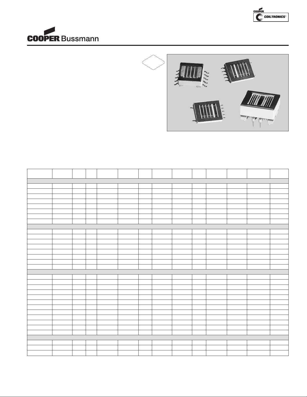
escription
R
oHS
2002/95/EC
D
• Transformers for use in CCFL power supplies,
available in through-hole and surface mount
recess or gull wing versions, incorporating
floating or fixed secondary technology
• Supply output current up to 30 milli-Amps
• Frequency range from 40 to 80 KHz
• Deliver output power from 2.5 to 14 Watts
• Operate in royer and other topologies
• Ferrite core material
Applications
• CCFL power supplies
Environmental Data
• Storage temperature range: -40°C to +85°C
• Operating ambient temperature range: 0°C to +70°C
• Solder reflow temperature: +260°C max. for 10 seconds
max.
CCFL TRANSFORMERS
Cold Cathode Fluorescent
Lamp Inverter Transformers
Packaging
• Supplied in bulk packaging
Part
Number Diagram Watts µH1Ohms Max Ohms Max Ns/Np Volts Max2Volts Max2A rms Abnormal3Abnormal3Dimensions Layout
2.5 WATT VERSIONS
CTX110652-R
CTX110655-R
CTX110657-R
CTX110659-R
CTX210652-R
CTX210655-R
CTX210657-R
CTX210659-R
4 WATT VERSIONS
CTX210403-R C 4 44 0.220 165 50 26 1340 .007 40 2000 C C
CTX210407-R C 4 27 0.160 220 86 15 1340 .007 23 2000 C C
CTX210409-R C 4 20 0.160 220 100 13 1340 .007 23 2000 C C
CTX210411-R C 4 20 0.160 330 125 10 1340 .007 16 2000 C C
CTX310403-R C
CTX310407-R C
CTX310409-R C
CTX310411-R C 4 20 0.160 330 125 10 1340 .007 16 2000 D D
6 WATT VERSIONS
CTX110600-R D
CTX110603-R C
CTX110605-R C 6 44 0.160 176 67 20 1340 .011 30 2000 E E
CTX110607-R C
CTX110609-R C
CTX110611-R C 6 20 0.132 291 125 11 1340 .011 16 2000 E E
CTX210600-R D 6 44 0.160 176 67 20 1340 .011 30 2000 F C
CTX210603-R C
CTX210605-R C
CTX210607-R C 6 27 0.132 176 86 15 1340 .011 23 2000 F C
CTX210609-R C 6 20 0.132 176 100 13 1340 .011 23 2000 F C
CTX210611-R C
14 Watt Versions
CTX410805-R E 14 24 0.030 262 67 20 1340 .030 30 2000 G F
CTX410807-R E
CTX410809-R E
1
Inductances are nominal v
Schematic Pout Lp DCRp DCRs TR Vpri Vsec Is Max Vpri Vsec Mechanical PCB Pad
A 2.5 43 0.220 285 67 20 1340 .005 30 2000 A A
B 2.5 43 0.220 285 67 20 1340 .005 30 2000 A A
B 2.5 26 0.212 285 86 15 1340 .005 23 2000 A A
B 2.5 19 0.190 285 100 13 1340 .005 23 2000 A A
A 2.5 43 0.220 285 67 20 1340 .005 30 2000 B B
B 2.5 43 0.220 285 67 20 1340 .005 30 2000 B B
B 2.5 26 0.212 285 86 15 1340 .005 23 2000 B B
B 2.5 19 0.190 285 100 13 1340 .005 23 2000 B B
44 0.220 165 50 26 1340 .007 40 2000 D D
4
27 0.160 220 86 15 1340 .007 23 2000 D D
4
0.160
20
4
0.160 176 67 20 1340 .011 30 2000 E E
44
6
0.160
44
6
6 27 0.132 176 86 15 1340 .011 23 2000 E E
0.132
20
6
44 0.160 132 50 26 1340 .011 40 2000 F C
6
0.160
44
6
0.132 291 125 11 1340 .011 16 2000 F C
20
6
14 16 0.024 272 86 15 1340 .030 23 2000 G F
0.024
16
14
alues
2
uous RMS Voltage
Contin
220
132
176 100 13 1340 .011 23 2000 E E
176
314 100 13 1340 .030 23 2000 G F
100 13 1340 .007 23 2000 D D
50
67 20 1340 .011 30 2000 F C
3
um Instantaneous RMS Voltage
Maxim
26
1340 .011 40 2000 E E
Page 2

Mechanical Diagrams
2.5 Watt Versions
CCFL TRANSFORMERS
Cold Cathode Fluorescent
Lamp Inverter Transformers
Mechanical A
TOP VIEW
Dimensions are in millimeters
Mechanical B
Schematic A
TOP VIEW
Schematic B
Pad Layout A
Pad Layout B
4 Watt Versions
Pad Layout C Pad Layout DMechanical C Mechanical D
TOP VIEW
TOP VIEW
Schematic C
Dimensions are in millimeters
Page 3
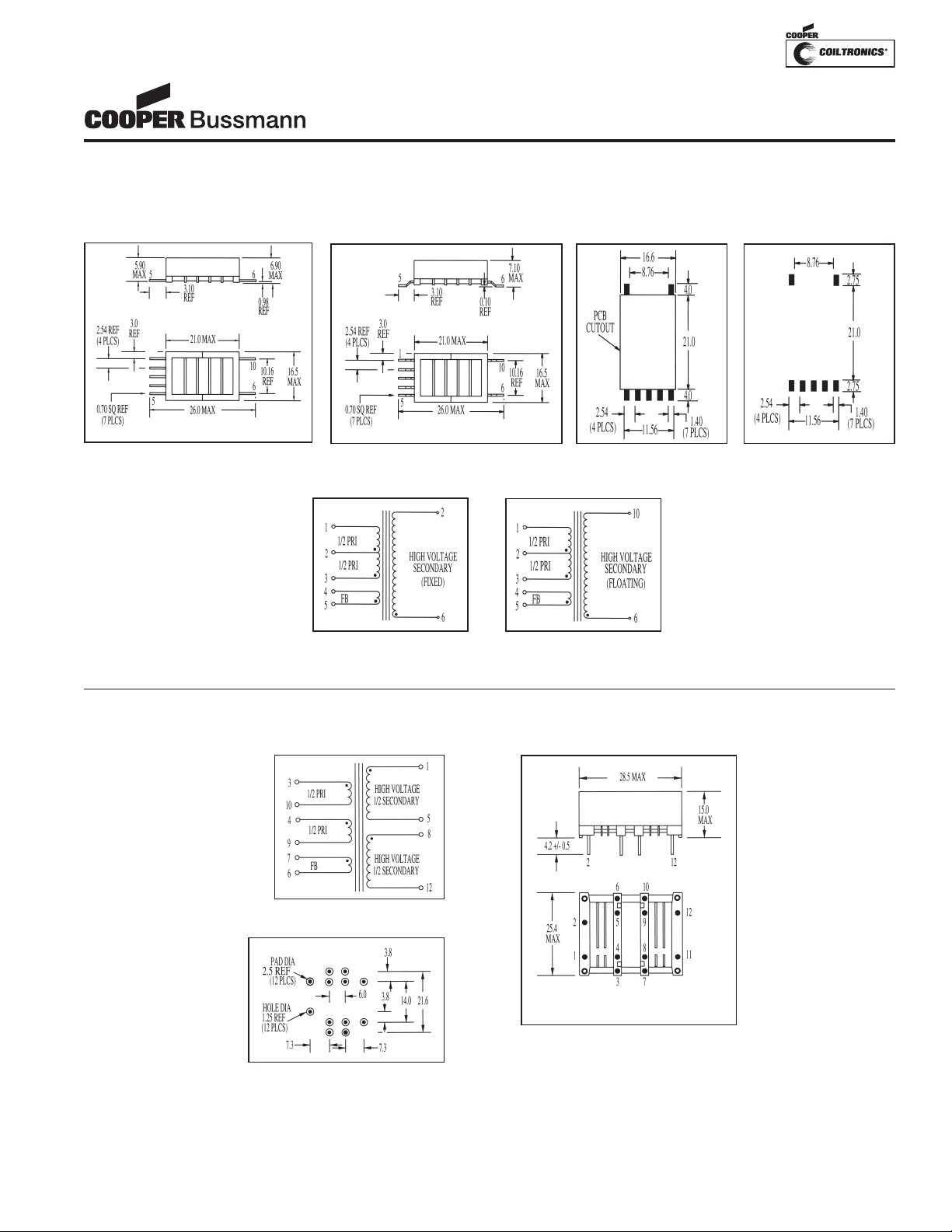
Mechanical DiagramsMechanical Diagrams
6 Watt Versions
CCFL TRANSFORMERS
Cold Cathode Fluorescent
Lamp Inverter Transformers
OP VIEW
T
Dimensions are in millimeters
Mechanical F
Schematic D
TOP VIEW
Schematic C
Pad Layout E
Pad Layout CMechanical E
14 Watt Versions
Schematic E
Pad Layout F
Mechanical G
BOTTOM VIEW
Dimensions are in millimeters
Page 4

CCFL TRANSFORMERS
Cold Cathode Fluorescent
Lamp Inverter Transformers
PM-4303 3/07
© Cooper Electronic
Technologies 2007
Visit us on the Web at www.cooperbussmann.com
1225 Broken Sound Pkwy. Suite F Boca Raton, FL 33487
Tel: +1-561-998-4100 Toll Free: +1-888-414-2645 Fax: +1-561-241-6640
This bulletin is intended to present product design solutions and technical information that will help the end user with design applications. Cooper Electronic
Technologies reser
Electronic T
selected, it should be tested by the user in all possible applications.
Life Support Policy: Cooper Electronic Technologies does not authorize the use of any of its products for use in life support devices or systems without the
express written approval of an officer of the Company. Life support systems are devices which support or sustain life, and whose failure to perform, when
properly used in accordance with instructions for use provided in the labeling, can be reasonably expected to result in significant injury to the user.
ves the right, without notice, to change design or construction of any products and to discontinue or limit distribution of any products. Cooper
echnologies also reser
ves the right to change or update, without notice, any technical information contained in this bulletin. Once a product has been
 Loading...