

Page 1

Transformer Selection
The CCFL lamp manufacturer supplies the following lamp characteristics:
1. Strike voltage (V
strike
)
2. Running voltage (V
run
)
3. Frequency of operation (F
res
)
4. Power (W)
5. Current (I
lamp
)
The first step is to select the transformer according to the power
requirement from the catalog.
The second step is to decide the termination.
Use this formula to find the turn ratio needed to obtain the strike voltage of
the lamp.
TR = Turns ratio
V
in min
= Battery voltage
Cold Cathode Fluorescent Lamps (CCFLs) are used to illuminate Liquid
Crystal Displays (LCDs). The LCD display is used in laptop computers, gas
pumps, automobiles, test equipment, PDAs and medical instruments.
CCFLs are small, efficient and inexpensive. The lamp must be driven by a
specialized power supply. High sinusoidal AC voltage is needed to start the
lamps, but once started, the voltage drops to a lower level. CCFL circuits
are usually powered from a low voltage DC source of 5-12V. The DC to AC
power supply needs a transformer to change low DC input voltage to high
sinusoidal AC voltage.
The Cooper Bussmann
®
Coiltronics®brand CCFL transformers are
designed to work with inexpensive Royer class self-oscillating circuits. The
Royer circuit works with input voltage from 2.5 to 20Vdc and is capable of
producing 90% efficiency above 5Vdc input.
Royer Diagram
A current-fed, push-pull topology is commonly used to power the CCFL
transformer. This topology accommodates a wide input voltage and
consists of a resonant push-pull stage, a Pulse-Width-Modulated (PWM)
buck-derived control stage and a high-voltage secondary stage. The pushpull stage consists of transistors Q2 and Q3 to drive the center-tapped
transformer T1. The transistors are driven 180° out of phase at 50% duty
cycle with an auxiliary winding on the transformer. A resonant tank is
formed between the primary inductance of the transformer and a lowloss, external resonant bulk capacitor C1. The resonant tank provides a
sinusoidal voltage to the transformer’s primary winding and sets the
system’s operating frequency.
The high voltage at the secondary of transformer is used to ignite and
operate the lamp. Since the ignition or “strike voltage” is higher than the
operating voltage, a high voltage ballast capacitor C2 is required to allow
a voltage difference between the transformer secondary and the lamp. To
minimize lamp stress and improve efficiency, the striking voltage
waveforms should be sinusoidal.
CCFL Transformer Application Note
V
strike
π
V
×
in
min
TR
=
×
2
Page 2

The operating frequency of the system is determined by the inductance of
the primary and the bulk capacitor across the primary at resonance.
Fres = Resonance Frequency
Determine the ballast capacitor value using the equation below.
V
sec
= Transformer secondary voltage
V
run
= Lamp running voltage
I
lamp
= Lamp current
F
res
= Resonance frequency
C
ballast
= Ballast capacitor
The capacitor voltage is 90 degrees out of phase with the lamp running
voltage.
From this equation, determine the value of the ballast capacitor.
Coiltronics®Transformer Features:
1. Supply high voltage.
2. Operation frequency range from 40 to 80kHz.
3. Deliver output power from 2.5 to 14 watts.
4. Slim or low profile type easily built into your design.
5. Available in through-hole and SMT recess or gull wing type.
6. Operate in Royer and direct IC drive.
7. 1500 volt primary to secondary isolation.
8. Ferrite core material.
9. Designed for floating and non-floating applications.
10. Transformer secondary is machine wound on sections to increase
leakage inductance and reduce voltage gradient between layers.
Layout and Circuit Considerations
•The high voltage traces must be separated from low voltage traces.
•The ballast capacitor must be placed closer to the transformer secondary
pin.
•Avoid long wire connections from the transformer to the lamp. Stray
capacitance between wire and ground will reduce efficiency.
•Incorporate open lamp and overload protection in the circuit design. Open
lamp will cause full voltage in the transformer output and will burn the
transformer. Most of the CCFL IC has protection built in the circuit for
open and overload condition.
Schematic Relation to Part Number
Schematic A Schematic B Schematic C Schematic D Schematic E
CTX110652-R CTX110655-R CTX210403-R CTX110603-R CTX110600-R CTX410805-R
CTX210652-R CTX110657-R CTX210407-R CTX110605-R CTX210600-R CTX410807-R
CTX110659-R CTX210409-R CTX110607-R CTX410809-R
CTX210655-R CTX210411-R CTX110609-R
CTX210657-R CTX310403-R CTX110611-R
CTX210659-R CTX310405-R CTX210603-R
CTX310407-R CTX210605-R
CTX310409-R CTX210607-R
CTX310411-R CTX210609-R
CTX210611-R
=
s
Re
2
C
ballast
=
π
1
I
Pr
lamp
CLF××
Bulki
2
runres
)(2
VVF
−××
sec
π
Page 3
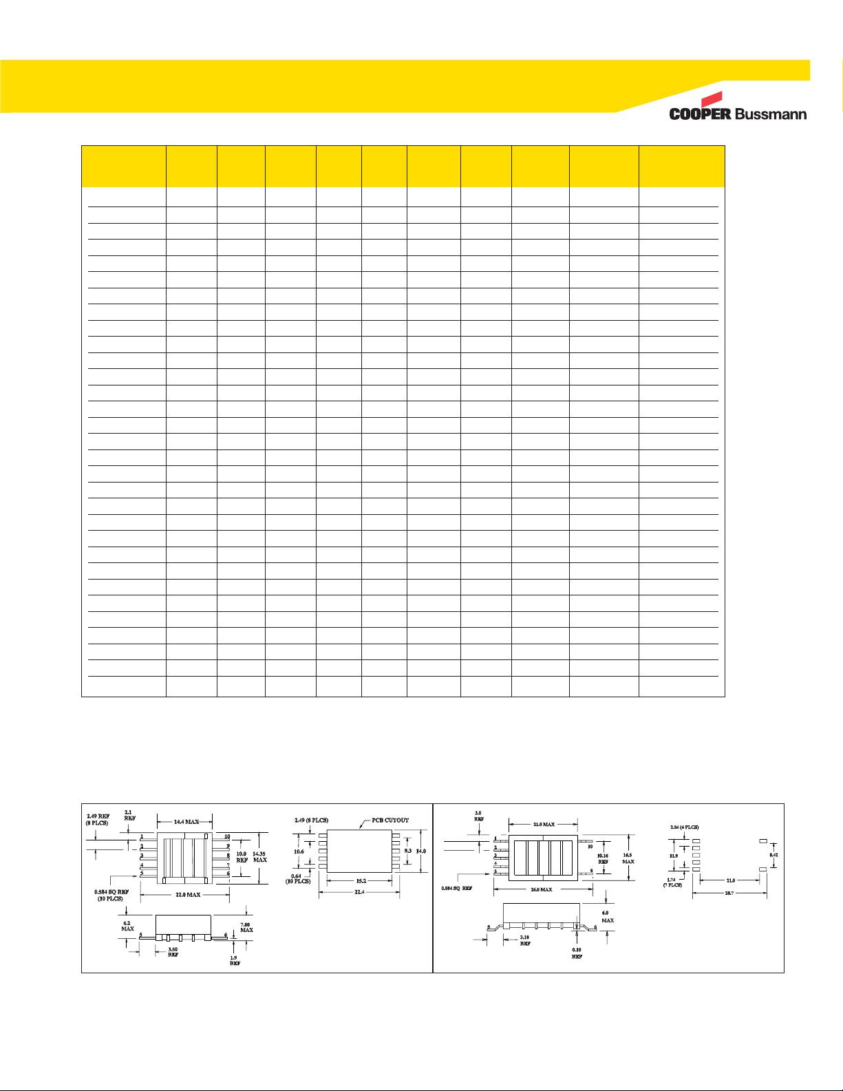
Part Power TR1 TR2 L
pri
V
pri
I
sec
DCR
pri
DCR
sec
Schematic Mechanical
Number Watts Ns/Np Np/FB μH Volts mA max Ω max Ω max Reference Reference
CTX110652-R 2.5 67 6 43 20 5 0.220 285 A A
CTX110655-R 2.5 67 6 43 20 5 0.220 285 B A
CTX110657-R 2.5 86 2 26 15 5 0.212 285 B A
CTX110659-R 2.5 100 4 19 13 5 0.190 285 B A
CTX210652-R 2.5 67 6 43 20 5 0.220 285 A C
CTX210655-R 2.5 67 6 43 20 5 0.220 285 B C
CTX210657-R 2.5 86 2 26 15 5 0.212 285 B C
CTX210659-R 2.5 100 4 19 13 5 0.190 285 B C
CTX210403-R 4.00 50 6 44 26 7 0.220 165 C B
CTX210407-R 4.00 86 4.7 27 15 7 0.160 220 C B
CTX210409-R 4.00 100 4 20 13 7 0.160 220 C B
CTX210411-R 4.00 125 4 20 10 7 0.160 330 C B
CTX310403-R 4.00 50 6 44 26 7 0.220 165 C D
CTX310407-R 4.00 86 4.7 27 15 7 0.160 220 C D
CTX310409-R 4.00 100 4 20 13 7 0.160 220 C D
CTX310411-R 4.00 125 4 20 10 7 0.160 330 C D
CTX110600-R 6.00 67 6 44 20 12 0.160 176 D E
CTX110603-R 6.00 50 6 44 26 12 0.160 132 C E
CTX110605-R 6.00 67 6 44 20 12 0.160 176 C E
CTX110607-R 6.00 86 4.7 27 15 12 0.132 176 C E
CTX110609-R 6.00 100 6 20 13 12 0.132 176 C E
CTX110611-R 6.00 125 4 20 13 12 0.132 291 C E
CTX210600-R 6.00 67 6 44 20 12 0.160 176 D F
CTX210603-R 6.00 50 6 44 26 12 0.160 132 C F
CTX210605-R 6.00 67 6 44 20 12 0.160 176 C F
CTX210607-R 6.00 86 4.7 27 15 12 0.132 176 C F
CTX210609-R 6.00 100 6 20 13 12 0.132 176 C F
CTX210611-R 6.00 125 4 20 13 12 0.132 291 C F
CTX410805-R 14.00 67 5 24 30 30 0.030 262 F G
CTX410807-R 14.00 86 4 16 23 30 0.024 272 F G
CTX410809-R 14.00 100 4 16 23 30 0.024 314 F G
Full primary turns used in turns ratio calculation.
Ns/Np= Turns Secondary/Turns Primary.
Np/FB= Turns Primary/FeedBack Winding.
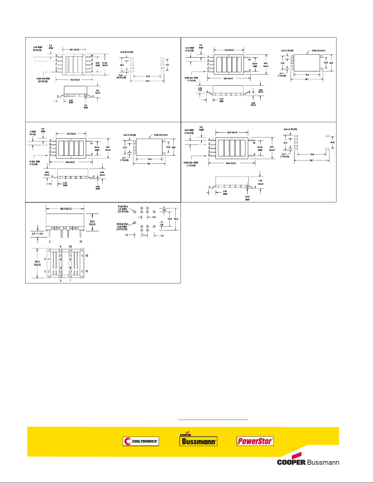
Mechanical References
A
B
Page 4
© 2008 Cooper Bussmann
St. Louis, MO 63178
636-394-2877
www.cooperbussmann.com
Reorder # 4035 PDF Only
Order samples online - www.cooperbussmann.com
The Cooper Bussmann®Coiltronics®brand of magnetics specializes in standard and custom solutions, offering the latest in state-of-the-art low-profile
high power density magnetic components. We remain at the forefront of innovation and new technology to deliver the optimal mix of packaging, high
efficiency and unbeatable reliability. Our designs utilize high frequency, low core loss materials, and new and custom core shapes in combination with
innovative construction and packaging to provide designers with the highest performance parts available on the market. The Coiltronics Brand product line
of power magnetics continually expands to satisfy shifts in technology and related market needs. Standard Product Categories include:
• Shielded Drum Inductors • Unshielded Drum Inductors • High Current Inductors
• Toroidal Inductors • Specialty Magnetics • Custom Magnetics
Please visit http://www.cooperbussmann.com/datasheets/elx to see the wide variety of inductor solutions we have to offer.
Mechanical References
DC
EF
G
 Loading...