

Page 1
CN-0221
Rev. 0
Circuits from the Lab™ circuits from Analog Devices have been designed and built by Analog Devices
each circuit, and their function and performance have been tested and verified in a lab environment at
room temperature. However, you are solely responsible for testing the circuit and determining its
r your use and application. Accordingly, in no event shall Analog Devices
be liable for direct, indirect, special, incidental, consequential or punitive damages due to any cause
whatsoever connected to the use of any Circuits from the Lab circuits. (Continued on last page)
Fax: 781.461.3113 ©2012 Analog Devices, Inc. All rights reserved.
ADuCM360
AIN5/IEXC
AVDD IOVDD
AIN0
RxD
RxD
TxD
TxD
RESET
P2.2/BM
RESET
SD
V
REF
+
R
REF
V
REF
–
AIN1
5.6k
Ω
0.1%
100
Ω
PtRTD
AIN2
THERMOCOUPLE
JUNCTION
AIN3
J1
AIN7/VBIAS
AGND
09985-001
BEAD
3.3V
BEAD
USB HEADER
10Ω
10Ω
10Ω
0.01µF
0.01µF
0.1µF
4.7µF
4.7µF
0.1µF
10µF
IN
5V
D–
D+
GND
OUT
GND
ADP1720-3.3
FT232R
BEAD
FERRITE BE ADS :
1kΩ @ 100MHz
TAIYO Y UDE N
BK2125HS102-T
0.1µF
SHIELD
P0.2/SOUT
P0.1/SIN
Circuits from the Lab™ reference circuits are engineered and
tested for quick and easy system integration to help solve today’s
analog, mixed-signal, and RF design challenges. For more
information and/or support, visit www.analog.com/CN0221.
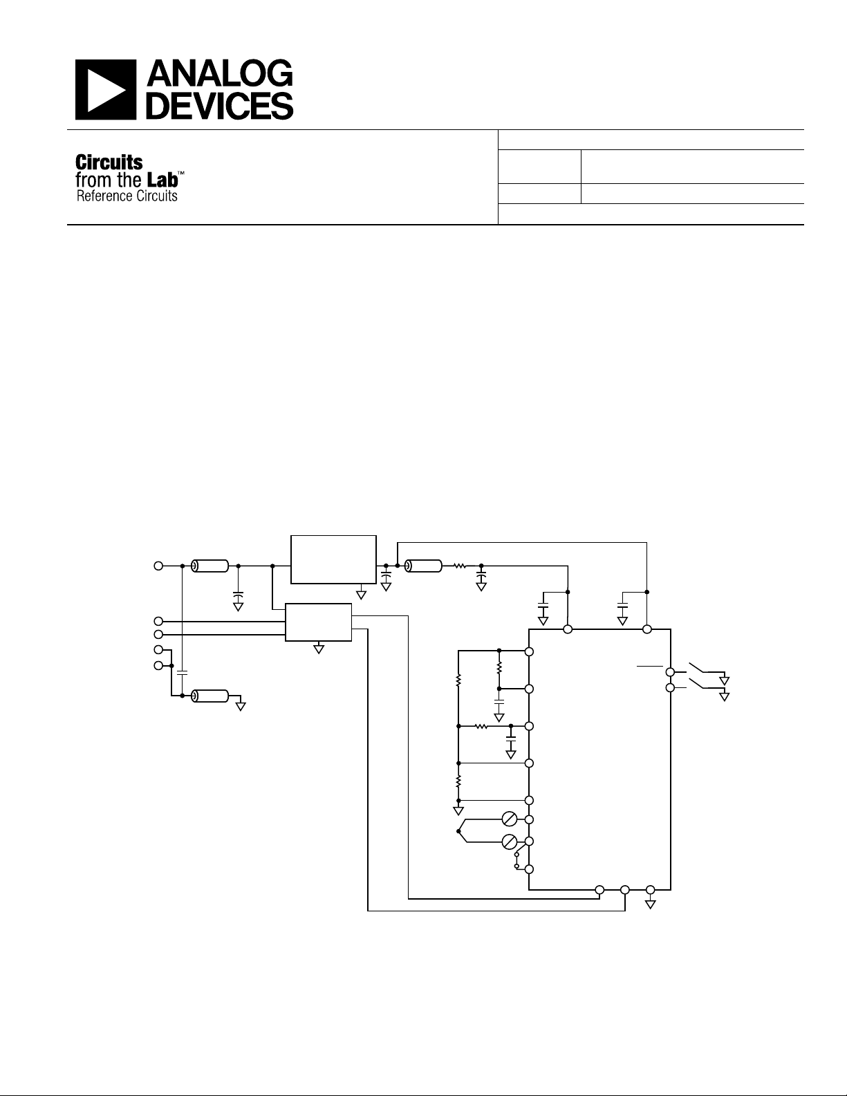
USB-Based Temperature Monitor Using the ADuCM360 Precision Analog
Microcontroller and an External Thermocouple
EVALUATION AND DESIGN SUPPORT
Circuit Evaluation Board
CN-0221 Evaluation Board (EVAL-ADuCM360TCZ)
Design and Integration Files
Schematics, Layout Files, Bill of Materials, source code for
ADuCM360
CIRCUIT FUNCTION AND BENEFITS
This circuit uses the ADuCM360/ADuCM361 precision analog
microcontroller in an accurate thermocouple temperature
monitoring application. The ADuCM360/ADuCM361 integrates
dual 24-bit sigma-delta (Σ-Δ) analog-to-digital converters (ADCs),
dual programmable current sources, a 12-bit digital-to-analog
Circuit Note
Devices Connected/Referenced
ADuCM360/
ADuCM361
ADP1720-3.3 Low Dropout Linear Regulator
converter (DAC), and a 1.2 V internal reference, as well as an ARM
Cortex-M3 core, 126 kB flash, 8 kB SRAM, and various digital
peripherals such as UART, timers, SPIs, and I
In the circuit, the ADuCM360/ADuCM361 is connected to a
thermocouple and a 100 Ω platinum resistance temperature
detector (RTD). The RTD is used for cold junction compensation.
In the source code, an ADC sampling rate of 4 Hz is chosen. When
the ADC input programmable gain amplifier (PGA) is configured
for a gain of 32, the noise-free code resolution of the ADuCM360/
ADuCM361 is greater than 18 bits.
Cortex-M3 Based Microcontroller with
Dual 24-Bit Σ-Δ ADCs
2
C interfaces.
Figure 1. ADuCM360/ADuCM361 as a Temperature Monitor Controller with a Thermocouple Interface (Simplified Schematic, All Connections Not Shown)
engineers. Standard engineering practices have been employed in the design and construction of
suitability and applicability fo
One Technology Way, P.O. Box 9106, Norwood, MA 02062-9106, U.S.A.
Tel: 781.329.4700
www.analog.com
Page 2
CN-0221 Circuit Note
09985-002
CIRCUIT DESCRIPTION
The following features of the ADuCM360/ADuCM361 are used
in this application:
• A 24-bit Σ-Δ ADC with a PGA set for a gain of 32 in the
software for the thermocouple and RTD. The ADC1 was
switched continuously between sampling the thermocouple
and the RTD voltages.
• Programmable excitation current sources for forcing a
controlled current through the RTD. The dual current
sources are configurable in from 0 µA to 2 mA. For this
example, a 200 µA setting was used to minimize the error
introduced by the RTD self-heating.
• An internal 1.2 V reference for the ADC in the ADuCM360/
ADuCM361. It measures the thermocouple voltage; the
internal voltage reference was used due to its precision.
• An external voltage reference for the ADC in the
ADuCM360/ADuCM361. It measures the RTD resistance;
a ratiometric setup was used where an external reference
resistor (R
and VREF− pins.
• A bias voltage generator (VBIAS). The VBIAS function was
used to set the thermocouple common-mode voltage to
AVDD/2.
• The ARM Cortex-M3 core. The powerful 32-bit ARM core
with integrated 126 kB flash and 8 kB SRAM memory runs
the user code that configures and controls the ADC, processes
the ADC conversions from the RTD, and controls the
communications over the UART/USB interface.
• The UART was used as the communication interface to the
host PC.
• Two external switches are used to force the part into its
flash boot mode. By holding SD low and toggling the RESET
button, the ADuCM360/ADuCM361 enters boot mode
instead of normal user mode. In boot mode, the internal
flash can be reprogrammed through the UART interface.
Both the thermocouple and the RTD generate very small signals;
therefore, a PGA is required to amplify those signals.
The thermocouple used in this application is a Type T (copperconstantan) that has a temperature range of −200°C to +350°C.
Its sensitivity is approximately 40 µV/°C, which means that the
ADC in bipolar mode, with a PGA gain of 32, can cover the
entire temperature range of the thermocouple.
The RTD was used for cold junction compensation. The
particular one used in this circuit was a platinum 100 Ω RTD,
Enercorp PCS 1.1503.1. It is available in a 0805, surface-mount
package. This RTD has a temperature variation of 0.385 Ω/°C.
) was connected across the external VREF+
REF
Note that the reference resistor, R
5.6 kΩ (±0.1%).
The USB interface to the ADuCM360/ADuCM361 is implemented
with an FT232R UART to USB transceiver, which converts USB
signals directly to the UART.
In addition to the decoupling shown Figure 1, the USB cable itself
must have a ferrite bead for added EMI/RFI protection. The ferrite
beads used in the circuit were Taiyo Yuden, #BK2125HS102-T,
which have an impedance of 1000 Ω at 100 MHz.
Construct the circuit on a multilayer printed circuit board (PCB)
with a large area ground plane. Use proper layout, grounding,
and decoupling techniques to achieve optimum performance (see
Tutorial MT-031, Grounding Data Converters and Solving the
Mystery of "AGND" and "DGND," Tut o r ia l MT-101, Decoupling
Techni q u e s , and the ADuCM360TCZ Evaluation Board layout).
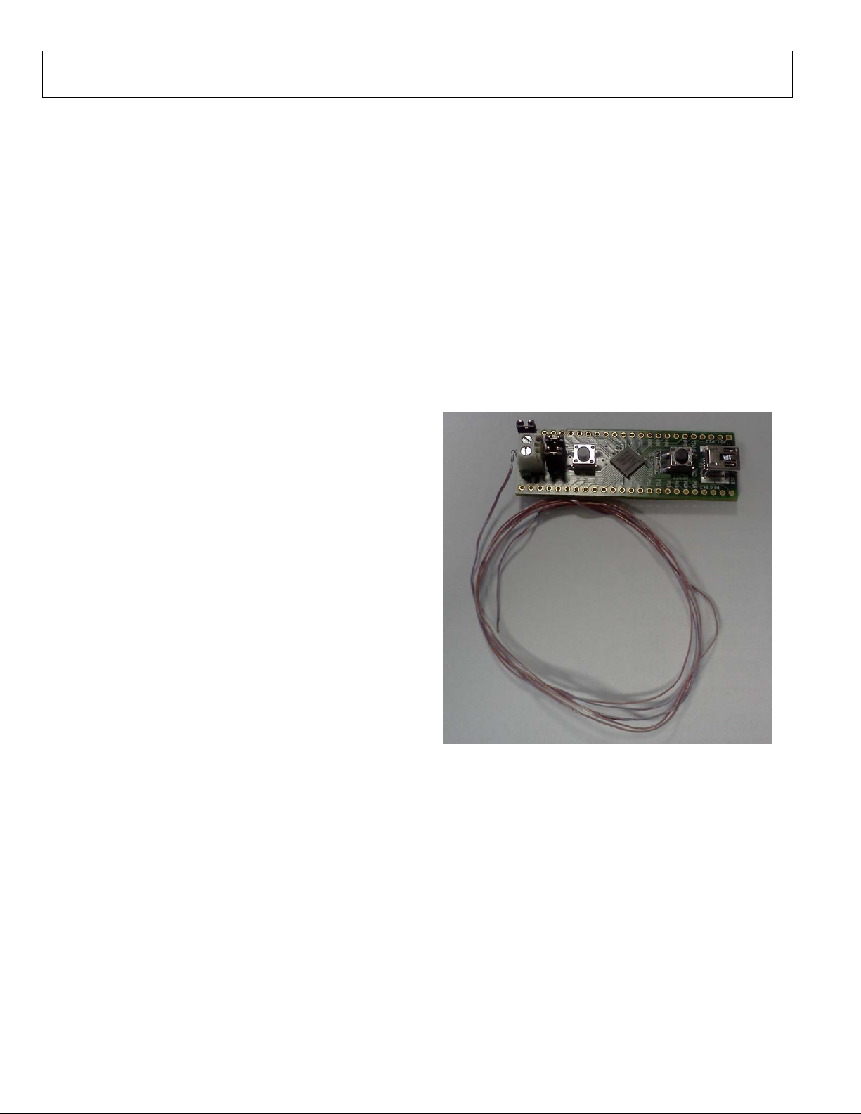
The PCB used for evaluating this circuit is shown in Figure 2.
Figure 2. EVAL-ADuCM360TCZ Board Used for this Circuit
, should be a precision
REF
Rev. 0 | Page 2 of 5
Page 3

Circuit Note CN-0221
09985-003
20
0
–20
–40
–60
–80
–100
–210 –140 –70 0 70 140 210 280 350
ERROR (°C)
TEMPERATURE (°C)
09985-004
0.30
0.25
0.20
0
0.05
0.10
0.15
–0.05
–210 –140 –70 0 70 140 210 280 350
ERROR (°C)
TEMPERATURE (°C)
09985-005
Code Description
The source code used to test the circuit can be downloaded as a zip
file from the ADuCM360 product page.
The UART is configured for a baud rate of 9600, 8 data bits, no
pari t y, and no flow control. If the circuit is connected directly to
a PC, a communication port viewing application, such as a
HyperTerminal, can be used to view the results sent by the
program to the UART, as shown in Figure 3.
Figure 4. Error When Using Simple Linear Approximation
Initially, this was done using a simple linear assumption that the
voltage on the thermocouple was 40 µV/°C. It can be seen from
Figure 4 that this gives an acceptable error only for a small range,
around 0°C. A better way of calculating the thermocouple
temperatures is to use a six-order polynomial for the positive
temperatures and a seventh-order polynomial for the negative
temperatures. This requires mathematical operations that add
to computational time and code size. A suitable compromise is to
calculate the respective temperatures for a fixed number of
voltages. These temperatures are stored in an array, and values in
between are calculated using a linear interpolation between the
adjacent points. It can be seen from Figure 5 that the error is
drastically reduced using this method. Figure 5 gives the algorithm
error using ideal thermocouple voltages.
Figure 3. Output of HyperTerminal Communication Port Viewing Application
To get a temperature reading, measure the temperature of the
thermocouple and the RTD. The RTD temperature is converted
to its equivalent thermocouple voltage via a look-up table (see the
ISE, Inc., ITS-90 Table for Type T Thermocouple). These two
voltages are added together to give the absolute value at the
thermocouple.
First, the voltage measured between the two wires of the
thermocouple (V1). The RTD voltage is measured, converted to
a temperature via a look-up table, and then, this temperature is
converted to its equivalent thermocouple voltage (V2). V1 and
V2 are then added to give the overall thermocouple voltage, and
this is then converted to the final temperature measurement.
Figure 5. Error When Using Piecewise Linear Approximation Using
Rev. 0 | Page 3 of 5
52 Calibration Points and Ideal Measurements
Page 4

CN-0221 Circuit Note
–0.5
–0.4
–0.3
–0.2
–0.1
0
0.1
0.2
0.3
0.4
0.5
–210 –140 –70 0 70 140 210 280 350
ERROR (°C)
TEMPERATURE (°C)
09985-006
EVAL-ADuCM360TCZ
WAVETEK 4808
MULTIFUNCTION
CALIBRATOR
PC
J5
J1
AIN7/VBIAS
THERMOCOUPLE
JUNCTION
SEE TEXT
USB
CABLE
09985-007
Figure 6 shows the error obtained when using ADC1 on the
ADuCM360 to measure 52 thermocouple voltages over the full
thermocouple operating range. The overall worst-case error
is <1°C.
Figure 6. Error When Using Piecewis e Linear Approximation Using
52 Calibration Points Measured by ADuCM360/ADuCM361
The RTD temperature is calculated using lookup tables and is
implemented for the RTD the same way as for the thermocouple.
Note that the RTD has a different polynomial describing its
temperatures as a function of resistance.
For details on linearization and maximizing the performance of
the RTD, refer to Application Note AN-0970, RTD Interfacing
and Linearization Using an ADuC706x Microcontroller.
COMMON VARIATIONS
The ADP1720 regulator can be replaced with the ADP120, which
has the same operating temperature range (−40°C to +125°C)
and consumes less power (typically 35 µA vs. 70 µA) but has a
lower maximum input voltage. Note that the ADuCM360/
ADuCM361 can be programmed or debugged via a standard
serial wire interface.
For a standard UART to RS-232 interface, the FT232R transceiver
can be replaced with a device such as the ADM3202, which
requires a 3 V power supply. For a wider temperature range, a
different thermocouple can be used, such as a Type J. To minimize
the cold junction compensation error, a thermistor can be placed in
contact with the actual cold junction instead of on the PCB.
Instead of using the RTD and external reference resistor for
measuring the cold junction temperature, an external digital
temperature sensor can be used. For example, the ADT7410 can
connect to the ADuCM360/ADuCM361 via the I
For more details on cold junction compensation, refer to Sensor
Signal Conditioning, Analog Devices, Chapter 7, “Temperature
Sensors.”
If isolation between the USB connector and this circuit is required,
the ADuM3160/ADuM4160 isolation devices must be added.
2
C interface.
CIRCUIT EVALUATION AND TEST
To test and evaluate the circuit, the thermocouple measurements
and the RTD measurements were evaluated separately.
Thermocouple Measurement Test
The basic test setup is shown in Figure 7. The thermocouple is
connected to J5, and Jumper J1 must be installed to allow the
AIN7/VBIAS pin to set the thermocouple common-mode
voltage. The circuit board receives its power from the USB
connection to the PC.
Two methods were used to evaluate the performance of the
circuit. Initially, the circuit was tested with the thermocouple
attached to the board and it was used to measure the temperature
of an ice bucket. Then, it was used to measure the temperature
of boiling water.
A Wavetek 4808 Multifunction Calibrator was used to fully
evaluate the error, as shown in Figure 4 and Figure 6. In this
Rev. 0 | Page 4 of 5
mode, the thermocouple was replaced with the calibrator as the
voltage source, as shown in Figure 7. To evaluate the entire range
of a Type T thermocouple, the calibrator was used to set the
equivalent thermocouple voltage at 52 points between −200°C
to +350°C for the negative and positive ranges of the T-type
thermocouple (see the ISE, Inc., ITS-90 Table for Type T
Thermocouple).
To evaluate the accuracy of the lookup algorithm, 551 voltage
r
+350°C spaced at +1°C, were passed onto the temperature
calculation functions. Errors were calculated for the linear
method and the piecewise linear approximation method as is
shown in Figure 4
eadings, equivalent to temperatures in the range of −200°C to
and Figure 5.
Figure 7. Test Setup Used to Calibrate and Test the Circuit Over Full
Thermocouple Output Voltage Range
Page 5

Circuit Note CN-0221
1433-Z
DECADE
RESISTOR
ADuCM360
0.1µF
0.01µF
0.01µF
R
REF
5.6kΩ
0.1%
10Ω
10Ω
AVDD
V
REF
+
V
REF
–
IOVDD
AVDD IOVDD
0.1µF
09985-008
AIN5/IEXC
AIN0
AIN1
0
–0.01
–25 –5
ERROR (°C)
TEMPERATURE (°C)
–0.02
–0.03
–0.04
–0.05
–0.06
–0.07
–0.08
–0.09
–0.10
15 35 55 75 95 115
09985-009
(Continued from f irst page) Circuits from the Lab circuits are intended only for use with Analog Devices products and are the intellectual property of Analog Devices or its licensors. While you
reserves the right to change any Circuits from the Lab circuits at any time without notic e but is under no obligation to do so.
registered trademarks are the property of their respective owners.
RTD Measurement Test
To evaluate the RTD circuit and linearization source code, the
RTD on the board was replacement with an accurate, adjustable
resistance source. The instrument used was the 1433-Z Decade
Resistor. The RTD values are from 90 Ω to 140 Ω, which represents
an RTD temperature range of −25°C to +114°C.
The test setup circuit is shown in Figure 8, and the error results
for the RTD tests are shown in Figure 9.
LEARN MORE
CN0221 Design Support Package:
http://www.analog.com/CN0221-DesignSupport
ADIsimPower Design Tool.
Kester, Walt. 1999. Sensor Signal Conditioning. Analog Devices.
Chapter 7, "Temperature Sensors."
Kester, Wa lt. 1999. Sensor Signal Conditioning. Analog Devices.
Chapter 8, "ADCs for Signal Conditioning."
Looney, Mike. RTD Interfacing and Linearization Using an
ADuC706x Microcontroller. AN-0970 Application Note.
Analog Devices.
MT-022 Tutorial, ADC Architectures III: Sigma-Delta ADC
Basics. Analog Devices.
MT-023 Tutorial, ADC Architectures IV: Sigma-Delta ADC
Advanced Concepts and Applications. Analog Devices.
MT-031 Tutorial, Grounding Data Converters and Solving the
Mystery of "AGND" and "DGND." Analog Devices.
MT-101 Tutorial, Decoupling Techniques. Analog Devices.
ITS-90 Table for Type T Thermocouple.
Figure 8. Test Setup for Measuring RTD Error
Data Sheets and Evaluation Boards
ADuCM360/ADuCM361 Data Sheet
ADuCM360/ADuCM361 Evaluation Kit
ADM3202 UART to RS232 Transceiver Data Sheet
ADP120 Data Sheet
ADP1720 Data Sheet
REVISION HISTORY
5/12—Revision 0: Initial Version
Figure 9. Error in °C of RTD Measurement Using Piecewise Linearization Code
and ADC0 Measurements
may use the Circuits from the Lab circuits in the design of your product, no other license is granted by implication or otherwise under any patents or other intellectual property by
application or use of the Circuits from the Lab circuits. Information furnished by Analog Devices is believed to be accurate and reliable. However, Circuits from the Lab circuits are supplied
"as is" and without warranties of any kind, express, implied, or statutory including, but not limited to, any implied warranty of merchantability, noninfringement or fitness for a particular
purpose and no responsibility is assumed by Analog Devices for their use, nor for any infringements of patents or other rights of third parties that may result from their use. Analog Devices
©2012 Analog Devices, Inc. All rights reserved. Trademarks and
CN09985-0-5/12(0)
Rev. 0 | Page 5 of 5
 Loading...