

Page 1
DATA BULLETIN
CMX469A
1999 MX-COM, Inc. www.mxcom.com tel: 800 638 5577 336 744 5050 fax: 336 744 5054 Doc. # 20480191.002
4800 Bethania Station Road, Winston-Salem, NC 27105-1201 USA All trademarks and service marks are held by their respective companies.
1200/2400/4800bps
MSK Modem
PRELIMINARY INFORMATION
Features Applications
•
Selectable Data Rates
1200/2400/4800 bps
•
Full-Duplex MSK
•
RX and TX Bandpass Filters
•
Clock Recovery and Carrier Detect
Capabilities
•
Pin Selected Xtal/Clock Inputs
1.008MHz or 4.032MHz
•
Radio and General Applications
•
Data-Over-Radio
•
PMR/Cellular Signaling
•
Portable Data Terminals
•
Narrowband Coax Data Channels
•
Two Way Radio (MPT1327) Signaling
•
Personal/Cordless Telephone
The CMX469A is a full-duplex pin-selectable 1200/2400/4800bps Minimum Shift Key (MSK) Modem for FM
radio links. The mark and space frequencies are 1200/1800, 1200/2400, and 2400/4800Hz respectively.
Tone frequencies are phase continuous; transitions occur at the zero crossing point. The use of a common
Xtal oscillator with a choice of two clock frequencies (1.008MHz or 4.032MHz) provides data-rate, transmit
frequencies, and RX/TX synchronization. The transmitter and receiver operate entirely independently
including individual section powersave functions.
The CMX469A includes on-chip circuitry for Carrier Detect and RX Clock Recovery, both of which are made
available at output pins. RX, TX and Carrier Detect circuits contain bandpass filters to provide high quality
signals to their respective paths. The carrier detect time constant is set by an external capacitor, which may
be selected to optimize performance in high-noise environments.
High sensitivity and good bit-error-rate performance can be achieved even under adverse signal conditions.
The CMX469A operates with a 3.0V to 5.5V supply and is available in the following packages:
24-pin TSSOP (CMX469AE2), 20-pin SOIC (CMX469AD3), and 22-pin PDIP (CMX469AP6).
Page 2

1200/2400/4800bps MSK Modem 2 CMX469A PRELIMINARY INFORMATION
1999 MX-COM, Inc. www.mxcom.com tel: 800 638 5577 336 744 5050 fax: 336 744 5054 Doc. # 20480191.002
4800 Bethania Station Road, Winston-Salem, NC 27105-1201 USA All trademarks and service marks are held by their respective companies.
Contents
Section Page
1. Block Diagram................................................................................................................3
2. Signal List.......................................................................................................................4
3. External Components....................................................................................................6
4. General Description.......................................................................................................7
4.1 Transmitter .......................................................................................................................... 7
4.2 Receiver .............................................................................................................................. 7
5. Application .....................................................................................................................8
5.1 Synchronous Modem Design Considerations ..................................................................... 8
5.2 Test Set Up.......................................................................................................................... 9
5.3 Bit Error Rate....................................................................................................................... 9
6. Performance Specifications........................................................................................11
6.1 Electrical Specifications..................................................................................................... 11
6.1.1 Absolute Maximum Limits.........................................................................................................11
6.1.2 Operating Limits .......................................................................................................................11
6.1.3 Operating Characteristics.........................................................................................................12
6.1.4 Timing.......................................................................................................................................14
6.2 Packages........................................................................................................................... 17
MX-COM, Inc. reserves the right to change specifications at any time without notice.
Page 3
1200/2400/4800bps MSK Modem 3 CMX469A PRELIMINARY INFORMATION
1999 MX-COM, Inc. www.mxcom.com tel: 800 638 5577 336 744 5050 fax: 336 744 5054 Doc. # 20480191.002
4800 Bethania Station Road, Winston-Salem, NC 27105-1201 USA All trademarks and service marks are held by their respective companies.
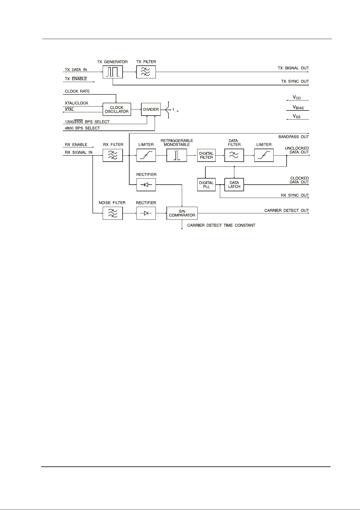
1. Block Diagram
Figure 1: Block Diagram
Page 4

1200/2400/4800bps MSK Modem 4 CMX469A PRELIMINARY INFORMATION
1999 MX-COM, Inc. www.mxcom.com tel: 800 638 5577 336 744 5050 fax: 336 744 5054 Doc. # 20480191.002
4800 Bethania Station Road, Winston-Salem, NC 27105-1201 USA All trademarks and service marks are held by their respective companies.
2. Signal List
Pin No. Signal
E2 P6 D3 Name Type
Description
1 1 1 Xtal/Clock input
The input to the on-chip inverter, for use with either a
1.008MHz or a 4.032MHz Xtal or external clock.
Clock frequency selection is by the “Clock Rate”
input pin. The selection of this frequency will affect
the operational Data Rate of this device. Refer to
Table 3.
As specified in the Performance Specifications, this
input signal should be actively clocked (either driven
from an external source or via an XTAL circuit).
222
XTAL
output Output of the on-chip inverter.
3 3 3 TX Sync Out output
A squarewave, produced on-chip, to synchronize the
input of logic data and transmission of the MSK
signal. See Figure 8 and Section 4.1.
5 5 4 TX Signal Out output
When the transmitter is enabled, this pin outputs the
(140-step pseudo sinewave) MSK signal. See
Figure 8. With the transmitter disabled, this output is
set to a high-impedance state.
7 6 5 TX Data In input Serial logic data to be transmitted is input to this pin.
876
ENABLE TX
input
A logic ‘0’ will enable the transmitter. See Figure 8.
A logic ‘1’ at this input will put the transmitter into
powersave while forcing “TX Sync Out” to a logic ‘1’
and “TX Signal Out” to a high-impedance state. This
pin is internally pulled to V
DD
.
9 8 7 Bandpass Out output
The output of the RX Bandpass Filter. This output
impedance is typically 10kΩ and may require
buffering prior to use.
10 9 8 RX Enable input
The control of the RX function. The control of other
outputs is provided in Table 2
11 10 9
V
BIAS
power
The output of the on-chip analog bias circuitry. Held
internally at V
DD
/2, this pin should be bypassed to
V
SS
by a capacitor (C2). See Figure 2 and RX
Enable notes. This bias voltage is maintained under
all powersave conditions.
12 11 10 V
SS
power Negative supply (GND).
13 12 11
Unclocked
Data Out
output
The recovered asynchronous serial data output from
the receiver.
14 13 12
Clocked
Data Out
output
The recovered synchronous serial data output from
the receiver. Data is latched out by the recovered
clock, available at the “RX Sync Out”. See Figure 9
and Figure 11.
15 14 13 Carrier Detect output
When an MSK signal is being received this output is
a logic ‘1’.
16 15 14 RX Signal In input
The MSK signal input for the receiver. This input
should be coupled via a capacitor, C3.
18 17 15 RX Sync Out output
A flywheel squarewave output. This clock will
synchronize to incoming RX MSK data.
See Figure 9 and Figure 11.
Page 5
1200/2400/4800bps MSK Modem 5 CMX469A PRELIMINARY INFORMATION
1999 MX-COM, Inc. www.mxcom.com tel: 800 638 5577 336 744 5050 fax: 336 744 5054 Doc. # 20480191.002
4800 Bethania Station Road, Winston-Salem, NC 27105-1201 USA All trademarks and service marks are held by their respective companies.
Pin No. Signal
E2 P6 D3 Name Type
Description
19 16 16
2400/1200
BPS Select
input
A logic ‘1’ on this pin selects the 1200bps option.
Tone frequencies are: one cycle of 1200Hz
represents a logic ‘1’, one-and-a-half cycles of
1800Hz represents a logic ‘0’.
A logic ‘0’ on this pin selects the 2400bps option.
Tone frequencies are: one-half cycle of 1200Hz
represents a logic ‘1’, one cycle of 2400Hz
represents a logic ‘0’. This pin has an internal 1M
Ω
pull-up resistor. Operational Data Rate
Configurations are illustrated in Table 3.
20 18 17
4800
BPS Select
input
A logic '1' on this pin combined with a logic '0' on the
2400/1200 BPS Select pin will select the 4800
option (1MΩ pulldown resistor). Tone frequencies
are: one-half cycle of 2400Hz represents a logic '1',
one full cycle of 4800Hz represents a logic '0'. This
state can only be achieved using a 4.032MHz Xtal
input. Operational Data Rate Configurations are
illustrated in Table 3.
21 19 18 Clock Rate input
A logic input to select and allow the use of either a
1.008MHz or 4.032MHz Xtal/clock. Logic ‘1’ =
4.032MHz, logic ‘0’ = 1.008MHz. This input has an
internal pulldown resistor (1.008MHz).
22 20 19
Carrier Detect
Time Constant
bi-directional
Part of the carrier detect integration function. The
value of C4 connected to this pin will affect the
carrier detect response time and therefore the noise
performance.
24 22 20 V
DD
power Positive supply. A single 2.7 to 5.0 volt supply is
required. This pin should be bypassed to V
SS
by a
capacitor (C5).
4, 6,
17, 23
4, 21 No internal connection, do not use.
Table 1: Signal List
RX Enable = RX Function Clock Data Output Carrier Detect Rx Sync Out
1 = Enabled Enabled * Enabled Enabled
0 = Powersave 0 1 or 0 1 or 0
* After enabling the receiver, a time of at least 8 bit periods, plus 2ms, should be allowed for
the Carrier Detect circuit to stabilize and provide a valid output.
Table 2: RX Enable Control Functions
XTAL/CLOCK Frequency 1.008MHz 4.032MHz
Clock Rate pin 00111
2400/1200 Select Pin
10100
4800 Select Pin 00001
Data Rate (bps) 1200 2400 1200 2400 4800
Table 3: Operational Data Rate Configuration
Page 6
1200/2400/4800bps MSK Modem 6 CMX469A PRELIMINARY INFORMATION
1999 MX-COM, Inc. www.mxcom.com tel: 800 638 5577 336 744 5050 fax: 336 744 5054 Doc. # 20480191.002
4800 Bethania Station Road, Winston-Salem, NC 27105-1201 USA All trademarks and service marks are held by their respective companies.
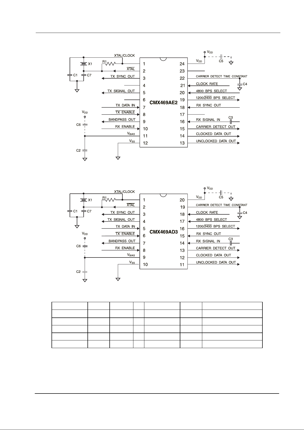
3. External Components
Figure 2: Recommended External Components for E2 package
Figure 3: Recommended External Components for D3 package
Component Notes Value Component Notes Value
R1
1.0M
Ω
C5 1.0µF
C1 33.0pF C6 1 1.0µF
C2 1 1.0µF C7 33.0pF
C3 0.1µF X1 3, 4, 5 1.008MHz or 4.032MHz
C4 2 0.1µF
Table 4: Recommended External Components
Page 7

1200/2400/4800bps MSK Modem 7 CMX469A PRELIMINARY INFORMATION
1999 MX-COM, Inc. www.mxcom.com tel: 800 638 5577 336 744 5050 fax: 336 744 5054 Doc. # 20480191.002
4800 Bethania Station Road, Winston-Salem, NC 27105-1201 USA All trademarks and service marks are held by their respective companies.
Recommended External Component Notes:
1. V
BIAS
may be bypassed to VSS and VDD using C2 and C6 when input signals are referenced to the
V
BIAS
pin. For input signals references to VSS, bypass V
BIAS
to VSS using C2 only.
2. The performance of the Carrier Detect function will be affected by the nature of the noise spectrum in
the received channel. The value of C4 determines the Carrier Detect time constant. A long time
constant results in improved noise immunity but increased response time. C4 may be varied to tradeoff response time for noise immunity.
3. A 4.032MHz Xtal/Clock is required for 4800 baud operation.
4. For best results, a crystal oscillator design should drive the clock inverter input with signal levels of at
least 40% of V
DD
, peak to peak. Tuning fork crystals generally cannot meet this requirement. To
obtain crystal oscillator design assistance, consult your crystal manufacturer.
4. General Description
The CMX469A has two sections, apart from the Xtal oscillator circuit and clock dividers. These sections may
be independently powersaved.
4.1 Transmitter
The transmitter is enabled by taking EnableTx low. Serial data applied to Tx Data Input is sampled internally
and an MSK sequence is generated. After filtering, this is output at Tx Signal Out and the transmit clock
derived from this signal is output at Tx Sync Out.
The Tx Data must be valid at the time of the rising edge of the Tx Sync clock signal. Therefore, the optimum
time to change Tx Data is on the falling edge of the Tx Sync clock.
4.2 Receiver
The receiver is enabled by taking Rx Enable high. The signal applied to Rx Signal In is filtered and recovered
as serial data from the Unclocked Data Out. A flywheel synchronizer is used to extract a clock from the
recovered serial data stream. The clock is available at Rx Sync Out and the retimed serial data is available at
Clocked Data Out. The optimum time to sample the Clocked Data Out is on the falling edge of the Rx Sync
Out clock signal.
The integrated peak values of the Rx Amplitude are compared with out-of-band noise levels and used to
make a signal-to-noise assessment, which is available at Carrier Detect Out.
A Bandpass output is also available from the output of the first Rx filter stage, but will require buffering before
use.
Page 8

1200/2400/4800bps MSK Modem 8 CMX469A PRELIMINARY INFORMATION
1999 MX-COM, Inc. www.mxcom.com tel: 800 638 5577 336 744 5050 fax: 336 744 5054 Doc. # 20480191.002
4800 Bethania Station Road, Winston-Salem, NC 27105-1201 USA All trademarks and service marks are held by their respective companies.
5. Application
5.1 Synchronous Modem Design Considerations
The CMX469A is an easily applied data pump, which can be used with many protocols. Because it is an
MSK, or minimum shift keying, modem, it achieves a more noise resistant, higher data rate in a narrower
bandwidth than other FSK (frequency shift keying) modems. This characteristic is especially important for
wireless applications because it fundamentally determines the bandwidth of RF transmissions which are
strictly limited and controlled by regulatory agencies. Using MSK signaling, the CMX469A data modem can
achieve a 2400bps data rate within the typical 300-3000 Hz voice band of many common radios.
In order to achieve this advantage, an MSK modem must precisely control the bit rate and timing of the
modulated Tx output signal bits. This control is asserted by the MSK modem with a data clock signal, which
is output by the modem to pace the Tx data source (e.g. a microcontroller). The data clock signal, in effect,
indicates when the Tx data source should provide the next Tx data bit to the modem. See Figure 4. Because
this type of interface involves the use of a modem generated bit clock signal to control the timing of when new
Tx data bits must be supplied from the data source, the interface is called synchronous.
Another characteristic of a synchronous modem is that, to receive data, it must first learn the data bit timing of
the Rx signal stream before it can accurately demodulate Rx data bits. Accordingly, a synchronous modem
undergoes a period of training or synchronization when it first begins to receive a stream of MSK modulated
signal. During this initial receive phase, the received signal is evaluated over several bit times as the modem
‘locks on’ and achieves proper receive synchronization. The training sequence, called a preamble, is a
specific data pattern which must be added to the ‘front’ of a transmit data stream with the start of each new
transmission. A specific preamble data pattern (e.g. 16 bits of alternating 0,1,0,1… for the CMX469A) is used
to optimize the training accuracy while minimizing the number of preamble bits required.
Tx data
Tx SYNC
(data clock)
Data Bit Tx
Source
(e.g.µC)
0
11
Give me BIT 2
MSK Tx Out
MSK Modem
Transmitting
I took BIT 2
DA TA: 0 1 1
Give me BIT 3
I took BIT 3
Give me BIT 1
I took BIT 1
Figure 4: Synchronous Transmit Operation
Non-synchronous or asynchronous interfaces are commonly found in wired applications, which do not have
the bandwidth efficiency requirements of wireless systems. A well-known example is the serial port of a
personal computer. The serial port of the personal computer can transmit a 1200bps (or faster) data signal
over a single Tx signal without using an additional data clock signal to control the precise rate and timing of
data bits being transmitted to a typical telephone line data modem. Popular modem standards such as
Bell 202 and v.23 use FSK signaling to pass such asynchronous serial port data signals over telephone
systems.
Another aspect of asynchronous interfaces and modems is that they can carry data streams, which are not at
the exact, nominal data rate. For example, a 1200bps FSK modem will typically operate properly when
supplied with transmit data streams of 1201bps or 1199bps.
Because of the differences in synchronous and asynchronous interfaces, they cannot successfully operate if
directly connected. In other words, a personal computer’s RS232 serial port cannot directly interface to an
MSK modem. This is because:
•
The asynchronous interface may provide data bits too fast or too slow compared to the precise rate
required for MSK signaling (a bit rate, or pacing, incompatibility).
•
The timing of each specific data bit presented by an asynchronous interface will not be aligned with the
precise bit timing required for MSK signaling (a bit timing incompatibility).
Synchronous and asynchronous interface can be successfully interfaced for applications requiring the
advantages of both. This typically involves the use of data buffering and retiming circuits to resolve the timing
and pacing issues.
Page 9

1200/2400/4800bps MSK Modem 9 CMX469A PRELIMINARY INFORMATION
1999 MX-COM, Inc. www.mxcom.com tel: 800 638 5577 336 744 5050 fax: 336 744 5054 Doc. # 20480191.002
4800 Bethania Station Road, Winston-Salem, NC 27105-1201 USA All trademarks and service marks are held by their respective companies.
5.2 Test Set Up
ERROR
DETECTOR
MILLI-
AMMETER
TRUE RMS
VOLTMETER
TRUE RMS
VOLTMETER
CARRIER
DETECT
OUT HIGH
DETECTOR
MILLI-
AMMETER
OSCILLOSCOPE
BUFFER
(INTERFACE)
CIRCUIT
DD
V
DD
V
TX
DAT A
I/P
Tx SYNC
TX
SIGNAL
O/P
RX
SIGNAL
IN
RX
SYNC
CLOCKED
DAT A OUT
CARRIER
DETECT
OUT
PREAMBLE &
PSEUDO-RANDOM
DAT A
GENERA T OR
TELEPHONE
CHANNEL
SIMULATOR
(with attenuator and
5kHz/8kHz BW
noise generator)
CMX469A
TRANSMITTER
(components
as Fig. 2)
CMX469A
RECEIVER
(components
as Fig. 2)
Figure 5: CMX469A Test Set-Up
5.3 Bit Error Rate
150
200
300
500
700
800
INPUT SIGNAL LEVEL (mV )
RMS
BIT ERROR RA TE
250
100
50
1x10
-5
1x10
-4
1x10
-3
1x10
-2
1x10
-1
10dB SNR
*
12dB SNR
*
20dB SNR
*
*
BIT RATE BANDWIDTH
Figure 6: Typical Variation of Bit Error Rate with Input Level
Page 10

1200/2400/4800bps MSK Modem 10 CMX469A PRELIMINARY INFORMATION
1999 MX-COM, Inc. www.mxcom.com tel: 800 638 5577 336 744 5050 fax: 336 744 5054 Doc. # 20480191.002
4800 Bethania Station Road, Winston-Salem, NC 27105-1201 USA All trademarks and service marks are held by their respective companies.
BIT ERROR RATE (log scale)
SNR (dB) BIT RATE BAND W IDTH (lin scale)
0
10
-5
10
-4
2
4
6
8
10
-3
10
-2
2x10
-2
1
2
34 5678
9
10 11
12
13
14 15 16
IDEAL COHERENT FFSK
CMX469A
Figure 7: RX Bit-Error-Rate vs. Signal-to-Noise Ratio
Page 11

1200/2400/4800bps MSK Modem 11 CMX469A PRELIMINARY INFORMATION
1999 MX-COM, Inc. www.mxcom.com tel: 800 638 5577 336 744 5050 fax: 336 744 5054 Doc. # 20480191.002
4800 Bethania Station Road, Winston-Salem, NC 27105-1201 USA All trademarks and service marks are held by their respective companies.
6. Performance Specifications
6.1 Electrical Specifications
6.1.1 Absolute Maximum Limits
Exceeding these maximum ratings can result in damage to the device.
General Notes Min. Max. Units
Supply (VDD-VSS) -0.3 7.0 V
Voltage on any pin to V
SS
-0.3 VDD + 0.3 V
Current
V
DD
-30 30 mA
V
SS
-30 30 mA
Any other pin -20 20 mA
D3 / P6 Packages
Total allowable Power dissipation
at T
AMB
= 25°C
800 mW
Derating above 25°C
13
mW/°C above 25°C
Operating Temperature -40 85
°
C
Storage Temperature -55 125
°
C
E2 Packages
Total allowable Power dissipation
at T
AMB
= 25°C
320 mW
Derating above 25°C
5.3
mW/°C above 25°C
Operating Temperature -40 85
°
C
Storage Temperature -55 125
°
C
6.1.2 Operating Limits
Correct Operation of the device outside these limits is not implied.
Notes Min. Max. Units
Supply (VDD-VSS)2.75.5V
Operating Temperature -40 85
°
C
Xtal Frequency 1 1.008 4.032 MHz
Operating Limits Notes
1. A Xtal frequency of 1.008MHz (1200/2400 baud only) or 4.032MHz is required for correct operation. A
frequency tolerance of 0.1% is recommended, but ultimately the tolerance selected will depend upon
system requirements.
Page 12

1200/2400/4800bps MSK Modem 12 CMX469A PRELIMINARY INFORMATION
1999 MX-COM, Inc. www.mxcom.com tel: 800 638 5577 336 744 5050 fax: 336 744 5054 Doc. # 20480191.002
4800 Bethania Station Road, Winston-Salem, NC 27105-1201 USA All trademarks and service marks are held by their respective companies.
6.1.3 Operating Characteristics
For the following conditions unless otherwise specified.
V
DD
= 2.7V @ T
AMB
= 25°C and VDD = 3.0V to 5.5V at T
AMB
= -40°C to 85°C
Xtal/Clock Frequency = 4.032MHz, Bit Rate = 1200 baud, Rx Input Level = 300mV
RMS
,
Notes Min. T yp. Max. Units
Static Values
I
DD
(VDD = 5.0V)
RX Enabled, TX Disabled - 2 3.6 mA
RX and TX Enabled 2 4.5 mA
RX and TX Disabled 2 650 µA
I
DD
(VDD = 3.0V)
RX Enabled, TX Disabled 2 1.5 mA
RX and TX Enabled 2 2.0 mA
RX and TX Disabled 2 300 µA
Logic ‘1‘ Level 1 70% V
DD
Logic ‘0’ Level 1 30% V
DD
Digital Output Impedance 4.0
k
Ω
Analog and Digital Input Impedance 100
k
Ω
TX Output Impedance (VDD = 5.0V) 0.6 1.0
k
Ω
Dynamic Values
Receiver
Signal Input Dynamic Range
SNR = 50dB 3, 4 100 230 1000 mV
RMS
Bit Error Rate at SNR = 12dB 4, 5
1200bps 2.5 10
-4
2400bps 1.5 10
-3
4800bps 1.5 10
-3
Bit Error Rate at SNR = 20dB 4, 5
1200/2400/4800bps <1.0 10
-8
Receiver Synchronization at SNR = 12dB
Probability of bit 16 being correct 7 99.5 %
Carrier Detect
3
Sensitivity 1, 7, 8 150 mV
RMS
Probability of CD being high after bit 16:
With SNR = 12dB 9 99.5 %
With 230mVRMS Noise and No Signal 9 5 %
Page 13

1200/2400/4800bps MSK Modem 13 CMX469A PRELIMINARY INFORMATION
1999 MX-COM, Inc. www.mxcom.com tel: 800 638 5577 336 744 5050 fax: 336 744 5054 Doc. # 20480191.002
4800 Bethania Station Road, Winston-Salem, NC 27105-1201 USA All trademarks and service marks are held by their respective companies.
Notes Min. T yp. Max. Units
Transmitter Output
TX Output Level 1 775 mV
RMS
Output Level Variation
1200/1800Hz 0 ±1.0 dB
1200/2400Hz 0 ±1.0 dB
2400/4800Hz 0 ±1.0 dB
Output Distortion 10 3.0 5.0 %
3rd Harmonic Distortion 10 2.0 3.0 %
Isochronous Distortion
1200Hz - 1800Hz/1800Hz - 1200Hz 25.0 40.0
µ
s
1200Hz - 2400Hz/2400Hz - 1200Hz 20.0 30.0
µ
s
2400Hz - 4800Hz/4800Hz - 2400Hz 10.0 20.0
µ
s
Logic ‘1’ Carrier Frequency
1200bps 6 1200 Hz
2400bps 6 1200 Hz
4800bps 6 2400 Hz
Logic ‘0’ Carrier Frequency
1200bps 6 1800 Hz
2400bps 6 2400 Hz
4800bps 6 4800 Hz
Operating Characteristics Notes:
1. Measured at V
DD
= 5.0 volts. Signal levels and thresholds are proportional to VDD.
2. Excludes any current drawn by external components, but includes current drawn by the crystal
components.
3. See Figure 6: Typical Variation of Bit Error Rate with Input Level
4. SNR = Signal-to-Noise Ratio in the Bit-Rate-Bandwidth.
5. See Figure 7: RX Bit-Error-Rate vs. Signal-to-Noise Ratio
6. Dependent upon Xtal tolerance
7. With an alternating (1010…) pattern.
8. Measured with a 150mV
RMS
input signal (no noise).
9. A signal level of 230mV
RMS
is used in C.D. probability measurements. Noise bandwidth is 5kHz
(1200/2400 baud operation) or 8kHz (4800 baud operation). See Section 3, Note 2 for details on
optimizing noise immunity.
10. For an unmodulated carrier
Page 14

1200/2400/4800bps MSK Modem 14 CMX469A PRELIMINARY INFORMATION
1999 MX-COM, Inc. www.mxcom.com tel: 800 638 5577 336 744 5050 fax: 336 744 5054 Doc. # 20480191.002
4800 Bethania Station Road, Winston-Salem, NC 27105-1201 USA All trademarks and service marks are held by their respective companies.
6.1.4 Timing
6.1.4.1 1200bps
Characteristics Note Min. Typ. Max. Unit
TX Enable to TX Sync Rise Time t
SYNC
416 µs
TX Delay, Signal to Disable Time t
ESET
2.0 800 µs
Data Set-Up Time t
DSET
12.0 µs
Data Hold Time t
DH
2.0 µs
TX Delay to O/P Time t
TxD
1.2 µs
TX Data Rate Period t
TDR
833 µs
RX Data Rate Period t
RDR
800 865 µs
Undetermined State 2.0 µs
Internal RX Delay t
ID
1.5 ms
Notes:
1. Consider the Xtal/clock tolerance.
2. All TX timings are related to the TX Sync Output.
TX
ENABLE
TX
SYNC
TX DATA
1200 BPS
TX OUTPUT
OPEN CIRCUIT
OPEN CIRCUIT
DC = Don't Care
DV = Data Valid
DV
DC
DV
DC
DV
DC DC
t
ESET
t
TXD
t
DSETDSET
t
DH
t
TDR
t
TDR
t
SYNC
Figure 8: Transmitter Timing: 1200bps
RX
SIGNAL I/P
1200 BPS
RX
SYNC O/P
(1200Hz)
CLOCKED
DAT A O/P
1
1
0
0
LOGIC '1'
t
ID
t
RDR
Undetermined
State
LOGIC '0'
LOGIC '1' LOGIC '0'
Figure 9: Receiver Timing Diagram: 1200bps
Page 15

1200/2400/4800bps MSK Modem 15 CMX469A PRELIMINARY INFORMATION
1999 MX-COM, Inc. www.mxcom.com tel: 800 638 5577 336 744 5050 fax: 336 744 5054 Doc. # 20480191.002
4800 Bethania Station Road, Winston-Salem, NC 27105-1201 USA All trademarks and service marks are held by their respective companies.
6.1.4.2 2400bps
Characteristics Note Min. Typ. Max. Unit
TX Enable to TX Sync Rise Time t
SYNC
208 µs
TX Delay, Signal to Disable Time t
ESET
2.0 400 µs
Data Set-Up Time t
DSET
12.0 µs
Data Hold Time t
DH
2.0 µs
TX Delay to O/P Time t
TXD
1.2 µs
TX Data Rate Period t
TDR
416 µs
RX Data Rate Period t
RDR
400 433 µs
Undetermined State 2.0 µs
Internal RX Delay t
ID
1.5 ms
Notes:
1. Consider the Xtal/Clock tolerance.
2. All TX timings are related to the TX Sync Output.
TX
ENABLE
TX
SYNC
TX DATA
2400 BPS
TX OUTPUT
OPEN CIRCUIT
OPEN CIRCUIT
DC = Don't Care
DV = Data Valid
DV DV
DC
DV DV
DC DC
DV DV
DC DC DC DC
t
ESET
t
TXD
t
DSETDSET
t
SYNC
t
DH
t
TDRtTDR
Figure 10: Transmitter Timing: 2400bps
RX
SIGNAL I/P
2400 BPS
RX
SYNC O/P
(2400Hz)
CLOCKED
DAT A O/P
1
1
0
0
LOGIC '1' LOGIC '1'
t
ID
t
RDR
Undetermined
State
LOGIC '0' LOGIC '0'
LOGIC '1' LOGIC '1'LOGIC '0' LOGIC '0'
Figure 11: Receiver Timing: 2400bps
Page 16

1200/2400/4800bps MSK Modem 16 CMX469A PRELIMINARY INFORMATION
1999 MX-COM, Inc. www.mxcom.com tel: 800 638 5577 336 744 5050 fax: 336 744 5054 Doc. # 20480191.002
4800 Bethania Station Road, Winston-Salem, NC 27105-1201 USA All trademarks and service marks are held by their respective companies.
6.1.4.3 4800bps
Characteristics Note Min. Typ. Max. Unit
TX Enable to TX Sync Rise Time t
SYNC
104 µs
TX Delay, Signal to Disable Time t
ESET
2.0 200 µs
Data Set-Up Time t
DSET
12.0 µs
Data Hold Time t
DH
2.0 µs
TX Delay to O/P Time t
TxD
1.2 µs
TX Data Rate Period t
TDR
208 µs
RX Data Rate Period t
RDR
200 216 µs
Undetermined State 2.0 µs
Internal RX Delay t
ID
1.0 ms
Notes:
1. Consider the Xtal/Clock tolerance.
2. All TX timings are related to the TX Sync Output.
TX
ENABLE
TX
SYNC
TX DATA
4800 BPS
TX OUTPUT
OPEN CIRCUIT
OPEN CIRCUIT
DC = Don't Care
DV = Data Valid
DV DV
DC
DV DV
DC DC
DV DV
DC DC DC DC
t
ESET
t
TXD
t
DSETDSET
t
SYNC
t
DH
t
TDRtTDR
Figure 12: Transmitter Timing: 4800bps
RX
SIGNAL I/P
4800 BPS
RX
SYNC O/P
(4800Hz)
CLOCKED
DAT A O/P
1
1
0
0
LOGIC '1' LOGIC '1'
t
ID
t
RDR
Undetermined
State
LOGIC '0' LOGIC '0'
LOGIC '1' LOGIC '1'LOGIC '0' LOGIC '0'
Figure 13: Receiver Timing: 4800bps
Page 17

1200/2400/4800bps MSK Modem 17 CMX469A PRELIMINARY INFORMATION
1999 MX-COM, Inc. www.mxcom.com tel: 800 638 5577 336 744 5050 fax: 336 744 5054 Doc. # 20480191.002
4800 Bethania Station Road, Winston-Salem, NC 27105-1201 USA All trademarks and service marks are held by their respective companies.
6.2 Packages
NOTE : All dimensions in inches (mm.)
Angles are in degrees
Package Tolerances
A
B
C
E
E1
H
TYP. MAX.MIN.DIM.
J
J1
K
L
0.360 (9.14)
0.480 (12.19)
0.128 (3.25)
1.100 (27.94)
0.185 (4.70)
0.420 (10.67)
0.390 (9.91) 0.420 (10.67)
0.020 (0.51)
0.020 (0.51)
0.040 (1.02)
0.066 (1.68)
1.080 (27.43)
0.330 (8.38)
0.100 (2.54)
0.045 (1.14)
0.065 (1.65)
0.015 (0.38)
P
0.010 (0.25)
T
Y
7°
E
Y
E1
T
C
P
J1
K
H
J
L
B
A
PIN 1
Figure 14: 22-pin PDIP Mechanical Outline:
Order as part no. CMX469AP6
E
L
X
T
W
PIN 1
A
B
P
J
Y
ALTERNATIVE
PIN
LOCATION
MARKING
H
C
K
Z
NOTE: All dimensions in inches(mm.)
Angles are in degrees
PackageTolerances
A
B
C
E
H
TYP.
MAX.MIN.
DIM.
J
P
X
W
T
Y
K
L
0.105 (2.67)0.093 (2.36)
0.419 (10.64)
45°
7°
0° 10°
0.050 (1.27)
0.046 (1.17)
0.510 (12.95)
0.299 (7.59)
0.050 (1.27)
0.016 (0.41)
0.390 (9.90)
0.020 (0.51)0.003 (0.08)
0.009 (0.23)
0.0125 (0.32)
0.013 (0.33) 0.020 (0.51)
0.036 (0.91)
0.495 (12.57)
0.286 (7.26)
Z
5°
5°
Figure 15: 20-pin SOIC Mechanical Outline:
Order as part no. CMX469AD3
Page 18

1200/2400/4800bps MSK Modem 18 CMX469A PRELIMINARY INFORMATION
1999 MX-COM, Inc. www.mxcom.com tel: 800 638 5577 336 744 5050 fax: 336 744 5054 Doc. # 20480191.002
4800 Bethania Station Road, Winston-Salem, NC 27105-1201 USA All trademarks and service marks are held by their respective companies.
PIN 1
A
B
ALTERNATIVE
PIN
LOCATION
MARKING
E
L
T
P
J
Y
C
H
0.303 (7.70)
PackageTolerances
TYP. MAX.MIN.
A
B
C
E
H
DIM.
J
P
Y
T
L
0.047 (1.20)----------
0.256 (6.50)
0° 8°
0.030 (0.75)
0.311 (7.90)
0.177 (4.50)
0.0256 (0.65)
0.020 (0.50)
0.248 (6.30)
0.006 (0.15)0.002 (0.05)
0.003 (0.08) 0.008 (0.20)
0.007 (0.17) 0.012 (0.30)
0.169 (4.30)
NOTE: All dimensions in inches (mm.)
Angles are in degrees
Figure 16: 24-pin TSSOP Mechanical Outline:
Order as part no. CMX469AE2
 Loading...