

Page 1
CMX218
COMMUNICATION ICs
DATA BULLETIN
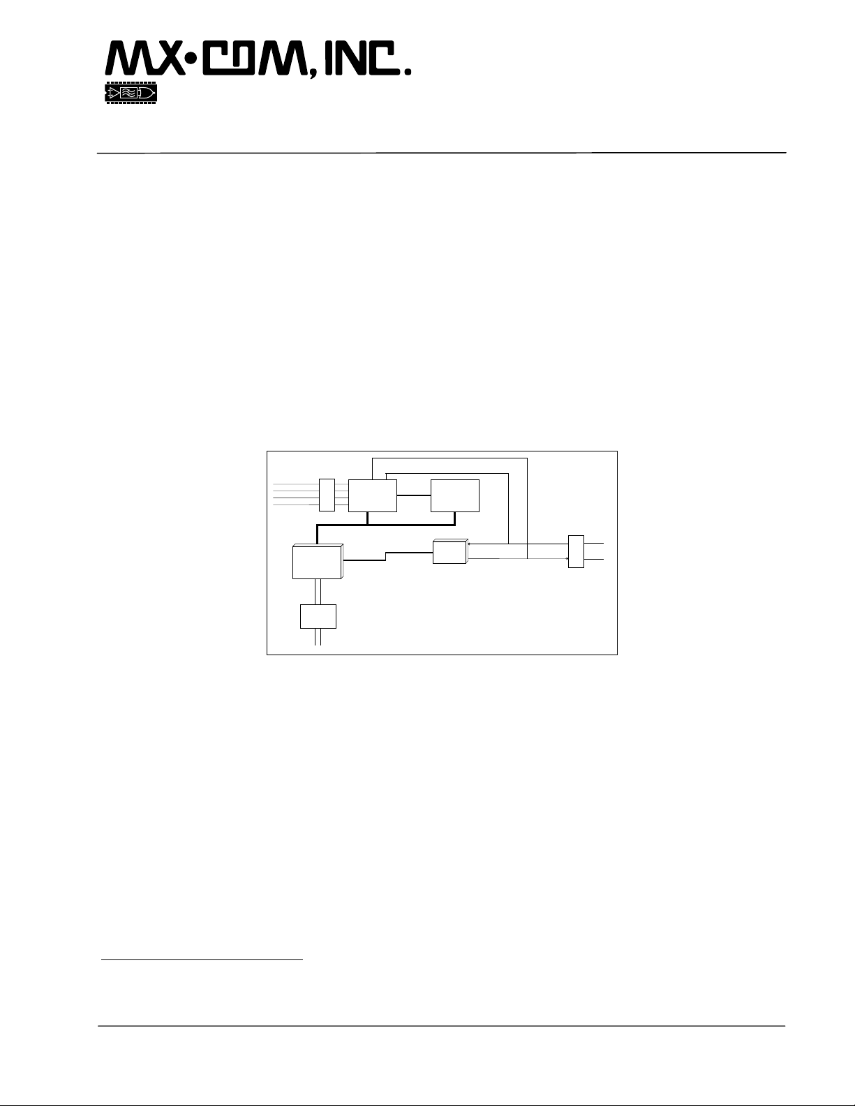
ISDN Data and Telephony
Protocol Engine
Advance Information
Features Applications
S/T Interface
Parallel BUS
CMX218
1
AM79C30
Controller
S/T BUS
+ Codec
IOM2 BUS
C-BUS
•
•
•
•
•
•
•
•
Dual FIFO
HDLC Driver
PSB-21525
CMX605
Feature Phones with Data Interfaces
Pay-Phones
PABX Telephones + Data
Data Terminal Adapters
EPOS Terminals
Remote Metering and Alarm Systems
H.320 Video Phones
Reference Designs Available
DTMF Rx
CLI
A
S
L
POTS 1
I
C
B
•
Supports ITU Specifications
•
Supports Incoming and Outgoing Calls
•
Auto-bauding and Auto-parity
•
Hayes Compatible 'AT' Command Set
•
V.120 Rate Adaption
•
PPP Async to Sync Conversion
•
Supports CTR3 Approval
•
Voice and User Data via B Channels
Full API Available
•
RS232
Interface
Driver
RS232
The CMX218 is an ISDN data and telephony protocol engine which implements the lower level ISDN interface
and communicates with the CMX605 and other standard devices to form a fully integrated ISDN chipset for
both voice and data communications. The CMX218 puts all the main data processing elements in a single
device. No ISDN software has to be written and simple ‘Plug and Play’ design results. This reduces
development time and provides a highly cost-effective hardware solution. By using proven circuit designs, the
designer can move quickly from initial concept through design in to manufacture.
The CMX218 supports one voice port over the ISDN Line, which can be used to provide ISDN telephony
services or a POTS line interface, and a single data channel, capable of operation at 115,200 bps. The
CMX218 features a full set of ‘Hayes’ compatible AT command codes on its asynchronous data interface, in
addition to providing keypad-configurable voice telephony services. The CMX218’s feature set and
architecture allow most analog systems to be converted to an ISDN equivalent with enhanced features.
The CMX218 is designed to work with the AMD 79C30 S/T bus interface, the Siemens PSB-21525 HDLC
formatter and the MX-COM CMX605 POTS interface circuit, and also comes complete with embedded
applications software. To support the CMX218, MX-COM can also provide licensed reference designs on
user request. A flexible Applications Program Interface (API) allows users to customize the features and
operation of their own design. The CMX218 is available in an 80-pin QFP (CMX218S1) package.
1
The CMX218 is a data processor integrated circuit that supports the protocol layers 1, 2 and 3 of the ISDN protocol stack in accordance
with the specifications of CCITT (now ITU). These specifications, which are widely used around the world, might not be supported within
the U.S.
MX-COM, Inc 2000 MX-COM, Inc.
4800 Bethania Station Road, Winston-Salem, NC, 27105-1201, USA Doc. # 20480215.001
www.mxcom.com tel: 800 638 5577 336 744 5050 fax: 336 744 5054 2000 Chiron Technology Limited
All trademarks and service marks are held by their respective companies
Page 2

ISDN Data and Telephony Protocol Engine (no X.25) 2 CMX218 Advance Information
CONTENTS
Section Page
1. Block Diagram................................................................................................................4
2. Signal List.......................................................................................................................5
3. External Components....................................................................................................7
4. General Description.......................................................................................................8
4.1 Glossary .............................................................................................................................. 9
4.2 Initialization........................................................................................................................ 10
4.3 ISDN Interface................................................................................................................... 10
4.3.1 Activation..............................................................................................................................10
4.3.2 De-activation or Line Disconnection.....................................................................................10
4.3.3 Line Failure Detection ..........................................................................................................10
4.3.4 Incoming Calls......................................................................................................................10
4.3.5 Multiple Subscriber Numbering............................................................................................11
4.3.6 Channel Mapping.................................................................................................................11
4.4 POTS Configuration .......................................................................................................... 12
4.4.1 Configuration and Control via DTMF Keypad.......................................................................12
4.5 POTS Operation................................................................................................................ 13
4.5.1 Keypad Operation ................................................................................................................13
4.5.2 Incoming POTS Calls...........................................................................................................13
4.5.3 Outgoing POTS Calls...........................................................................................................14
4.5.4 Connected Calls...................................................................................................................14
4.5.5 Call Clearing.........................................................................................................................14
4.6 Data Configuration............................................................................................................. 15
4.6.1 Hayes Command Set ...........................................................................................................15
4.6.2 Hayes Register Set ..............................................................................................................19
4.7 Data Operation..................................................................................................................20
4.7.1 Incoming B-Channel Data Calls...........................................................................................20
4.7.2 Outgoing B-Channel Data Calls...........................................................................................21
4.7.3 Connected Calls...................................................................................................................21
4.7.4 Call Clearing.........................................................................................................................21
4.8 Application Programmer's Interface................................................................................... 21
4.9 Hardware Description........................................................................................................ 22
4.9.1 LED Status Indicators (LED1 to LED9, and ILFI).................................................................22
5. Application Notes ........................................................................................................23
5.1 General.............................................................................................................................. 23
5.2 Approvals........................................................................................................................... 23
MX-COM, Inc 2000 MX-COM, Inc.
4800 Bethania Station Road, Winston-Salem, NC, 27105-1201, USA Doc. # 20480215.001
www.mxcom.com tel: 800 638 5577 336 744 5050 fax: 336 744 5054 2000 Chiron Technology Limited
All trademarks and service marks are held by their respective companies
Page 3

ISDN Data and Telephony Protocol Engine (no X.25) 3 CMX218 Advance Information
6. Performance Specification..........................................................................................24
6.1 Electrical Performance ...................................................................................................... 24
6.1.1 Absolute Maximum Ratings..................................................................................................24
6.1.2 Operating Limits...................................................................................................................24
6.1.3 Operating Characteristics.....................................................................................................25
6.2 Packaging.......................................................................................................................... 30
MX-COM, Inc. reserves the right to change specifications at any time and without notice.
MX-COM, Inc 2000 MX-COM, Inc.
4800 Bethania Station Road, Winston-Salem, NC, 27105-1201, USA Doc. # 20480215.001
www.mxcom.com tel: 800 638 5577 336 744 5050 fax: 336 744 5054 2000 Chiron Technology Limited
All trademarks and service marks are held by their respective companies
Page 4
ISDN Data and Telephony Protocol Engine (no X.25) 4 CMX218 Advance Information
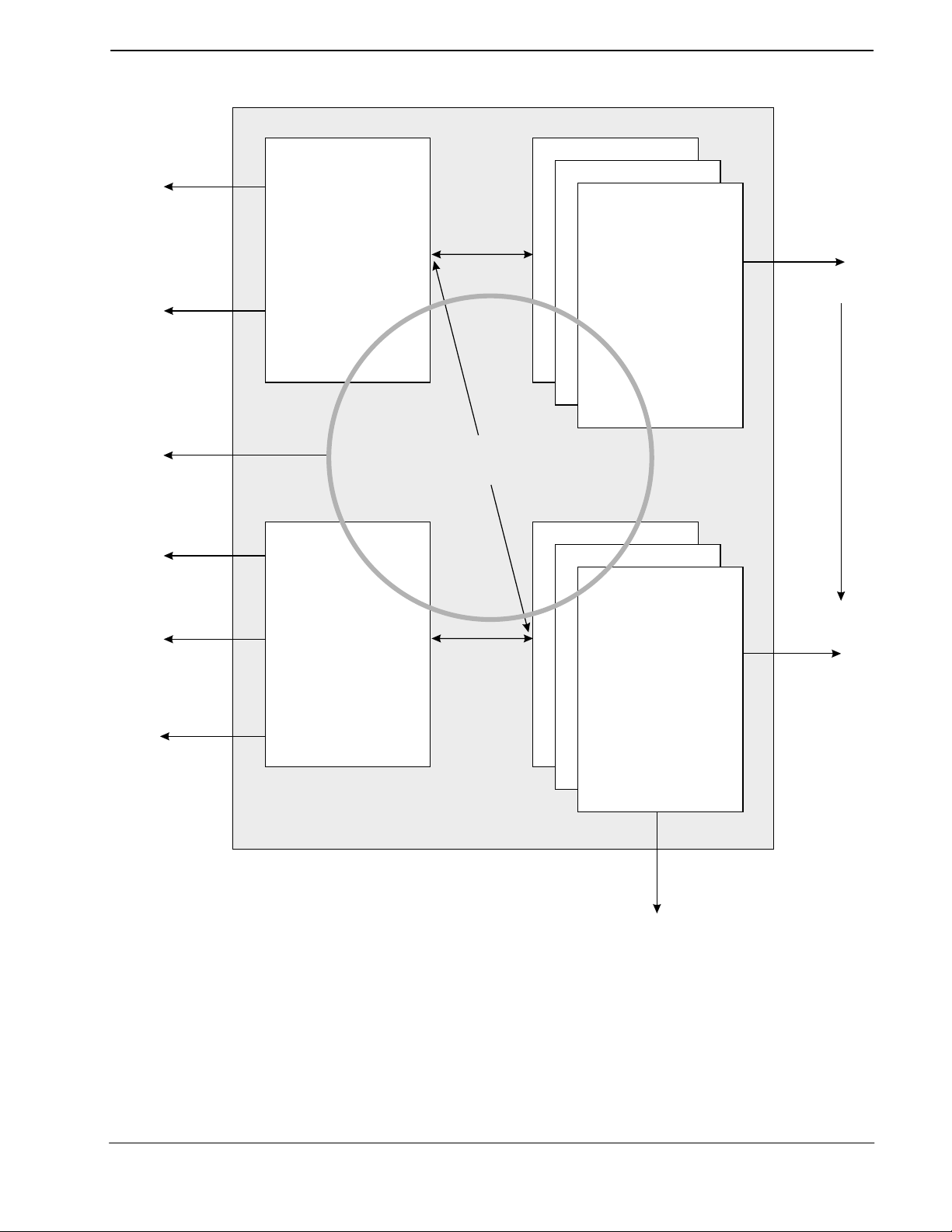
1. Block Diagram
Serial
Data Port
LED Status
Indicators
System Memory
and NVRAM
Hayes AT
Command
Handler
Task Scheduler,
Memory Manager,
Timers and Task Mailing
ISDN
B-channel
Data
Protocol
Stacks
HDLC
Chip
SLIC
CMX605
DTMF Detector
and
Caller Display
LED Status
Indicators
POTS Port
Handler
Figure 1: Block Diagram
D-channel
Protocol
Stacks
LED Status
Indicator
ISDN
ISDN
Interface
Chip
MX-COM, Inc 2000 MX-COM, Inc.
4800 Bethania Station Road, Winston-Salem, NC, 27105-1201, USA Doc. # 20480215.001
www.mxcom.com tel: 800 638 5577 336 744 5050 fax: 336 744 5054 2000 Chiron Technology Limited
All trademarks and service marks are held by their respective companies
Page 5

ISDN Data and Telephony Protocol Engine (no X.25) 5 CMX218 Advance Information
2. Signal List
S1 Package Signal
Pin No. Name Type
1 SCL output EEPROM - Serial Clock
2 SDA bi-directional EEPROM - Serial Data
3 ISDNRST output ISDN S-interface Chip Reset
4 RI1 output RS232 Port1 Ring Indicator (high when inactive)
5 DCD1 output RS232 Port1 Data Carrier Detect (high when inactive)
6 CTS1 output RS232 Port1 Clear To Send (high when inactive)
7
8
RST
DV
DD1
input CMX218 Chip Reset (active low)
Power
The digital positive supply rail. Levels and voltages are
dependent upon this supply. This pin should be decoupled
9
XTAL
to DV
output The output of the on-chip Xtal oscillator inverter
by a capacitor
SS
10 XTAL input The input to the oscillator inverter from the Xtal circuit
DV
11
SS1
power The digital negative supply rail (ground)
12 LED1 output POTS Port Off-Hook Indicator (HK1)
13 LED2 output RS232 Port 1 Auto-Answer Indicator (AA)
14 LED3 output RS232 Port 1 Data Carrier Detect Indicator (DCD)
15 LED4 output RS232 Port 1 Ready To Send Indicator (RTS)
16 LED5 output RS232 Port 1 Receive Data Indicator (RXD)
17 LED6 output RS232 Port 1 Transmit Data Indicator (TXD)
18 LED7 output RS232 Port 1 Data Terminal Ready Indicator (DTR)
19 LED8 output ISDN Line Activated Indicator (AR)
20
ST
output Watchdog Timer Stimulus
21 LED9 output POTS Port Call Connected Indicator (CN1)
22
23
WR
RD
output Memory Write Access Strobe
output Memory Read Access Strobe
24 A19 output Memory and Peripheral Address Bus
25 A18 output Memory and Peripheral Address Bus
26 A17 output Memory and Peripheral Address Bus
27 A16 output Memory and Peripheral Address Bus
28 A15 output Memory and Peripheral Address Bus
29 A14 output Memory and Peripheral Address Bus
30 A13 output Memory and Peripheral Address Bus
31 A12 output Memory and Peripheral Address Bus
32 A11 output Memory and Peripheral Address Bus
33 A10 output Memory and Peripheral Address Bus
34 A9 output Memory and Peripheral Address Bus
35 A8 output Memory and Peripheral Address Bus
36 A/D7 bi-directional Memory and Peripheral Address and Data Bus
37 A/D6 bi-directional Memory and Peripheral Address and Data Bus
38 A/D5 bi-directional Memory and Peripheral Address and Data Bus
Description
MX-COM, Inc 2000 MX-COM, Inc.
4800 Bethania Station Road, Winston-Salem, NC, 27105-1201, USA Doc. # 20480215.001
www.mxcom.com tel: 800 638 5577 336 744 5050 fax: 336 744 5054 2000 Chiron Technology Limited
All trademarks and service marks are held by their respective companies
Page 6

ISDN Data and Telephony Protocol Engine (no X.25) 6 CMX218 Advance Information
S1 Package Signal
Description
Pin No. Name Type
39 A/D4 bi-directional Memory and Peripheral Address and Data Bus
40 A/D3 bi-directional Memory and Peripheral Address and Data Bus
41 A/D2 bi-directional Memory and Peripheral Address and Data Bus
42 A/D1 bi-directional Memory and Peripheral Address and Data Bus
43 A/D0 bi-directional Memory and Peripheral Address and Data Bus
44 ASTB output Address/Data Bus Strobe (data bus selected if low)
DV
45
46 ~ input
SS0
power The digital negative supply rail (ground)
For manufacturer's use only. Connect to DV
directly
SS
47 PSBRES output HDLC Chip Reset
48 N/C output Do not make any connection to this pin
49 N/C output Do not make any connection to this pin
50 API-RXD input API/RS232 Port 2 Rx Data (inactive = high)
51 API-TXD output API/RS232 Port 2 Tx Data (high when inactive)
52 N/C output Do not make any connection to this pin
53 N/C output Do not make any connection to this pin
54 ILFI output ISDN Line Failure Indicator
55
DV
DD0
power
The digital positive supply rail. Levels and voltages are
dependent upon this supply. This pin should be decoupled
to DV
by a capacitor
SS
56 RING1 output POTS Port Ringing Generator (low when not ringing)
57
1RING
58 CLIP1 output
output POTS Port Ringing Generator (high when not ringing)
POTS Port Line Voltage Adjustment (low when sending FSK
to a Caller Display unit. If low, it makes the SLIC present a
high impedance to the POTS line)
59 ILINE1 input
POTS Port Hook Switch Status Detector
(on-hook = low)
60
∼
input
For manufacturers’ use only. Connect to DV
SS
directly
61 REPLY input CMX605 C-BUS Interface - Reply Data
62 CMD-DATA output CMX605 C-BUS Interface - Command Data
63 SER-CLK output CMX605 C-BUS Interface - Serial Clock
64
65
66
67
AV
AV
AV
DD
REF1
SS
1CS
power
The positive analog supply rail. Levels and voltages are
dependent upon this supply. This pin should be decoupled
power
to AV
A/D Reference Voltage. Connect to AVDD directly
by a capacitor
SS
power The negative analog supply rail (ground)
output CMX605 C-BUS Interface (chip select for POTS Port)
68 N/C output Do not make any connection to this pin
69
70
AV
AV
REF2
REF3
power
power
71 NMI input
D/A Reference Voltage. Connect to AVDD directly
D/A Reference Voltage. Connect to AVSS directly
For manufacturer's use only. Connect to DV
directly
SS
72 API-INT input API Interrupt (inactive = high)
73
IRQ
input CMX605 C-BUS Interface - Interrupt (inactive = high)
MX-COM, Inc 2000 MX-COM, Inc.
4800 Bethania Station Road, Winston-Salem, NC, 27105-1201, USA Doc. # 20480215.001
www.mxcom.com tel: 800 638 5577 336 744 5050 fax: 336 744 5054 2000 Chiron Technology Limited
All trademarks and service marks are held by their respective companies
Page 7
ISDN Data and Telephony Protocol Engine (no X.25) 7 CMX218 Advance Information
S1 Package Signal
Description
Pin No. Name Type
74 PSBINT input HDLC Chip Interrupt
75 RXD1 input RS232 Port 1 Received Data - used for autobauding
76 RTS1 input RS232 Port 1 Ready To Send (inactive = high)
77 ISDNINT input ISDN S-interface Chip Interrupt
78 DTR1 input RS232 Port 1 Data Terminal Ready (inactive = high)
79 RXD1 input RS232 Port 1 Received Data (inactive = high)
80 TXD1 output RS232 Port 1 Transmitted Data (high when inactive)
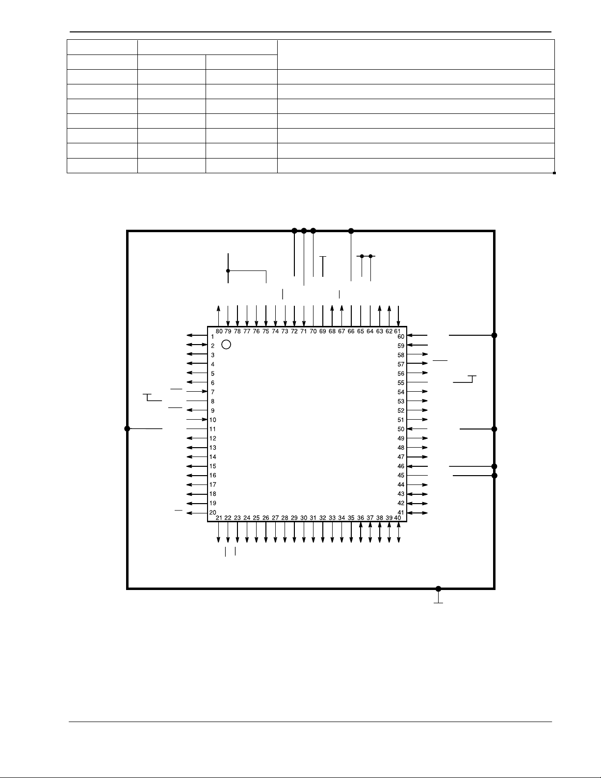
3. External Components
V
DD
SCL
SDA
ISDNRST
RI1
DCD1
CTS1
RST
DV
DD1
XTAL
XTAL
DV
SS1
LED1
LED2
LED3
LED4
LED5
LED6
LED7
LED8
N/C
CS1
V
DD
SS
REF1
DD
AV
AV
AV
REPLY
SER-CLK
CMD-DATA
(V )
SS
ILINE1
CLIP1
RING1
RING1
DV
ILFI
N/C
N/C
API-TXD
API-RXD
N/C
N/C
PSBRES
(V )
DV
ASTB
A/D0
A/D1
A/D2
SS
DD0
SS0
V
DD
V
DD
RXD1
REF2
REF3
AV
TXD1
RXD1
DTR1
RTS1
ISDNINT
RXD1
PSBINT
IRQ
API-INT
NMI
AV
CMX218S1
ST
LED9
WR
RD
A19
A18
A17
A16
A15
A14
A13
A12
A11
A10
A9
A/D7
A/D6
A/D5
A/D4
A/D3
V
SS
A8
Figure 2: CMX218 Pin Out
This product is to be used as part of a chip-set. Please refer to the Applications Section
Note:
(See Section 5) for details of the recommended chip-set.
MX-COM, Inc 2000 MX-COM, Inc.
4800 Bethania Station Road, Winston-Salem, NC, 27105-1201, USA Doc. # 20480215.001
www.mxcom.com tel: 800 638 5577 336 744 5050 fax: 336 744 5054 2000 Chiron Technology Limited
All trademarks and service marks are held by their respective companies
Page 8

ISDN Data and Telephony Protocol Engine (no X.25) 8 CMX218 Advance Information
4. General Description
The CMX218 is a single-chip data processor that has been mask programmed with firmware to implement an
ISDN protocol stack. This enables the CMX218 to interface an analog (POTS) port and a digital (RS232) port
to an ISDN S-bus network connection. Key variables are stored in an external EEPROM and the user can
provide additional features by adding external ROM and RAM. Access to the firmware Application
Programmer's Interface (API) facilitates the seamless integration of the user's additional features with the preprogrammed ISDN to POTS and RS232 interfaces.
The CMX218 is intended for use as part of an ISDN chipset and all descriptions in this data sheet refer to this
implementation, which is shown diagrammatically in Figure 3. The use of alternative chipsets is not
supported.
The firmware supports connection to an ISDN S-bus
controller and the AMD AM79C30 ST controller with integral PCM codec for a single POTS port.
The CMX218 interfaces with a CMX605 Tone Generator and DTMF Receiver chip, which decodes incoming
DTMF tones and generates certain call progress signals (e.g. busy tone) normally originating from an analog
telephone exchange. The firmware translates the CMX605 data into ISDN D-channel commands and vice
versa to support both incoming and outgoing calls. For the ISDN interface, D-channel commands sufficient
for standard telephony applications are implemented. With the aid of a small amount of discrete circuitry,
exchange battery voltage, ringing current, line reversal and off-hook detection are also supported, to complete
the POTS interface.
The CMX218 also provides a data port that can drive a standard RS232 interface with the aid of a Maxim
MAX238, or similar, level converter. The firmware provides support for incoming and outgoing data calls,
RS232 auto-bauding from 9600bps to 115200bps, auto parity detection, RTS/CTS flow control, call clearing
on loss of DTR, V.120 rate adaption, PPP async to sync conversion and a comprehensive set of Hayes
commands (which facilitate the use of normal PC-based modem software). The CMX218 has dedicated
outputs for visible indicators (LEDs) that can be used to provide information on the call status. Support for
Multiple Subscriber Numbering is also included in the firmware.
The CMX218 can be configured either by means of keypad (DTMF) programming via the POTS port or by
means of an extended Hayes command set via the RS232 port. Configuration parameters allow the user to
change (for example) the format and cadence of the ringing signal, so as to facilitate use of the CMX218 in
different countries. Each POTS and RS232 interface is able to configure the variables relevant to its own use.
An Application Programmer's Interface (API) is available and is described separately in Section 4.8. Further
details are available on completion of a Non-Disclosure Agreement. Please contact MX-COM directly for
further details.
The firmware and finite state machine embedded in the CMX218 have been used in products that have
gained ETSI CTR3 approval.
network interface via the Siemens PSB21525 HDLC
MX-COM, Inc 2000 MX-COM, Inc.
4800 Bethania Station Road, Winston-Salem, NC, 27105-1201, USA Doc. # 20480215.001
www.mxcom.com tel: 800 638 5577 336 744 5050 fax: 336 744 5054 2000 Chiron Technology Limited
All trademarks and service marks are held by their respective companies
Page 9

ISDN Data and Telephony Protocol Engine (no X.25) 9 CMX218 Advance Information
4.1 Glossary
ACCM
API
CIDCW
CLI
CRC
CTS
DCD
DDI
DTE
DTMF
DTR
HDLC
IA5
IE
ILFI
ISDN
LAPB
LAPD
LCGN
LED
LLI
MFO
MSN
NUA
NUI
PAD
PC
PCM
POTS
PPP
PVC
RI
RNR
RR
RTS
SABM
SABME
SLIC
SPM
SVC
TEI
Asynchronous Control Character Map
Application Programmer’s Interface
Caller Identification During Call Waiting
Calling Line Identification
Cyclic Redundancy Check
Clear to Send
Data Carrier Detect
Direct Dialing Inwards
Data Terminal Equipment
Dual Tone Multiple Frequency
Data Terminal Ready
High Level Data Link Control
International Alphabet No 5
Information Element
ISDN Line Failure Indicator
Integrated Services Digital Network
Link Access Procedure - Balanced
Link Access Procedure on the D-Channel
Logical Channel Group Number
Light Emitting Diode
Logical Link Identifier
Multiple Frame Operation
Multiple Subscriber Numbering
Network User Address
Network User Identification
Packet Assembler/Disassembler
Personal Computer
Pulse Code Modulation
Plain Old (Analog) Telephone Service
Point to Point Protocol
Permanent Virtual Circuit
Ring Indication
Receiver Not Ready
Receiver Ready
Ready to Send
Set Asynchronous Balanced Mode
Set Asynchronous Balanced Mode Extended
Subscriber Line Interface Circuit
Subscriber Pulse Metering
Switched Virtual Circuit
Terminal Endpoint Identifier
MX-COM, Inc 2000 MX-COM, Inc.
4800 Bethania Station Road, Winston-Salem, NC, 27105-1201, USA Doc. # 20480215.001
www.mxcom.com tel: 800 638 5577 336 744 5050 fax: 336 744 5054 2000 Chiron Technology Limited
All trademarks and service marks are held by their respective companies
Page 10

ISDN Data and Telephony Protocol Engine (no X.25) 10 CMX218 Advance Information
4.2 Initialization
On power-up, the CMX218 assumes its default values, which are factory programmed into the firmware. It
then performs a self-test, during which all of the LED pins and the ILFI pin are held high for 3s. If the test is
unsuccessful, the CMX218 remains in this condition.
If the test is successful, the CMX218 reads its preset values from the attached EEPROM and examines the
state of the ISDN link (i.e. Layer 1) before commencing normal operation. On power-up, the ISDN link is deactivated, the POTS port is assumed to be on-hook, ringing is disabled and the RS232 port is in the Hayes
command state.
4.3 ISDN Interface
Simultaneous voice and data calls are possible but only one of each type. If a call is active (e.g. ringing,
connected or clearing down) and an incoming call of the same type (data or voice) is received, that call will be
rejected with user busy as the cause. Incoming calls are firstly checked for other calls present, then the MSN
is checked for validity, then the channel mapping, so that responses will be handled accordingly.
When channel mapping is enabled, outgoing calls will request the channel enabled. When not enabled, a
request for any channel is made. If no free channels are available for outgoing calls, a locally generated busy
tone is returned to the analog port or the appropriate Data Call Result Code is returned to the digital port.
4.3.1 Activation
Activation occurs in the following circumstances:
•
The ISDN network activates.
•
The device connected to the analog port goes off hook.
•
The device connected to the data port sends a Hayes dial command.
The Terminal Endpoint Identifier (TEI) is either negotiated (Hayes register !C7 = 64) or fixed (Hayes register
!C7 = 0 to 63). Line powering of the CMX218 is not supported.
The 'AR' indicator (LED8) toggles between high and low states when the CMX218 is powered up, and
remains constantly low once the CMX218 identifies an activated ISDN line.
ISDN line power detection is not implemented and the CMX218 will negotiate a new TEI on any new network
activation.
4.3.2 De-activation or Line Disconnection
De-activation or line disconnection causes the TEI to be removed. Upon re-connection the CMX218 will only
be re-activated and request a new TEI when one of the conditions in the above section is met.
4.3.3 Line Failure Detection
If the line failure detection parameter is enabled (either via the POTS port or via the RS232 interface) the
CMX218 will check that Layer 2 communications are active every sample period of 30 seconds. If Layer 2
communications are not active, the CMX218 will attempt to activate them. If they remain inactive for 2 sample
periods, the line is deemed to have failed, so then the ILFI pin is set high and both RINGP1 and RINGN1 pins
are set low. The CMX218 continues to attempt to activate the line and if it becomes active and stays active
for 2 sample periods, then the ILFI pin is set low and RINGP1 and RINGN1 pins are restored to their default
settings.
4.3.4 Incoming Calls
Incoming voice calls and calls from analog lines are directed to the analog port and all other incoming calls
are directed to the RS232 port.
MX-COM, Inc 2000 MX-COM, Inc.
4800 Bethania Station Road, Winston-Salem, NC, 27105-1201, USA Doc. # 20480215.001
www.mxcom.com tel: 800 638 5577 336 744 5050 fax: 336 744 5054 2000 Chiron Technology Limited
All trademarks and service marks are held by their respective companies
Page 11

ISDN Data and Telephony Protocol Engine (no X.25) 11 CMX218 Advance Information
4.3.5 Multiple Subscriber Numbering
Multiple Subscriber Numbering (MSN) enables each POTS or RS232 port of the CMX218 to have its own
telephone number. Up to 23 digits can be saved as the MSN for each port.
All incoming SETUP messages will be checked for the presence of a Called Party Number Information
Element (IE). If one is present it is compared with the saved MSN number (if present), starting with the last
digit of both numbers. Comparison continues until there are no more numbers in the MSN saved number or
the incoming Called Party Number or there is a difference between the numbers. The MSN is said to match if
the saved MSN and the incoming calls’ Called Party Number are the same for the duration of the shorter
number (i.e. if the digit ‘1’ is saved and the received Called Party Number is 654321, then the MSN matches).
If there is no saved MSN, the Called Party Number is ignored and call processing continues.
When there is a saved MSN and the Calling Party Number transmit is enabled, all outgoing call SETUP
messages will contain a Calling Party Number Information Element.
Note:
1. When a CMX218 with MSN saved and Calling Party Number transmit enabled is connected to some
exchanges, no dial tone is heard when going off-hook.
2. Disabling the Calling Party Number transmit will mean that the called party may not receive the Calling
Line Identification (CLI), or if they do receive a CLI it will probably be the base number and not the
number specific to the calling telephone.
4.3.6 Channel Mapping
It is possible to configure the CMX218 so that analog and/or digital ports will only originate calls to and
respond to calls from a specific ISDN B-channel. This is a useful feature if, for example, you wish to have a
Hunt Group on your ISDN line and only want one voice or data port to ring on an incoming call.
MX-COM, Inc 2000 MX-COM, Inc.
4800 Bethania Station Road, Winston-Salem, NC, 27105-1201, USA Doc. # 20480215.001
www.mxcom.com tel: 800 638 5577 336 744 5050 fax: 336 744 5054 2000 Chiron Technology Limited
All trademarks and service marks are held by their respective companies
Page 12

ISDN Data and Telephony Protocol Engine (no X.25) 12 CMX218 Advance Information
4.4 POTS Configuration
4.4.1 Configuration and Control via DTMF Keypad
Configuration can be carried out at any time by causing the POTS port to go off-hook and then immediately
entering a configuration sequence of DTMF tones. The sequence signaled to the CMX218 will determine the
configuration to be performed, as shown in the following table.
Configuration
Sequence
$02$
$90$
$90$
$93$
$93$
$94$
$94$
$95$
$95$
$96$
$96$
$97$
$97$
$9$$
1234567890#
Once the ‘
#
#
n#
#
n#
#
n#
#
1#
#
1#
#
1#
$’ has been recognized, each digit pressed is then checked for validity as a configuration
Test watchdog
Clear MSN Clears any saved digits N/A
Save Multiple Subscriber
Number (MSN)
Clear country code Country code is set to UK by default N/A
Change country code
Clear channel mapping
Enable channel mapping Where n = 1 or 2 for the appropriate channel.
Disable Calling Party No.
transmit
Enable Calling Party No.
transmit
Disable DDI transmit
Enable DDI transmit
Disable line failure
detection
Enable line failure
detection
Initialize all configurations.
sequence. If any digit pressed is not a valid configuration digit, all digits pressed so far will be transmitted to
the network in INFORMATION messages as Keypad Information Elements, until a ‘#’ is entered (with the
exception of ‘$
#’ being entered, see Keypad Operation below). If the first four digits received are a valid
configuration sequence then the configuration mode is entered. When a valid configuration has been
completed the CMX218 will send a single DTMF tone to the POTS port. If a valid configuration sequence is
received but subsequent digits are invalid, then subsequent digits entered will be ignored and two DTMF
tones will be sent to the POTS port.
If the port goes on-hook part way through configuration, it will cause any digits received so far to be ignored.
Configurations can be performed consecutively with the exception of the test function (where the attached
handset must be replaced immediately after the configuration has been audibly signaled to the POTS port).
All configurations entered will be retained after a power-down as they are stored in the external EEPROM.
Name Description Default
Puts the CMX218 into a permanent loop, not
updating the external watchdog counter, so after
2s it should reset.
n = MSN (up to 23 digits) Clear
n = country code
0 = UK
1 = Belgium
2 = Rest of Europe
Incoming calls on any channel are accepted
(provided other parameters are valid e.g. MSN).
Outgoing call SETUP messages do not contain
any Calling Party Number Information Elements.
Outgoing call SETUP messages contain Calling
Party Number Information Element with number
set to saved MSN (if a number is present).
Prevents digits being transmitted to the POTS
port upon call connection.
Upon connection of a call on the POTS port, if
there was a Called Party Number Information
Element present in the incoming call setup
message, the digits are sent as DTMF tones to
the POTS port.
Once the CMX218 is de-activated it stays deactivated until the network re-activates it or an
outgoing call needs to be made.
The CMX218 checks to see if the ISDN line is
activated and Layer 2 communications can be
made. It then sets the ILFI pin accordingly.
Resets all of the configuration variables back to
their default values.
N/A
UK
N/A
No channel
map
N/A
Enabled
N/A
Disabled
N/A
Disabled
N/A
MX-COM, Inc 2000 MX-COM, Inc.
4800 Bethania Station Road, Winston-Salem, NC, 27105-1201, USA Doc. # 20480215.001
www.mxcom.com tel: 800 638 5577 336 744 5050 fax: 336 744 5054 2000 Chiron Technology Limited
All trademarks and service marks are held by their respective companies
Page 13

ISDN Data and Telephony Protocol Engine (no X.25) 13 CMX218 Advance Information
4.5 POTS Operation
4.5.1 Keypad Operation
The CMX218 supports ISDN keypad messages for control of Network Supplementary services either before
or during call establishment. When dialing a number (i.e. off-hook and dial tone audible on POTS port), or if a
call has been disconnected by the network but the POTS port has not yet gone on-hook, any keypad string
entered will be sent to the network as ‘Keypad Information Elements’ within INFORMATION messages.
Keypad strings are defined as the following sequences of digits, with the exception of the configuration strings
defined in the previous section:
...#
$
#
...#
$
#
...#
When a call is connected, pressing the recall key results in all subsequent key presses being sent to the
network as ‘Keypad Information Elements’ within INFORMATION messages, until the handset is replaced.
The tones generated by the key presses are also passed down the B-channel, so the remote user will be able
to hear them.
4.5.2 Incoming POTS Calls
An incoming POTS call is identified by the Bearer Capability Information Element of the SETUP message
being set to ‘Speech' or ‘3.1kHz Audio’. The call will be routed to the POTS port if it satisfies the following
three conditions:
•
The port is on-hook.
•
The MSN saved for the port matches the Called Number in the incoming SETUP message, or no MSN
is specified for the port, or there is no Called Number in the SETUP message. See Section 4.3.5 for
details of POTS port MSN selection.
•
The ISDN B-channel on which the call is placed (as indicated in the SETUP message) is compatible
with the channel mapping configuration for the port. See Section 4.3.6 for details of POTS port channel
mapping selection.
When the call is routed to the port, the ringing signal for that port will be applied by means of the RINGP1 and
RINGN1 pins.
The call is answered when the port with ringing signal goes off-hook. The ringing signal is then stopped and
the ISDN call is connected to that port.
MX-COM, Inc 2000 MX-COM, Inc.
4800 Bethania Station Road, Winston-Salem, NC, 27105-1201, USA Doc. # 20480215.001
www.mxcom.com tel: 800 638 5577 336 744 5050 fax: 336 744 5054 2000 Chiron Technology Limited
All trademarks and service marks are held by their respective companies
Page 14

ISDN Data and Telephony Protocol Engine (no X.25) 14 CMX218 Advance Information
4.5.3 Outgoing POTS Calls
Outgoing calls are initiated when the POTS port goes off-hook. An ISDN SETUP message is sent to the
network with the Bearer Capability Information Element set to 'Speech'. The dial tone presented by the
network on that ISDN B-channel that was selected by channel mapping (See Section 4.3.6), will be routed to
the POTS port.
When DTMF tones are received from the POTS port, they are sent to the network either as Called Party
Number or Keypad Information Elements. Keypad Information Elements are discussed in Section 4.5.1.
Receipt of a valid DTMF tone will prompt its conversion to IA5 coded digits, as shown in the following table
(IA5 hex digits are in brackets). If the first valid digit to be received is a ‘$’ then the configuration mode is
entered and subsequent digits will be monitored and saved as indicated in Section 4.4.1. If the first tone
received is not a ‘$’ or ‘#’ (See Section 4.5.1) that digit and all subsequent digits will be passed to the network
in an INFORMATION message as a Called Party Number Information Element. Digits received before the
network has returned the SETUP ACK message are saved. Upon receipt of the SETUP ACK any saved
digits will be transmitted.
The DTMF tone mapping is as shown below:
Low Group
(Hz)
High Group (Hz)
1209 1336 1477 1633
697 1 (31) 2 (32) 3 (33) A (not used)
770 4 (34) 5 (35) 6 (36) B (not used)
852 7 (37) 8 (38) 9 (39) C (not used)
941
$(2A) 0 (30)
# (23)
D (not used)
Once the network has indicated that the full number has been received, no further digits will be sent to the
network. All tones and announcements from the network (e.g. ringing, NU, busy etc) and audio (if the call is
connected) will be routed to the POTS port, until that port goes on-hook.
4.5.4 Connected Calls
Once a call is connected to the analog port, whether it was incoming or outgoing, a LED indicator pin is set
high to indicate that the call is connected. See Section 4.9.1 for details of the LED indicator pins. Once the
call is disconnected, either by receipt of a DISCONNECT message from the network or an on-hook indication,
that LED indicator pin is set low.
During a call, if a Recall (i.e. a line break of appropriate length) is received from the POTS port, the CMX218
will start to look for DTMF tones received on the POTS port. Any tones received will then be sent to the
network in ISDN INFORMATION messages, as Keypad Information Elements
.
4.5.5 Call Clearing
The call is cleared either by the port going on-hook or by the ISDN network. Note that the ISDN B-channel
that was being used is not released until the POTS port has gone on-hook.
MX-COM, Inc 2000 MX-COM, Inc.
4800 Bethania Station Road, Winston-Salem, NC, 27105-1201, USA Doc. # 20480215.001
www.mxcom.com tel: 800 638 5577 336 744 5050 fax: 336 744 5054 2000 Chiron Technology Limited
All trademarks and service marks are held by their respective companies
Page 15

ISDN Data and Telephony Protocol Engine (no X.25) 15 CMX218 Advance Information
4.6 Data Configuration
4.6.1 Hayes Command Set
The following Hayes commands are supported:
A - Answers a call
D - Dial
E - Echo Hayes commands or not
H - Hang-up
I3 - Firmware part number
Q - Result code display
V - Result code form
X - Result code set
&C - Carrier detect
&D - Data terminal ready
&F - Load factory default
&K - Flow control
&V - View active and stored profiles
Valid Hayes commands are responded to with an 'OK' result code. Invalid commands are rejected with an
'ERROR' result code.
If when entering an AT command, no command or register name suffix is supplied, a suffix of zero is
assumed. If when changing a register value, no value is supplied a value of zero or an empty string is
assumed: e.g. ATS0=<CR> is equivalent to ATS0=0<CR>.
If a data call is active when a command is entered, the command will be processed. The ATO command will
respond ‘OK’, but will not then enter the data state: it will stay in the command state.
Where commands set a parameter, these are saved in external EEPROM if they are entered correctly.
The CMX218 will auto-baud and auto-parity on Hayes commands at the following speeds:
•
9600bps
•
19200bps
•
38400bps
•
57600bps
•
115200bps
The auto-bauding process looks for the characters ‘AT’ or ‘at’ either as 8 bits no parity or 7 bits even, or odd,
parity. An error in the auto-bauding process results in auto-bauding being restarted.
After auto-bauding successfully, the CMX218 waits to receive a complete Hayes command line before
processing it. Embedded spaces are ignored and the case (upper or lower) of characters after the ‘AT’ does
not matter. The command line is terminated by <CR>, by 250 characters (not including the ‘AT’) or by a timeout (from successful auto-bauding on an ‘AT’) of 180 seconds.
All characters in the Hayes command, including the ‘AT’ and <CR> terminator are echoed (if E1 is set) by the
CMX218 as they are sent by the DTE.
Receipt of a backspace will cause the CMX218 to send a "back space, space, back space" sequence of
characters to the DTE to allow the terminal to clear its screen of the last character. Also the last character
received will be discarded unless the last characters received were the ‘AT’ used for auto-bauding, i.e. the
‘AT’ is never deleted.
The escape sequence ‘+++’ (with Guard Time = 1s before and after the sequence) will cause the CMX218 to
enter the command state from the data state and to return on ‘OK’ response. Sending an ATO command will
be ignored, i.e. the CMX218 remains in the command state.
&Z - Store directory number
MX-COM, Inc 2000 MX-COM, Inc.
4800 Bethania Station Road, Winston-Salem, NC, 27105-1201, USA Doc. # 20480215.001
www.mxcom.com tel: 800 638 5577 336 744 5050 fax: 336 744 5054 2000 Chiron Technology Limited
All trademarks and service marks are held by their respective companies
Page 16

ISDN Data and Telephony Protocol Engine (no X.25) 16 CMX218 Advance Information
The following is a more detailed description of the Hayes commands listed above:
A (Answer)
Format: ATA<CR>
Causes the CMX218 to answer an incoming data call, by sending a CONNECT message to the network. If
a CONNECT ACK is received the CMX218 enters the data state after returning a ‘CONNECT XXX’ result
code to the DTE on the RS232 port (where the XXX is the speed in baud). If a RELEASE, RELEASE
COMPLETE or DISCONNECT message is received a ‘NO CARRIER’ result code is returned. The
command is not valid if there is no incoming call and it will return ‘ERROR’.
D (Dial)
Format: ATD{DN}<CR>
Format: ATDT{DN}<CR>
Format: ATDP{DN}<CR>
{DN} is a directory number of up to 23 ASCII characters from 0..9, $ and #. This form of the ATD command
causes an outgoing SETUP message to be sent to the network with a Called Party Number Information
Element which contains the digits included in the command. Any commands that follow this command are
ignored.
If the CMX218 receives any character from the DTE after an ATD command, which causes a SETUP
message to be sent to the network, and before the call is connected, the attempt to make a call is abandoned,
i.e. a DISCONNECT message will be sent to the network and a ‘NO CARRIER’ result code returned.
Calls are established with the D command, irrespective of the state of the DTR pin. The result code response
is either:
'CONNECT' - call successful. The CMX218 will automatically enter the data state.
'NO CARRIER' - call rejected by the remote user or the network
'NO DIALTONE' - ISDN link down
'BUSY' - remote user busy and other causes
Calls are cleared in the following way:
i. The remote end or network clears the call by sending a DISCONNECT message or the ISDN line
fails/is removed: 'NO CARRIER' is sent to DTE.
ii. DTR is dropped (with a de-bounce period of 50ms) by DTE causing the CMX218 to send a
DISCONNECT message to the network and enter the disconnect state, awaiting a RELEASE
COMPLETE from the network. The CMX218 sends the 'OK' response when clearing of the ISDN call
is complete i.e. RELEASE and RELEASE COMPLETE messages have been transmitted across the
network, (dependant upon the state of &D command).
iii. The DTE issues the escape sequence ‘+++ ‘(with Guard Time = 1s before and after the sequence),
receives an 'OK' response and then issues the Hang-up command (see section on H command
below). The CMX218 sends the 'OK' response when clearing of the ISDN call is complete.
Incoming calls are indicated by a 'RING' result code. The call is automatically answered if S0 = 1 or more. If
S0 = 0 an ATA command must be entered, then a CONNECT message is sent to the network.
E (Echo)
Format: ATEn<CR>
Suffix n
Description
0 Echo off
1 (default) Echo on
This command tells the CMX218 whether or not to echo the characters received from the DTE when in
command mode. When echo is on, all non-control characters received from the DTE are echoed back to it.
H (Hang-up)
Format: ATH<CR>
Causes the CMX218 to clear the data call in progress. The command is not valid if there is no data call in
progress but always returns an ‘OK’ result code. It is only valid in the command state when a data call is in
operation, when it will send a DISCONNECT message to the network. Upon receipt of RELEASE, a
RELEASE COMPLETE is transmitted to the network and ‘OK’ returned to the DTE.
MX-COM, Inc 2000 MX-COM, Inc.
4800 Bethania Station Road, Winston-Salem, NC, 27105-1201, USA Doc. # 20480215.001
www.mxcom.com tel: 800 638 5577 336 744 5050 fax: 336 744 5054 2000 Chiron Technology Limited
All trademarks and service marks are held by their respective companies
Page 17

ISDN Data and Telephony Protocol Engine (no X.25) 17 CMX218 Advance Information
I3 (Firmware Part Number)
Format: ATI3<CR>
Causes the CMX218 to return the part code and revision level to the DTE:
"CMX218: Vn.nn" where n.nn = version number
Q (Result Code Display)
Format: ATQn<CR>
Suffix n
Description
0 (default) Result codes enabled
1 Result codes suppressed
2 Result codes are suppressed when an incoming call is received,
otherwise enabled
V (Result Code Form)
Format: ATVn<CR>
Suffix n
Description
0 Result codes sent as numbers (see Data Call Result Codes below)
1 (default) Result codes sent as words. This instructs the CMX218 to send the
result codes as words or numbers to the DTE.
X (Result Code Set)
Format: ATXn<CR>
Suffix n
Description
0 0...4
1 0...4, 12, 14, 18, 28, 31
2 0...4, 12, 14, 18, 28, 31
3 (default) 0...4, 6, 7, 12, 14, 18, 28, 31
4 0...4, 6, 7, 12, 14, 18, 28, 31
This command causes the CMX218 to limit the data call result codes used to a given set. See Data Call
Result Codes below for a list of codes and their meanings.
Data Call Result Codes
The data call result codes supported are:
Numbers
Words
0 'OK'
1 'CONNECT'
2 'RING'
3 'NO CARRIER'
4 'ERROR'
6 'NO DIALTONE'
7 'BUSY'
12 'CONNECT 9600'
14 'CONNECT 19200'
18 'CONNECT 57600'
28 'CONNECT 38400'
31 'CONNECT 115200'
&C (Carrier Detect)
Format: AT&Cn<CR>
Changes the operation of the RS232 DCD (Data Carrier Detect) signal.
Suffix n
Description
0 Ignore connection status; keep DCD high and LED3 pin low (i.e. ON).
1 (default) DCD tracks the status of the data connection, raised when the call
is connected, lowered when cleared. LED3 pin tracks the inverse status
of the DCD pin (i.e. high when data connection is cleared).
MX-COM, Inc 2000 MX-COM, Inc.
4800 Bethania Station Road, Winston-Salem, NC, 27105-1201, USA Doc. # 20480215.001
www.mxcom.com tel: 800 638 5577 336 744 5050 fax: 336 744 5054 2000 Chiron Technology Limited
All trademarks and service marks are held by their respective companies
Page 18

ISDN Data and Telephony Protocol Engine (no X.25) 18 CMX218 Advance Information
&D (Data Terminal Ready)
Format: AT&Dn<CR>
Determines the CMX218 operation if DTR is lowered during a call.
Suffix n
Description
0 No action
2 (default) B or D-channel data call is cleared and auto-answer is suspended until
DTR is raised again.
If &D2 is set and DTR is low when an incoming call is received, the call is accepted and Ring Indication is
sent to the DTE. If an incoming call has been accepted and &D2 is set when DTR is lowered, the call is
cleared.
&F (Load Factory Profile)
Format: AT&F<CR>
Sets the following commands and registers to their default values.
It does not change the %A !B, !C registers or the &Z command.
Commands: E Q V X &C &D &K
Registers: S0 S37 %B %D %E %L
Format: AT&F9<CR>
Sets all commands and registers to the default values and resets LED indicator and RS232 interface pins
accordingly.
&K (Flow Control)
Format: AT&Kn<CR>
Indicates the method of flow control to be used between the CMX218 and the DTE when in the data state.
There is no flow control when the CMX218 is in the command state.
Suffix n
Description
0 No flow control
3 (default) Bi-directional RTS/CTS signals
Flow control is only active when in an active data call, i.e. not when dealing with Hayes commands.
Flow control is applied to the DTE in the following situations:
i. The remote end signals flow control (the mechanism is protocol dependent).
ii. Several buffers of data are held waiting transmission across ISDN.
Flow control is applied to the remote end (the mechanism is protocol dependent) if excessive data is held
pending transmission to the DTE, so as to prevent local buffer overflow.
&V (View Active/Stored Profiles)
Format: AT&V<CR>
Causes the CMX218 to display the following command and register values for the stored profile:
Commands: E Q V X &C &D &K &Z
Registers: S0 S37 %A !C %E %B %D %L !B
&Z (Store Directory Number)
Format: AT&Z3={DN}<CR>
This command instructs the CMX218 to store a directory number. The stored directory number is then used
by the X.25 call setup as the ‘Calling NUA’.
A directory number consists of a string of characters from the set 0..9, $ and #. The ‘=‘ character can be
omitted. Where a store number is entered, only the value 3 will give an ‘OK’ response. The contents of the
&Z directory number are displayed by using the &V0 command. Up to 20 digits can be saved. The number
must be in quotes. e.g. at&z3 =’12345’.
MX-COM, Inc 2000 MX-COM, Inc.
4800 Bethania Station Road, Winston-Salem, NC, 27105-1201, USA Doc. # 20480215.001
www.mxcom.com tel: 800 638 5577 336 744 5050 fax: 336 744 5054 2000 Chiron Technology Limited
All trademarks and service marks are held by their respective companies
Page 19

ISDN Data and Telephony Protocol Engine (no X.25) 19 CMX218 Advance Information
4.6.2 Hayes Register Set
In addition to the commands, there are a group of registers for which data is entered in the following format:
AT{register}={value}<CR>. The following Hayes registers are supported:
S0 - Number of rings on which to auto- answer
S37 - Maximum rate adaption speed
%A2 - B/D - channel protocol
%E8 - V.120 MFO mode selection
!C4 - B1 - channel configuration
!C5 - B2 - channel configuration
!C6 - Multiple Subscriber Numbering
!C7 - TEI selection
!C8 - ISDN Line Failure Detection enable/disable
The following is a more detailed description of the Hayes registers listed above:
S0 (Rings on Which to Auto-answer a Data Call)
Range
Default Description
0 to 255 0 If set to 0 auto-answering will be disabled.
Any other value will cause one ‘RING’ result code to
be sent to the DTE after which the call is answered.
S37 (Maximum Rate Adaption Speed)
This forces the baud rate when handling incoming calls, to that defined by the S37 register contents, provided
auto-answer is set. Once a call is terminated the baud rate remains that set by the S37 register.
Value
Rate (baud)
0 (default) Same as last AT speed
9 9600
12 19200
13 38400
18 57600
31 115200
%A2 (CSD Protocol)
Selects the protocol to be used for the circuit switched data calls. Note that %A2 cannot be changed while a
B or D-channel call is active.
Value
Description
2 (default) V.120 Rate Adaption on B-channel.
3 Voice Calls.
15 PPP.
20 Transparent protocol.
4.6.2.1 V.120 Parameters
%E8 (Multiple Frame Operation Mode Selection)
In Multiple Frame Operation (MFO) mode, frames are acknowledged and retransmitted if errors occur.
Value
Description
0 MFO mode on.
1(default) MFO mode off.
MX-COM, Inc 2000 MX-COM, Inc.
4800 Bethania Station Road, Winston-Salem, NC, 27105-1201, USA Doc. # 20480215.001
www.mxcom.com tel: 800 638 5577 336 744 5050 fax: 336 744 5054 2000 Chiron Technology Limited
All trademarks and service marks are held by their respective companies
Page 20

ISDN Data and Telephony Protocol Engine (no X.25) 20 CMX218 Advance Information
4.6.2.2 Basic Configuration Parameters
!C4 (B1 Channel Mapping)
Enables data calls to be made and accepted on the B1-channel. If !C5 is set to 0 the outgoing call SETUP
message will contain a Channel Identification Information Element set to B1-channel only.
Value
Description
0 Incoming data calls on the B1-channel are rejected with ‘channel not
acceptable’ as the cause.
4 (default) Incoming data calls on the B1-channel are accepted provided no other
data call is present.
!C5 (B2 Channel Mapping)
Enables data calls to be made and accepted on the B2-channel. If !C4 is set to 0 the outgoing call SETUP
message will contain a Channel Identification Information Element set to B2-channel only.
Value
Description
0 Incoming data calls on the B2-channel are rejected with ‘channel not
acceptable’ as the cause.
4 (default) Incoming data calls on the B2-channel are accepted provided no other
data call is present.
If both !C4 and !C5 =0 no data calls will be made or received.
Note:
!C6 (MSN Directory Number)
Also refer to ISDN MSN (Section 4.3.5).
If there is a number saved in this register upon receipt of an incoming data call, the CMX218 will check for the
presence of a Called Party Number Information Element. If present it will compare the number with that
saved in the !C6 register. If they match, the call will be accepted, i.e. a ‘RING’ indication (RI pin is raised, then
lowered after 3s) is returned to the DTE. If the Called Party Number Information Element and saved MSN do
not match, the call is ignored. The command is entered as follows:
AT!C6=“nnnn”<CR> if no digits are present within the quotes, the MSN is cleared.
Up to 23 digits may be entered.
!C7 (TEI selection)
Selects the fixed or negotiated TEI used on the ISDN link. Note that the value of !C7 only takes effect when
the ISDN interface goes from de-activated to activated.
Value
Description
0-63 Fixed TEI, 0 to 63.
64 (default) Negotiated TEI.
!C8 (ISDN Line Failure Detection enable/disable)
Enables or disables Line Failure Detection. (Refer to Section 4.3.3).
Value
Description
0 Line Failure Detection disabled.
1 (default) Line Failure Detection enabled.
4.7 Data Operation
4.7.1 Incoming B-Channel Data Calls
All incoming data calls which have valid channel use and MSN are directed to the data port and cause ‘RING’
followed by the digits of the calling party number and the calling party subaddress (if received in the SETUP
message) to be returned to the DTE. The Ring Indicator (RI) pin is also raised, and then lowered after 3s.
‘RING’ text and the raising of RI for 3s is repeated every 6s until the call is cleared or answered, provided
S0=0. If S0=1 then only one RING will appear at the DTE and the RI line will be raised only once, as a
CONNECT message will be sent to the network.
MX-COM, Inc 2000 MX-COM, Inc.
4800 Bethania Station Road, Winston-Salem, NC, 27105-1201, USA Doc. # 20480215.001
www.mxcom.com tel: 800 638 5577 336 744 5050 fax: 336 744 5054 2000 Chiron Technology Limited
All trademarks and service marks are held by their respective companies
Page 21

ISDN Data and Telephony Protocol Engine (no X.25) 21 CMX218 Advance Information
4.7.2 Outgoing B-Channel Data Calls
Outgoing calls are requested specifying either B-channel unless channel mapping is enabled via !C4 and !C5
registers. The SETUP message is sent without High Layer Compatibility or Low Layer Compatibility and with
the following Bearer Capability:
CCITT coding standard
Unrestricted digital
Circuit mode
64k information transfer rate
If there is a saved MSN in !C6 register all outgoing call SETUP messages will contain the saved number in a
Calling Party Number Information Element.
4.7.3 Connected Calls
Once a call is connected to the digital port, whether it was incoming or outgoing, the DCD pin is set high to
indicate that the call is connected (providing &C0 command is not given). If the DCD pin is set high, the LED3
pin will be set low.
4.7.4 Call Clearing
The call is cleared either by the ATH command or by the ISDN network. When the call has been cleared, the
DCD pin is set low and the LED3 pin is set high (providing the &C0 command is not given).
4.8 Application Programmer's Interface
Details of this will be supplied to customers under a Non-Disclosure Agreement.
The following Memory Map indicates the main code areas used on the CMX218:
Function Start Hex Address End Hex Address
Code Space 000 000 01F FFF
External RAM 020 000 03F FFF
API area 0C0 000 0EF FFF
AMD79C30 ISDN Interface Chip 0F0 000 0F0 0FF
PSB21525 HDLC Driver Chip 0F0 100 0F0 1FF
Reserved 0F0 200 0FF FFF
MX-COM, Inc 2000 MX-COM, Inc.
4800 Bethania Station Road, Winston-Salem, NC, 27105-1201, USA Doc. # 20480215.001
www.mxcom.com tel: 800 638 5577 336 744 5050 fax: 336 744 5054 2000 Chiron Technology Limited
All trademarks and service marks are held by their respective companies
Page 22

ISDN Data and Telephony Protocol Engine (no X.25) 22 CMX218 Advance Information
4.9 Hardware Description
4.9.1 LED Status Indicators (LED1 to LED9, and ILFI)
LED1 (HK1)
LED2 (AA)
(RS232 Auto Answer indication).
LED3 (DCD)
is not connected to this port.
LED4 (RTS)
Ready To Send).
LED5 (RXD)
LED6 (TXD)
LED7 (DTR)
LED8 (AR)
LED9 (CN1)
is high when an ISDN Link Failure is Indicated, low when the link is operational.
ILFI
The functions of the LED and ILFI indicators are set out in the table below:
Pin No. Designation POTS port RS232 port
is low when the POTS port is off-hook, high when on-hook.
indicates that register S0 has been set to 1 or more when low and set to 0 when high
is low when a call is connected via the RS232 port (if &C0 is set to '1'), high when a call
is low if RTS on the RS232 port is active and vice versa, indicating flow control (RS232
is low if data is being sent to the DTE (RS232).
is low if data is being received from the DTE (RS232).
is low if the de-bounced DTR line on the RS232 port is active and vice versa.
is pulsed high and low until the ISDN line is activated, when it remains low constantly.
is high when the POTS port is connected to the ISDN network, low when not connected.
12 LED1 Off-Hook ~
13 LED2 ~ Auto-Answer
14 LED3 ~ Carrier Detect
15 LED4 ~ Ready to Send
16 LED5 ~ Receive Data
17 LED6 ~ Transmit Data
18 LED7 ~ Data Terminal Ready
19 LED8 ISDN Line Activated ISDN Line Activated
21 LED9 Call Connected ~
54 ILFI ISDN Line Failure Indicator ISDN Line Failure Indicator
MX-COM, Inc 2000 MX-COM, Inc.
4800 Bethania Station Road, Winston-Salem, NC, 27105-1201, USA Doc. # 20480215.001
www.mxcom.com tel: 800 638 5577 336 744 5050 fax: 336 744 5054 2000 Chiron Technology Limited
All trademarks and service marks are held by their respective companies
Page 23

ISDN Data and Telephony Protocol Engine (no X.25) 23 CMX218 Advance Information
5. Application Notes
5.1 General
The CMX218 is intended for use as part of an ISDN chipset. The MX-COM recommended hardware
implementation contains the following elements (refer to Figure 3):
‘S’ bus interface via RJ45 socket.
RJ11 analog telephone socket and analog circuitry.
ISDN line transformer.
AMD79C30 S-interface controller.
Single asynchronous RS232 interface via 9-way or 25-way D-type connector.
64K bytes external RAM.
16K Non-volatile memory.
Ten processor controlled LED indicator signals.
HDLC drivers for the 2 ISDN B-channels, both channels can be used for data transfer.
50V
5V
SIEMENS
PSB 21525
2X(HDLC & FIFO)
IOM2
BUS
AMD AM79C30
S/T CONTROLLER & PCM CODEC
FIFO & DLC Tx DTMF,RING,TONES
DISCRETE
POTS SLIC
POTS
port
HY 6281009
128K RAM
5 x Interface ICs
PARALLEL BUS
CMX605
RxDTMF
TxCLID,SPM
RING & TONES
16K EEPROM
2
IC
BUS
4K RAM 128K ROM
PROTOCOL ENGINE
C-BUS
24C16
CMX218
RS232 V24/1
TC 1232CO
WATCHDOG
MAX 238
RS232
port
10 x LEDS
S/T
12V
MOTOROLA
MC34063A
MC7805CT
PSU
31909x029
TRANSFORMER
Figure 3: Application Block Diagram
5.2 Approvals
The firmware and finite state machine embedded in the CMX218 have been used in products that have
gained ETSI CTR3 approval.
API
port
MX-COM, Inc 2000 MX-COM, Inc.
4800 Bethania Station Road, Winston-Salem, NC, 27105-1201, USA Doc. # 20480215.001
www.mxcom.com tel: 800 638 5577 336 744 5050 fax: 336 744 5054 2000 Chiron Technology Limited
All trademarks and service marks are held by their respective companies
Page 24

ISDN Data and Telephony Protocol Engine (no X.25) 24 CMX218 Advance Information
6. Performance Specification
6.1 Electrical Performance
6.1.1 Absolute Maximum Ratings
Exceeding these maximum ratings can result in damage to the device.
Min. Max. Units
Supply (AVDD - AVSS), (DV
Voltage on any pin to AVSS, DV
Current into or out of any VDD or V
Current into or out of any other pin -20 10 mA
S1 Package (QFP)
Total Allowable Power Dissipation at T
Derating above 25°C 17 mW/°C above 25°C
Storage Temperature -55 125 °C
Operating Temperature -40 85 °C
6.1.2 Operating Limits
Correct operation of the device outside these limits is not implied.
Supply:
- AVSS)
(AV
DD
(DV
(DV
DD0
DD1
- DV
- DV
SS0
SS1
)
)
Operating Temperature -40 +85 °C
32MHz Xtal Frequency Tolerance -100 +100 ppm
DD0
- DV
SS0
SS0
or DV
pin
SS
), (DV
SS1
AMB
- DV
DD1
= 25°C
)
SS1
-0.3 7.0 V
V
-0.3
DD
+ 0.3
V
-30 100 mA
1300 mW
Notes Min. Max. Units
2.7 5.5 V
MX-COM, Inc 2000 MX-COM, Inc.
4800 Bethania Station Road, Winston-Salem, NC, 27105-1201, USA Doc. # 20480215.001
www.mxcom.com tel: 800 638 5577 336 744 5050 fax: 336 744 5054 2000 Chiron Technology Limited
All trademarks and service marks are held by their respective companies
Page 25

ISDN Data and Telephony Protocol Engine (no X.25) 25 CMX218 Advance Information
6.1.3 Operating Characteristics
Details in this section represent design target values and are not currently guaranteed.
For the following conditions unless otherwise specified:
Xtal Frequency = 32MHz ±100ppm, AV
DD
= DV
DD0
= DV
= 3.0V to 5.0V, T
DD1
= - 40°C to +85°C.
AMB
Notes Min. Typ. Max. Units
DC Parameters
IDD (total, operational)
IDD (total in HALT mode)
IDD (total in IDLE mode)
Digital Interface
Input logic "1" level 70%
Input logic "0" level 30%
Input leakage current (VIN = 0 to DVDD)
Output logic "1" level (lOH = 120µA)
Output logic "0" level (l
Input or Output leakage current (V
= 360µA)
OL
OUT
= VDD)
Xtal/Clock Input
'High' pulse width (t
'Low' pulse width (t
WXH
WXL
)
)
Risetime (tXR)
Falltime (tXF)
Period (t
CYK
)
1 25.0 45.0 mA
1 13.0 26.0 mA
1 12.0 mA
V
DD
V
DD
-10.0 +10.0 µA
V
DD
-1.0
V
400 mV
10 µA
2 10 125 ns
2 10 125 ns
2 10 ns
2 10 ns
2, 3 31.2468 31.2531 ns
Notes:
1. Not including any current drawn by external circuitry.
2. Timing for an external input to the XTAL pin.
3. A fundamental cut crystal is recommended.
MX-COM, Inc 2000 MX-COM, Inc.
4800 Bethania Station Road, Winston-Salem, NC, 27105-1201, USA Doc. # 20480215.001
www.mxcom.com tel: 800 638 5577 336 744 5050 fax: 336 744 5054 2000 Chiron Technology Limited
All trademarks and service marks are held by their respective companies
Page 26

ISDN Data and Telephony Protocol Engine (no X.25) 26 CMX218 Advance Information
6.1.3.1 Timing Diagrams
(1) Read Operation
t
WSTH
ASTB
A8-A19
t
SAST
t
HSTLA
t
DSTID
t
DRST
A/D0-A/D7
RD
(2) Write Operation
ASTB
A8-A19
A/D0-A/D7
t
WSTH
t
SAST
t
DWST
t
t
HWA
HRA
t
t
DRA
t
HWOD
HRID
t
DAID
t
DSTR
t
DAR
t
HSTLA
t
DSTW
t
DAW
t
DSTOD
t
FRA
t
DRID
t
WRL
t
DWOD
t
SODW
WR
t
Figure 4: External Memory Access Timing
WWL
MX-COM, Inc 2000 MX-COM, Inc.
4800 Bethania Station Road, Winston-Salem, NC, 27105-1201, USA Doc. # 20480215.001
www.mxcom.com tel: 800 638 5577 336 744 5050 fax: 336 744 5054 2000 Chiron Technology Limited
All trademarks and service marks are held by their respective companies
Page 27

ISDN Data and Telephony Protocol Engine (no X.25) 27 CMX218 Advance Information
CLOCK OUTPUTTIMING
ASTB
INTERRUPT INPUTTIMING
NMI
RESET INPUTTIMING
RST
EXTERNAL CLOCKTIMING
t
CLH
t
CLR
t
CYCL
t
WNIH
t
WRSH
t
CLL
t
CLF
t
WNIL
t
WRSL
t
WXH
XTAL
t
XR
t
CYK
Figure 5: Miscellaneous Timing
t
WXL
t
XF
MX-COM, Inc 2000 MX-COM, Inc.
4800 Bethania Station Road, Winston-Salem, NC, 27105-1201, USA Doc. # 20480215.001
www.mxcom.com tel: 800 638 5577 336 744 5050 fax: 336 744 5054 2000 Chiron Technology Limited
All trademarks and service marks are held by their respective companies
Page 28

ISDN Data and Telephony Protocol Engine (no X.25) 28 CMX218 Advance Information
6.1.3.2 AC Timing Parameters
For the following conditions unless otherwise specified:
Xtal Frequency = 32MHz, AV
DD
= DV
DD0
= DV
= 3.0V to 5.0V, T
DD1
= - 40°C to +85°C.
AMB
6.1.3.2.1 Read/Write operation (1/2)
Where: T = t
(system clock cycle time)
CYK
a = 1 (during address wait), otherwise, 0
n = Number of wait states (n = 2)
Parameter Symbol Conditions Min. Max. Units
t
Address setup time
ASTB high-level width
Address hold time to (ASTB↓)
Address hold time (to ↑RD )
Delay from address to ↓RD
Address float time (to ↓RD )
Delay from address to data input
Delay from ASTB↓ to data input
Delay from ↓RD to data input
Delay from ASTB↓ to ↓RD
Data hold time (to ↑RD )
Delay from ↑RD to address
active
Delay from ↑RD to ASTB↑
RD
low-level width
Address hold time (to ↑WR )
Delay from address to ↓WR
Delay from ASTB↓ to data output
Delay from ↓WR to data output
Delay from ASTB↓ to ↓WR
V
SAST
VDD = +5.0 V ± 10%
t
WSTH
t
VDD = +5.0 V ± 10%
HSTLA
t
HRA
V
t
DAR
t
FRA
t
V
DAID
t
VDD = +5.0V ± 10%
DSTID
V
t
DRID
t
DSTR
t
HRID
t
DRA
t
DRST
V
t
WRL
t
HWA
V
t
DAW
t
VDD = +5.0V ± 10%
DSTOD
t
DWOD
t
DSTW
= +5.0V ± 10%
DD
(0.5 + a) T - 15
(0.5 + a) T - 31
(0.5 + a) T - 17
(0.5 + a) T - 40
0.5T - 24
0.5T - 34
ns
ns
ns
ns
ns
ns
0.5T - 14 ns
= +5.0V ±10%
DD
(1 + a) T - 9
(1 + a) T - 15
ns
ns
0 ns
= +5.0V ±10%
DD
= +5.0 V ± 10%
DD
(2.5 + a + n) T - 37
(2.5 + a + n) T - 52
(2 + n) T - 40
(2 + n) T - 60
(1.5 + n) T – 50
(1.5 + n) T - 70
ns
ns
ns
ns
ns
ns
0.5T - 9 ns
0 ns
= +5.0 V ± 10%
V
DD
After program is read
After program is read
= +5.0 V ± 10%
V
DD
After data is read
After data is read
0.5T - 8
0.5T - 12
1.5T - 8
1.5T - 12
ns
ns
ns
ns
0.5T - 17 ns
= 5.0 V ± 10%
DD
(1.5 + n) T - 30
(1.5 + n) T - 40
ns
ns
0.5T - 14 ns
= +5.0V ± 10%
DD
(1 + a) T - 5
(1 + a) T - 15
0.5T + 19
ns
ns
ns
0.5T + 35
ns
0.5T - 11 ns
0.5T - 9 ns
MX-COM, Inc 2000 MX-COM, Inc.
4800 Bethania Station Road, Winston-Salem, NC, 27105-1201, USA Doc. # 20480215.001
www.mxcom.com tel: 800 638 5577 336 744 5050 fax: 336 744 5054 2000 Chiron Technology Limited
All trademarks and service marks are held by their respective companies
Page 29

ISDN Data and Telephony Protocol Engine (no X.25) 29 CMX218 Advance Information
6.1.3.2.2 Read/Write operation (2/2)
Parameter Symbol Conditions Min. Max. Units
V
t
Data setup time (to W↑WR )
Data hold time (to ↑WR )
Note 1
Delay from ↑WR to ASTB↑
WR
low-level width
SODW
V
t
HWOD
t
DWST
V
t
WWL
= +5.0 V ± 10%
DD
= +5.0V ± 10%
DD
(1.5 + n) T - 30
(1.5 + n) T - 40
0.5T - 5
0.5T - 25
ns
ns
ns
ns
0.5T - 12 ns
= +5.0V ± 10%
DD
(1.5 + n) T - 30
(1.5 + n) T - 40
ns
ns
Note:
1. Hold time includes the time during which V
OH1
and V
are held under the load conditions of CL = 50 pF
OL1
and RL = 4.7 kΩ.
6.1.3.2.3 Miscellaneous timing
Where: T = t
(system clock cycle time)
CYK
a = 1 (during address wait), otherwise, 0
n = Number of wait states (n = 2)
Parameter Symbol Conditions Min. Max. Units
t
ASTB cycle time
ASTB low-level width
ASTB high-level width
ASTB rise time
ASTB fall time
NMI low-level width
NMI high-level width
RSTlow-level width
RSThigh-level width
CYCL
t
V
CLL
t
V
CLH
t
V
CLR
t
V
CLF
t
WNIL
t
WNIH
t
WRSL
t
WRSH
nT ns
DD
DD
DD
DD
10 µs
10 µs
10 µs
10 µs
= +5.0 V ± 10%
= +5.0 V ± 10%
= +5.0 V ± 10%
= +5.0 V ± 10%
- 10
0.5 t
CYCL
- 20
0.5 t
CYCL
- 10
0.5 t
CYCL
- 20
0.5 t
CYCL
10
10
ns
ns
ns
ns
ns
20
ns
ns
20
ns
MX-COM, Inc 2000 MX-COM, Inc.
4800 Bethania Station Road, Winston-Salem, NC, 27105-1201, USA Doc. # 20480215.001
www.mxcom.com tel: 800 638 5577 336 744 5050 fax: 336 744 5054 2000 Chiron Technology Limited
All trademarks and service marks are held by their respective companies
Page 30

ISDN Data and Telephony Protocol Engine (no X.25) 30 CMX218 Advance Information
6.2 Packaging
Figure 6: 80-pin QFP - Mechanical Outline:
Order as part no. CMX218S1
MX-COM, Inc 2000 MX-COM, Inc.
4800 Bethania Station Road, Winston-Salem, NC, 27105-1201, USA Doc. # 20480215.001
www.mxcom.com tel: 800 638 5577 336 744 5050 fax: 336 744 5054 2000 Chiron Technology Limited
All trademarks and service marks are held by their respective companies
 Loading...