

Page 1
r
A
r
A
A
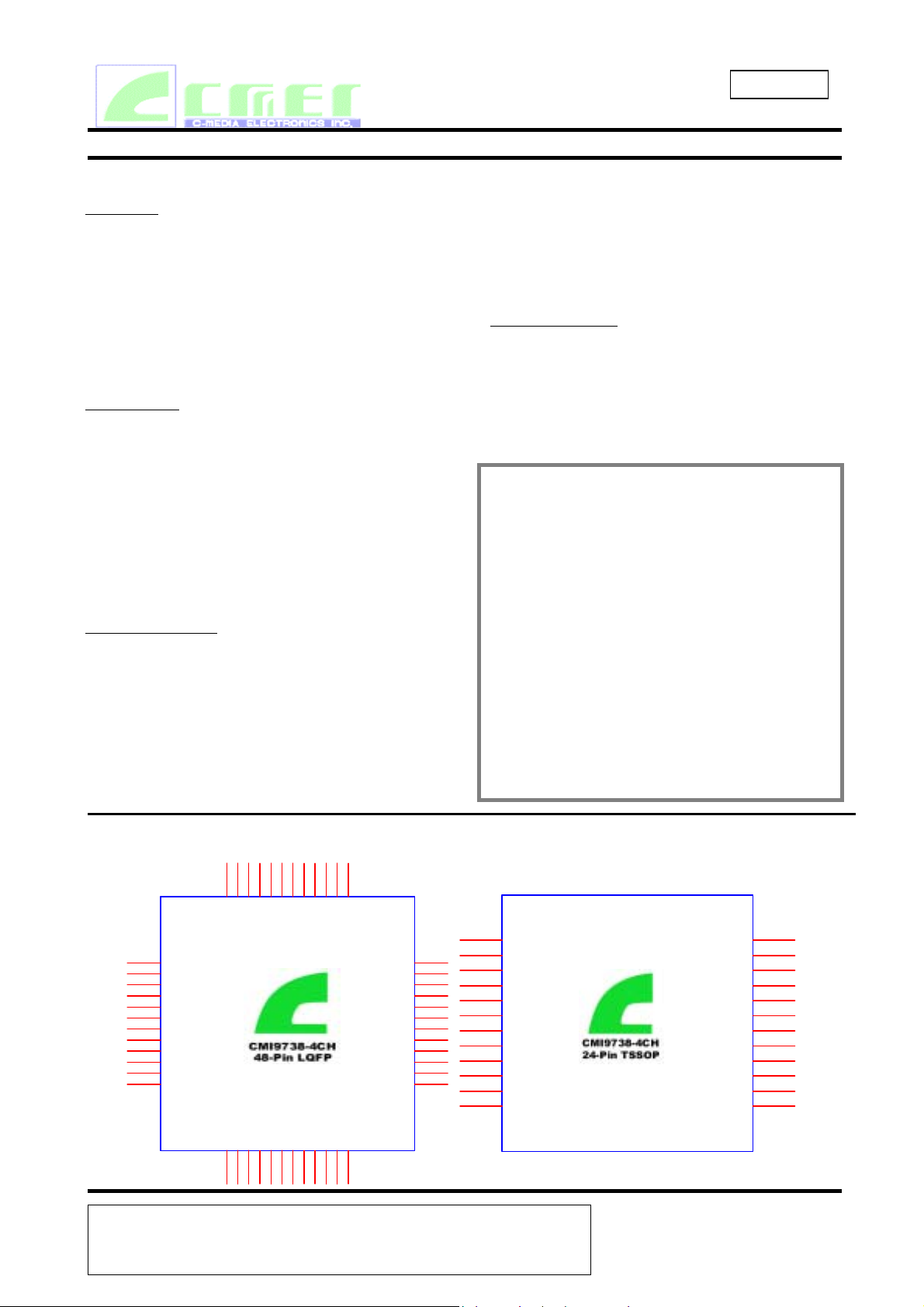
CMI 9738
Integrated Multi-channel AC‘97
CMI9738 4CH Audio Codec Preliminary Specification
1. Description and Overview
Versatility
CMI9738 is a 4CH AC97 CODEC, applicable fo
currently mainstream MB chipsets of Intel, VIA,
li, and SIS. CMI9738 is ideal fo
PC2001-compliant desktops, notebooks, and
home entertainment PCs where high-quality
audio is a must.
4CH Playback
The specially-designed 4CH hardware
architecture of CMI9738 allows all types of south
bridge to playback 4CH audio, thus helping
commonplace south bridge get rid of the
limitation of 2CH audio playback capability
(patent pending both in Taiwan and United
States).
Cost-effectiveness
s to the cost concern, CMI9738 integrates the
earphone buffer, analog CD differential interface,
and analog switch for rear channel audio to
Line-in. Simply by using 0.1uf decoupling
capacitor, CMI9738 meets PC2001 frequency
response requirements.
longside offering standard LQFP 48pin
packaging option, CMI9738 also offers SOP
24pin packaging, which helps to further cut the
cost.
More Audio Option
Last but not least, CMI9738 provides
Sensaura® 3D audio option. In that regard,
the audio quality of CMI9738 is fabulous
beyond general expectation.
Features
Intel AC’97 Rev 2.2 compatible
AC-Link Protocol compliance
Full-Duplex Codec
Earphone Buffer
Line-in/rear out share jack capability
4 channels DAC
48 LQFP Package and 24-Lead TSSOP
Package
Meet Microsoft’s
Sensaura® 3D Enhancement(optional)
PC2001 requirements
Pin Block Diagram
25
26
27
28
29
30
31
32
33
34
35
36
NC
NC
NC
NC
37
NC
38
AVdd2
39
REAR_OUT_L
40
TEST0#
41
REAR_OUT_R
42
AVss2
43
NC
44
NC
45
RESERVED
46
RESERVED
47
NC
48
NC
C-MEDIA Electronics Inc.
LINE_OUT_L
LINE_OUT_R
U2
CMI9738-LQFP-48
DVdd1
XTL_IN
XTL_OUT
DVss1
SDATA_OUT
1234567891011
AFILT1
AFILT2
BIT_CLK
DVss2
SDATA_IN
NC
Vrefout
DVdd2
SYNC
AVdd1
AVss1
LINE_IN_R
LINE_IN_L
CD_GND
AUX_IN_R
AUX_IN_L
RESET#
NC
12
NC
MIC1
CD_R
CD_L
NC
NC
NC
24
23
22
21
20
19
18
17
16
15
14
13
6F, 100, Sec. 4, Civil Boulevard, Taipei, Taiwan, R.O.C. 106
TEL: 886-2-8773-1100 FAX: 886-2-8773-2211 E-mail:sales@cmedia.com.tw
1
SDATA_IN
2
SYNC
3
RESET#
4
AUX_IN_L
5
AUX_IN_R
6
CD_L
7
CD_GND
8
CD_R
9
MIC1
10
LINE_IN_L
11
LINE_IN_R
12 13
VREF_OUT XADCHL
BIT_CLK
SDATA_OUT
XTL_OUT
XTL_IN
DVsdd
TEST0#
LINE_OUT_R
AVdd
LINE_OUT_L
XADCHR
Vss
24
23
22
21
20
19
18
17
16
15
14
Revision Date:Apr./2002
Revision :1.1
Page 2
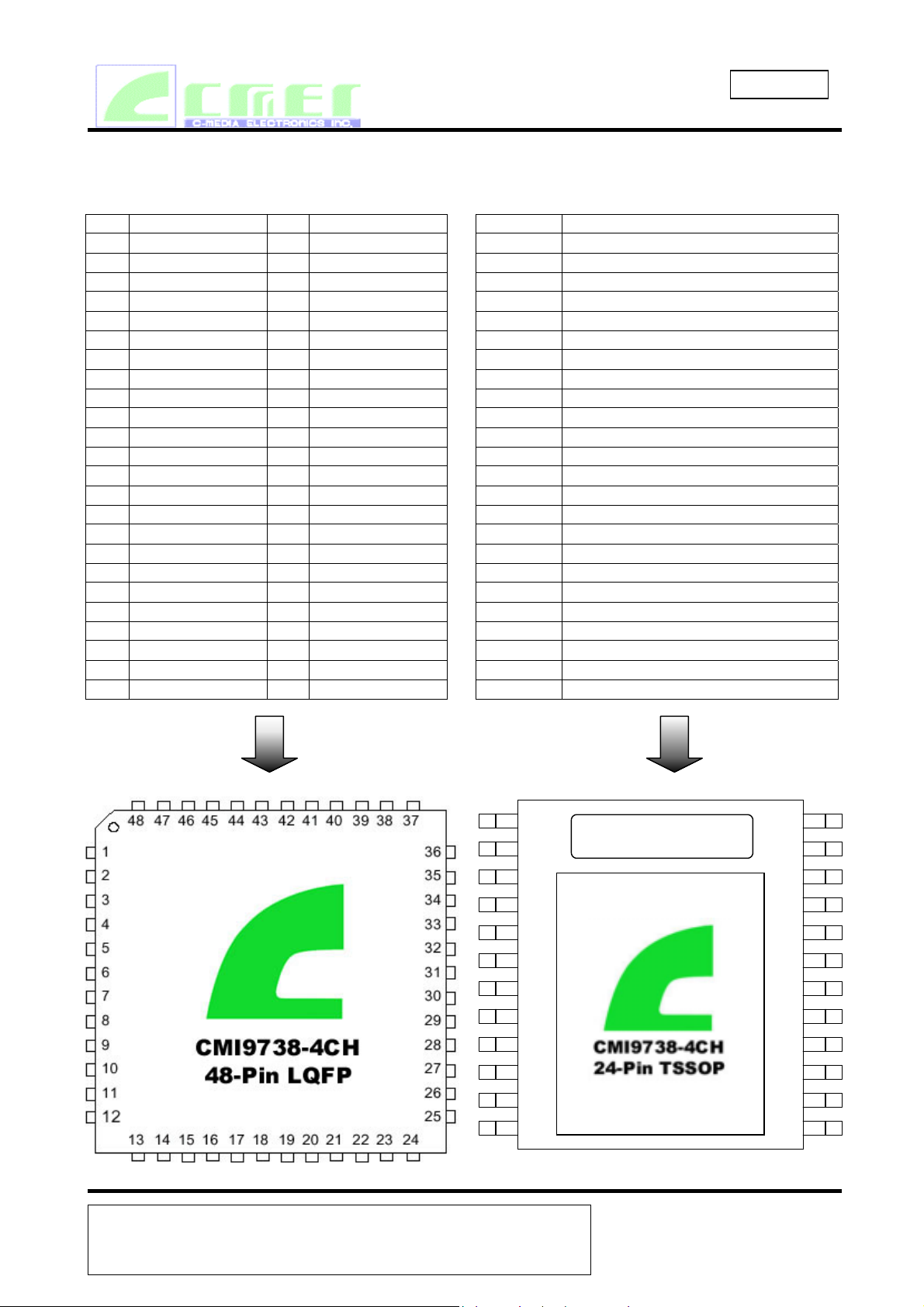
PIN DESCRIPTIONS
48-Pin LQFP 24-Pin TSSOP
PIN # Signal Name PIN # Signal Name
1 DVdd1 25 AVdd1
2 XTL_IN 26 AVss1
3 XTL_OUT 27 NC
4 DVss1 28 Vrefout
5 SDATA_OUT 29 AFILT1
6 BIT_CLK 30 AFILT2
7 DVss2 31 NC
8 SDATA_IN 32 NC
9 DVdd2 33 NC
10 SYNC 34 NC
11 RESET# 35 LINE_OUT_L
12 NC 36 LINE_OUT_R
13 NC 37 NC
14 AUX_IN_L 38 AVdd2
15 AUX_IN_R 39 REAR_OUT_L
16 NC 40 TEST0#
17 NC 41 REAR_OUT_R
18 CD_L 42 AVss2
19 CD_GND 43 NC
20 CD_R 44 NC
21 MIC1 45 RESERVED
22 NC 46 RESERVED
23 LINE_IN_L 47 NC
24 LINE_IN_R 48 NC
PIN # Signal Name
1 SDATA_IN
2 SYNC
3 RESET#
4 AUX_IN_L
5 AUX_IN_R
6 CD_L
7 CD_GND
8 CD_R
9 MIC1
10 LINE_IN_L
11 LINE_IN_R
12 VREF_OUT
13 AFILT1
14 AFILT2
15 LINE_OUT_L
16 LINE_OUT_R
17 AVdd
18 TEST0#
19 Vss
20 DVsdd
21 XTL_IN
22 XTL_OUT
23 SDATA_OUT
24 BIT_CLK
CMI 9738
Integrated Multi-channel AC‘97
1
2
3
4
5
6
7
8
9
10
11
12
24
23
22
21
20
19
18
17
16
15
14
13
C-MEDIA Electronics Inc.
6F, 100, Sec. 4, Civil Boulevard, Taipei, Taiwan, R.O.C.
TEL: 886-2-8773-1100 FAX: 886-2-8773-2211 E-mail:sales@cmedia.com.tw
106
Revision Date:Apr./2002
Revision :1.1
Page 3
CMI 9738
Integrated Multi-channel AC‘97
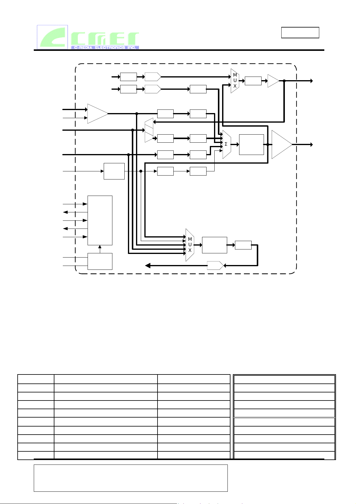
CMI9738 Mixer Block Diagram
REAR OUT
FRONT OUT
SRC
SRC
Mixer Block Diagram
DAC
DAC
MUTE
M
U
X
BufMUTE
39, 41
REAR_OUT_L/R
CD_L/R
CD_GND
LINE_IN_L/
REAR OUT
AUX_INL/R
SYNC
BIT_CLK
DATA_OUT
S
SDATA_IN
RESET#
XTL_IN
XTL_OUT
MIC1
R
18, 20
(6, 8)
23, 24
(10, 11)
14, 15
(4, 5)
(24)
(23)
(21)
(22)
19
(7)
(LINE_IN/REAR_OUT)
21
(9)
10
(2)
6
5
8
(1)
11
(3)
2
3
Noise
Cancel
AC'97
Digital
Interface
OSC
BOOST
(+20dB)
PCM IN
VOL MUTE
M
U
X
VOL MUTE
MUTEVOL
MUTEVOL
M
U
X
Record
Gain
Control
ADC
MASTER
Σ
VOLUME
/ MUTE
MUTE
Earphone
Buffer
XX : LQFP-48
(XX) : SSOP-24
35, 36
(15, 16)
LINE_OUT_L/R
The CMI9738 mixer is designed to the AC’97 specification to manage playback and record
of all digital and analog audio sources in the PC environment. These include:
System audio:digital PCM input and output for business, games, and multimedia
CD/DVD:analog CD/DVD-ROM Redbook audio with internal connections to Codec mixer
Mono microphone:choice of desktop or headset mic, with programmable boost and gain
Speakerphone:use of system mic & speakers for telephony, DSVD, and video
conferencing
Stereo line in:analog external line level source from consumer audio, video camera, etc
AUX/synth:analog FM or wavetable synthesizer, or other internal source
SOURCE FUNCTION CONNECTION OUTPUT MIX SUPPORTS:
MIC1 desktop microphone from mic jack •stereo mix of all sources for LINE_OUT
LINE_IN external audio source from line in jack •stereo output for REAR_OUT
CD audio from CD-ROM drive cable from CD-ROM
AUX upgrade synth or other external source internal connector
PCM out digital audio output from AC '97 Controller AC-link
Mix out mix of all sources AC ‘97 internal •any mono or stereo source
LINE_OUT stereo mix of all sources (front channel) to output jack •mono or stereo mix of all sources
REAR_OUT stereo output of rear (surround) channel to output jack
PCM in digital audio input to AC '97 Controller AC-link
INPUT MUX SUPPORTS:
C-MEDIA Electronics Inc.
6F, 100, Sec. 4, Civil Boulevard, Taipei, Taiwan, R.O.C. 106
TEL: 886-2-8773-1100 FAX: 886-2-8773-2211 E-mail:sales@cmedia.com.tw
Revision Date:Apr./2002
Revision :1.1
Page 4
CMI 9738
Integrated Multi-channel AC‘97
2. ORDERING INFORMATION
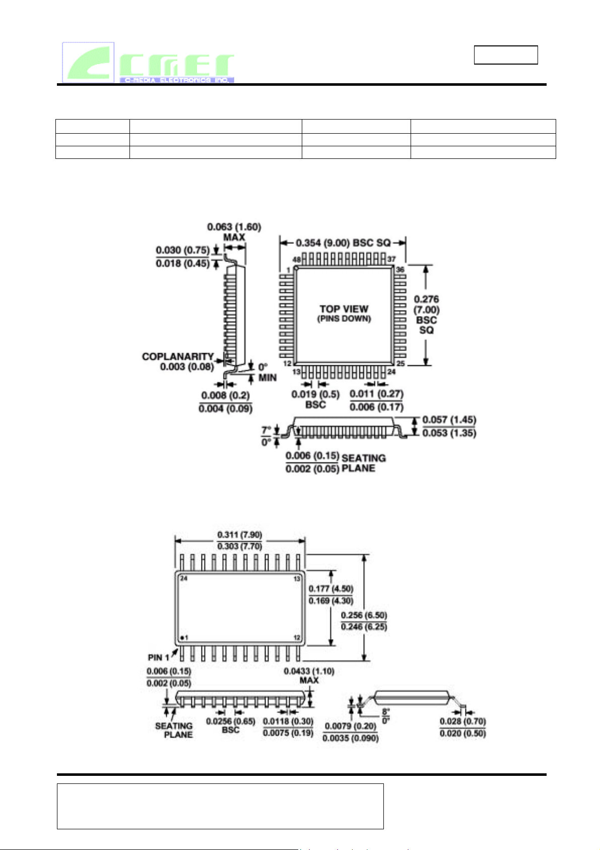
Part Number Package Temperature Range Supply Range
CMI9738 48-Pin LQFP 9mm×7mm×1.6mm 0 o C to +70 o C DVdd = 3.3V, AVdd = 5V
CMI9738 24 Pin-TSSOP 7.9mm×6.5mm×1.1mm 0 o C to +70 o C DVdd = 3.3V, AVdd = 5V
Outline Dimensions
48-Lead Thin Plastic Quad Flatpack (LQFP) (ST-48)
Dimensions shown in inches and (mm)
24-Lead Plastic TSSOP (RU-24)
C-Media reserves the right to change specifications without notice.
C-MEDIA Electronics Inc.
6F, 100, Sec. 4, Civil Boulevard, Taipei, Taiwan, R.O.C. 106
TEL: 886-2-8773-1100 FAX: 886-2-8773-2211 E-mail:sales@cmedia.com.tw
Revision Date:Apr./2002
Revision :1.1
Page 5

CMI 9738
Integrated Multi-channel AC‘97
TABLE OF CONTENTS
1. DESCRIPTION AND OVERVIEW 1
2. ORDERING INFORMATION 4
3. PIN/SIGNAL DESCRIPTIONS 8
3.1 DIGITAL I/O 8
3.1 ANALOG I/O 8
3.2 FILTER AND REFERENCE PINS 8
3.3 POWER AND GROUND SIGNALS 9
4. DIGITAL INTERFACE 10
4.1 AC_LINK 10
4.2 CLOCKING 10
4.3 RESETTING 10
4.4 AC-LINK DIGITAL SERIAL INTERFACE PROTOCOL
4.5 AC-LINK AUDIO INPUT FRAME(SDATA_IN) 12
4.6 AC-LINK AUDIO OUTPUT FRAME(SDATA_OUT) 14
4.7 AC-LINK LOW POWER MODE 17
11
5. CMI9738 MIXER 19
5.1 MIXER INPUT 20
5.2 MIXER OUTPUT 20
6. REGISTER INTERFACE 21
6.1 REGISTER DESCRIPTIONS 22
6.2 PIN DESCRIPTIONS 28
7. AC-LINK TIMING CHARACTERISTICS 29
7.1 COLD RESET 29
7.2 WARM RESET 29
7.3 CLOCKS 29
7.4 DATA SETUP AND HOLD 30
7.5 SIGNAL RISE AND FALL TIMES 31
7.6 AC-LINK LOW POWER MODE TIMING 32
7.7 ATE TEST MODE 32
8. ELECTRICAL SPECIFICATIONS 33
8.1 DC CHARACTERISTICS 33
8.2 ABSOLUTE MAXIMUM RATINGS 33
8.3 RECOMMENDED OPERATING CONDITIONS 34
8.4 MIXER CHARACTERISTICS 34
8.5 POWER CONSUMPTION 35
8.6 ANALOG PERFORMANCE CHARACTERISTICS 35
C-MEDIA Electronics Inc.
6F, 100, Sec. 4, Civil Boulevard, Taipei, Taiwan, R.O.C. 106
TEL: 886-2-8773-1100 FAX: 886-2-8773-2211 E-mail:sales@cmedia.com.tw
Revision Date:Apr./2002
Revision :1.1
Page 6

CMI 9738
Integrated Multi-channel AC‘97
9. REFERENCES 37
10. LIST OF FIGURES
Figure 1. AC ‘97 connection to its companion controller
Figure 2. AC ‘97 Standard Bi-directional Audio Frame
Figure 3. AC-link Audio Input Frame 12
Figure 4. Start of an Audio Input Frame 13
Figure 5. AC-Link Audio Output Frame 14
Figure 6. Start of an Audio Output Frame 15
Figure 7. AC-link Powerdown Timing 17
Figure 8. CMI9738 Mixer Functional Diagram 19
Figure 9. Cold Reset timing diagram 29
Figure 10. Warm Reset 29
Figure 11. BIT_CLK to SYNC timing diagram 30
Figure 12. Data Setup and Hold 30
Figure 13. Signal rise and fall times diagram 31
Figure 14. AC-link low power mode timing diagram
Figure 15. ATE test mode timing diagram 32
11. LIST OF TABLES
Table 1. Digital Signal List 8
10
11
32
Table 2. Analog Signal List 8
Table 3. Filtering and Voltage References 9
Table 4. Power Signal List CMI9738 9
Table 5. Mixer Functional Connections 20
Table 6. Mixer Registers 22
Table 7. Cold Reset timing parameters 28
Table 8 Warm Reset 28
Table 9. Clocks 29
Table 10. Data setup and hold timing parameters
Table 11. Signal rise and fall times parameters 30
Table 12. AC-link low power mode timing parameters
Table 13. ATE test mode timing parameters 31
Table 14. DC Characteristics (relative to Vdd) 32
Table 15. DC Characteristics (3.3 V Operation as per PCI 2.2)
Table 16. Absolute Maximum Ratings 33
Table 17. Operating Conditions 33
Table 18. Mixer Characteristics 33
30
31
32
Table 19. Power Consumption 34
Table 20. Analog performance characteristics 35
C-MEDIA Electronics Inc.
6F, 100, Sec. 4, Civil Boulevard, Taipei, Taiwan, R.O.C. 106
TEL: 886-2-8773-1100 FAX: 886-2-8773-2211 E-mail:sales@cmedia.com.tw
Revision Date:Apr./2002
Revision :1.1
Page 7
CMI 9738
Integrated Multi-channel AC‘97
3. PIN/SIGNAL DESCRIPTIONS
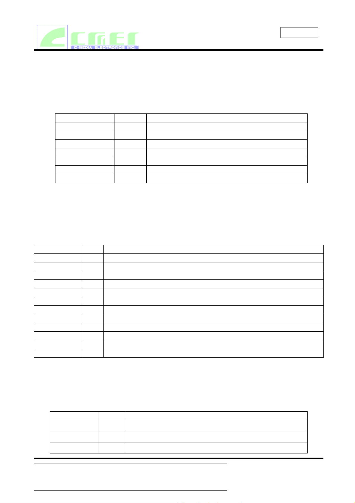
3.1 DIGITAL I/O
These signals connect the CMI9738 to its AC’97 Controller counterpart, an external crystal,
multi-codec selection and external audio amplifier.
Table 1. Digital Signal List
Signal Name Type Description
RESET# I AC’97 Master H/W Reset
XTL_IN I 24.576 MHz Crystal
XTL_OUT O 24.576 MHz Crystal
SYNC I 48 kHz fixed rate sample sync
BIT_CLK O 12.288 MHz serial data clock
SDATA_OUT I Serial, time division multiplexed, AC’97 input stream
SDATA_IN O Serial, time division multiplexed, AC’97 output stream
# denotes active low
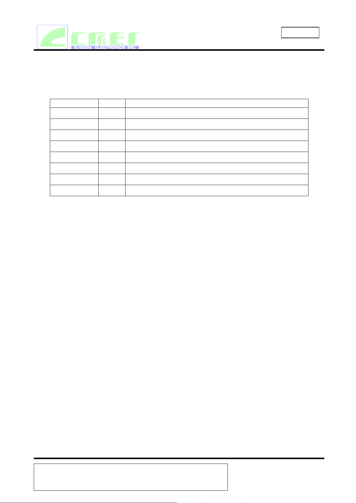
3.2 ANALOG I/O
These signals connect the CMI9738 to analog sources and sinks, including microphones and
speakers.
Table 2. Analog Signal List
Signal Name Type Description
AUX_IN_L I Aux Left Channel
AUX_IN_R I Aux Right Channel
CD_L I CD Audio Left Channel
CD_R I CD Audio Right Channel
CD_GND I CD Audio analog ground
MIC1 I Desktop Microphone Input
LINE_IN_L I Line In Left Channel
LINE_IN_R I Line In Right Channel
LINE_OUT_L O Line Out Left Channel
LINEOUT_R O Line Out Right Channel
REAR_OUT_L O Rear Out Left Channel
REAR_OUT_R O Rear Out Right Channel
3.3 FILTERAND REFERENCE PINS
These signals are connected to resistors, capacitors, or specific voltages, or provide general
purpose I/O.
Table3. Filtering and Voltage References
Signal Name Type Description
Vrefout O Reference Voltage out 5mA drive (intended for mic bias)
AFLIT1 O Anti-Aliasing Filter Cap - ADC channel & Sampling hold
AFLIT2 O Anti-Aliasing Filter Cap - ADC channel & Sampling hold
C-MEDIA Electronics Inc.
6F, 100, Sec. 4, Civil Boulevard, Taipei, Taiwan, R.O.C. 106
TEL: 886-2-8773-1100 FAX: 886-2-8773-2211 E-mail:sales@cmedia.com.tw
Revision Date:Apr./2002
Revision :1.1
Page 8
3.4 POWER AND GROUND SIGNALS
Table4. Power Signal List CMI9738
Signal Name Type Description
AVdd1 I
CMI 9738
Integrated Multi-channel AC‘97
Analog Vdd = 5V
AVdd2 I
Analog Vdd = 5V
Avss1 I Analog Gnd
Avss2 I Analog Gnd
DVdd1 I
DVdd2 I
Digital Vdd = 3.3V
Digital Vdd = 3.3V
DVss1 I Digital Gnd
DVss2 I Digital Gnd
C-MEDIA Electronics Inc.
6F, 100, Sec. 4, Civil Boulevard, Taipei, Taiwan, R.O.C. 106
TEL: 886-2-8773-1100 FAX: 886-2-8773-2211 E-mail:sales@cmedia.com.tw
Revision Date:Apr./2002
Revision :1.1
Page 9
CMI 9738
Integrated Multi-channel AC‘97
4. DIGITAL INTERFACE
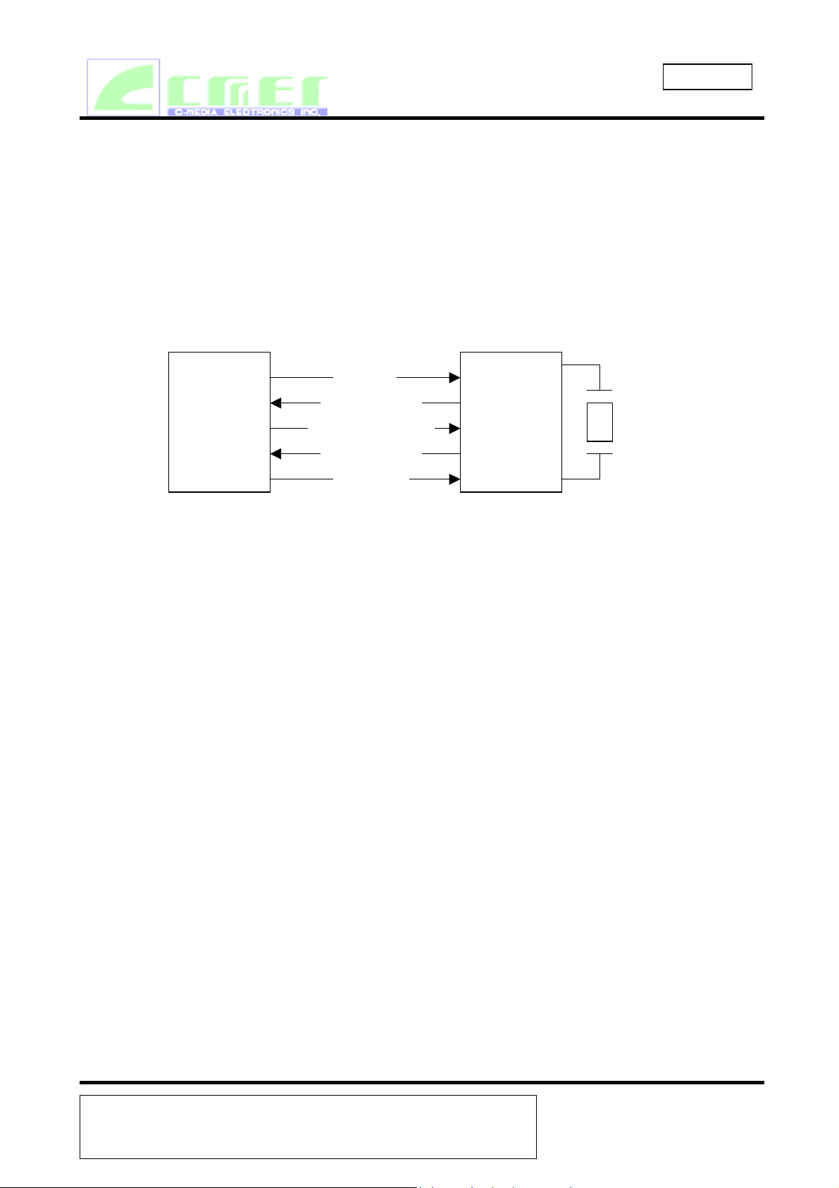
4.1 AC-LINK
All digital audio streams, optional modem line Codec streams, and command/status information
are communicated over this AC-Link. A breakout of the signals connecting the two is shown in
Figure .
Figure1. AC ‘97 connection to its companion controller
Digital
DC’97
Controller
4.2 CLOCKING
SYNC
BIT_CLK
SDTA_OUT
SDATA_IN
RESET#
AC’97
Codec
XTAL_IN
XTAL_OUT
CMI9738 derives its clock internally from an externally connected 24.576 MHz crystal or an
oscillator through the XTAL_IN pin. Synchronization with the AC’97 controler is achieved
through the BIT_CLK pin at 12.288 MHz(half of crystal frequency).
The beginning of all audio sample packets, or Audio Frames, transferred over AC-link is
synchronized to the rising edge of the “SYNC” signal. “SYNC” is driven by the AC ’97
Controller. Data is transitioned on AC-link on everyrising edge of BIT_CLK, and subsequently
sampled on the receiving side of AC-link on each immediately followingfalling edge of
BIT_CLK.
4.3 RESETTING
There are three types of reset as detailed under “Timing Characteristics”:
1. a cold reset where all CMI9738 logic (registers included) is initialized to its default state
2. a warm reset where the contents of the CMI9738 register set are left unaltered
3. a register reset which only initializes the CMI9738 registers to their default states
After signaling a reset to the CMI9738, the AC’97 Controller should not attempt to play or
capture audio data until it has sampled a “Codec Ready” indication via register 26h from the
CMI9738.
Notice:When the AC-link “Codec Ready” indicator bit (SDATA_IN slot 0, bit 15) is a 1 it
indicates that the AC-link and AC ‘97 control and status registers are in a fully
operational state.
C-MEDIA Electronics Inc.
6F, 100, Sec. 4, Civil Boulevard, Taipei, Taiwan, R.O.C. 106
TEL: 886-2-8773-1100 FAX: 886-2-8773-2211 E-mail:sales@cmedia.com.tw
Revision Date:Apr./2002
Revision :1.1
Page 10
CMI 9738
Integrated Multi-channel AC‘97
4.4 AC-LINK DIGITAL SERIAL INTERFACE PROTOCOL
The CMI9738 communicates to the AC'97 controller via a 5-pin digital serial AC-Link
interface,which is a bi-directional, fixed rate, serial PCM digital stream. All digital audio streams,
commandsand status information are communicated over this point-to-point serial interconnect.
The AC-Linkhandles multiple inputs, and output audio streams, as well as control register
accesses using a timedivision multiplexed (TDM) scheme. The AC'97 controller synchronizes all
AC-Link data transaction.The following data streams are available on the CMI9738:
· SDATA_OUT TAG
· SDATA_IN TAG
· Status (STATUS ADDR & DATA) read port
· PCM L & R DAC Playback
· PCM L & R ADC Record
1 output slot (0)
1 input slot (0)
2 input slots (1,2)
2 output slots (3,4)
2 input slots (3,4)
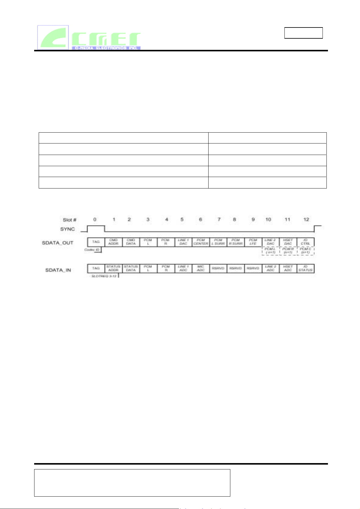
Figure2. AC ‘97 Standard Bi-directional Audio Frame
Synchronization of all AC-Link data transactions is handled by the AC'97 controller. The
CMI9738 drives the serial bit clock onto AC-Link. The AC'97 controller then qualifies with a
synchronization signal to construct audio frames.
SYNC, fixed at 48 kHz, is derived by dividing down the serial bit clock (BIT_CLK). BIT_CLK,
fixed at 12.288 MHz, provides the necessary clocking granularity to support 12, 20-bit outgoing
and incoming time slots. AC-Link serial data is transitioned on each rising edge of BIT_CLK. The
receiver of AC-Link data, CMI9738 for outgoing data and AC'97 controller for incoming data,
samples each serial bit on the falling edges of BIT_CLK.
The AC-Link protocol provides for a special 16-bit (13-bits defined, with 3 reserved trailing bit
positions) time slot (Slot 0) wherein each bit conveys a valid tag for its corresponding time slot
within the current audio frame. A “1” in a given bit position of slot 0 indicates that the
corresponding time slot within the current audio frame has been assigned to a data stream, and
contains valid data. If a slot is “tagged” invalid, it is the responsibility of the source of the data
(CMI9738 for the input stream, AC'97 controller for the output stream) to stuff all bit positions
with 0’s during that slot’sactive time.
C-MEDIA Electronics Inc.
6F, 100, Sec. 4, Civil Boulevard, Taipei, Taiwan, R.O.C. 106
TEL: 886-2-8773-1100 FAX: 886-2-8773-2211 E-mail:sales@cmedia.com.tw
Revision Date:Apr./2002
Revision :1.1
Page 11
CMI 9738
Integrated Multi-channel AC‘97
SYNC remains high for a total duration of 16 BIT_CLKs at the beginning of each audio frame.
Theportion of the audio frame where SYNC is high is defined as the “Tag Phase”. The remainder
of theaudio frame where SYNC is low is defined as the “Data Phase”.
Additionally, for power savings, all clock, sync, and data signals can be halted.
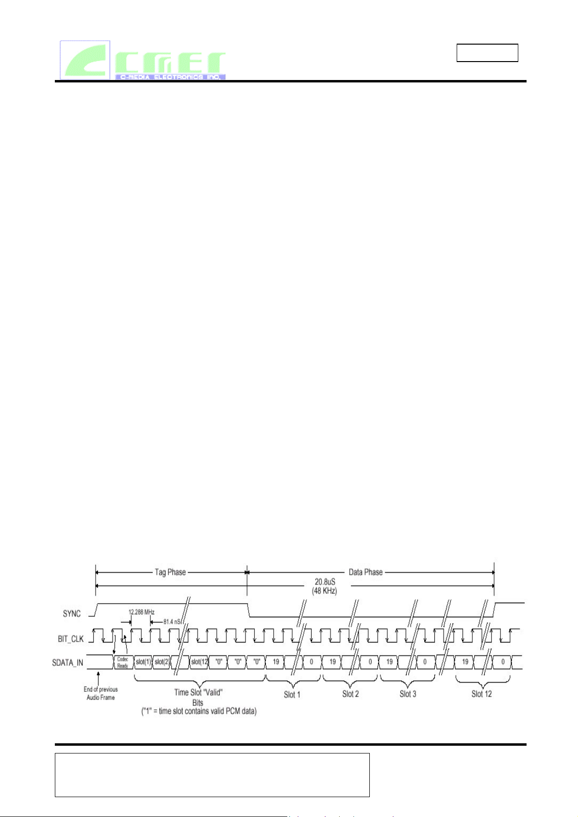
4.5 AC-LINK AUDIO INPUT FRAME(SDATA_IN)
The audio input frame data streams correspond to the multiplexed bundles of all digital input data
targeting the AC’97 Controller. As is the case for audio output frame, each AC-link audio input
frame consists of 12, 20-bit timeslots. Slot 0 is a special reserved time slot containing 16-bits
which are used for AC-link protocol infrastructure.
Within slot 0 the first bit is a global bit (SDATA_IN slot 0, bit 15) which flags whether CMI9738
is in the “CodecReady” state or not. If the “Codec Ready” bit is a 0, this indicates thatCMI9738 is
not ready for normal operation. This condition is normal following the deassertion of power on
reset for example, while CMI9738’s voltage references settle. When the AC-link “Codec Ready”
indicator bit is a 1 it indicates that the AC-link and CMI9738 control and status registers are in a
fully operational state. The AC ‘97 Controller must further probe the Powerdown Control/Status
Register (section 6.3) to determine exactly which subsections, if any, are ready.
Prior to any attempts at putting CMI9738 into operation the AC ’97 Controller should poll the
first bit in the audio input frame (SDATA_IN slot 0, bit 15) for an indication that CMI9738 has
gone “Codec Ready”. Once CMI9738 is sampled “Codec Ready”8 then the next 12 bit positions
sampled by the AC ’97 Controller indicate which of the corresponding 12 time slots are assigned
to input data streams, and that they contain valid data. The following diagram illustrates the time
slot-based AC-link protocol.
Figure3. AC-link Audio Input Frame
C-MEDIA Electronics Inc.
6F, 100, Sec. 4, Civil Boulevard, Taipei, Taiwan, R.O.C. 106
TEL: 886-2-8773-1100 FAX: 886-2-8773-2211 E-mail:sales@cmedia.com.tw
Revision Date:Apr./2002
Revision :1.1
Page 12

CMI 9738
Integrated Multi-channel AC‘97
A new audio input frame begins with a low to high transition of SYNC. SYNC is synchronous to
the rising edge of BIT_CLK. On the immediately following falling edge of BIT_CLK, CMI9738
samples the assertion of SYNC. This falling edge marks the time when both sides of AC-link are
aware of the start of a new audio frame. On the next rising of BIT_CLK, the CMI9738 transitions
SDATA_IN into the first bit position of slot 0 (“Codec Ready” bit). Each new bit position is
presented to AC-link on a rising edge of BIT_CLK, and subsequently sampled by the AC ’97
Controller on the following falling edge of BIT_CLK. This sequence ensures that data transitions
and subsequent sample points for both incoming and outgoing data streams are time aligned.
Figure4. Start of an Audio Input Frame
SDATA_IN's composite stream is MSB justified (MSB first) with all non-valid bit positions (for
assigned and/or unassigned time slots) stuffed with 0's by CMI9738. SDATA_IN data is sampled
on the falling edges of BIT_CLK.
Slot 1: Status Address Port
The status port is used to monitor status for CMI9738 functions including, but not limited to,
mixer settings and power management (refer to section 6.3 of this specification).
Audio input frame slot 1’s stream echoes the control register index, for historical reference, for the
data to be returned in slot 2. (Assuming that slots 1 and 2 had been tagged “valid” by CMI9738
during slot 0.)
Status Address Port bit assignments:
Bit(19)
Bit(18;12)
RESERVED (Stuffed with 0)
Control Register Index (Echo of register index for which data is being returned)
Bit(11:0)
RESERVED (Stuffed with 0’s)
The first bit (MSB) generated by CMI9738 is always stuffed with a 0. The following 7 bit
positions communicate the associated control register address, and the trailing 12 bit positions are
stuffed with 0's by CMI9738.
Slot 2: Status Data Port
The status data port delivers 16-bit control register read data.
C-MEDIA Electronics Inc.
6F, 100, Sec. 4, Civil Boulevard, Taipei, Taiwan, R.O.C. 106
TEL: 886-2-8773-1100 FAX: 886-2-8773-2211 E-mail:sales@cmedia.com.tw
Revision Date:Apr./2002
Revision :1.1
Page 13

CMI 9738
Integrated Multi-channel AC‘97
Bit(19:4)
Bit(3:0)
Control Register Read Data (Stuffed with 0’s if tagged “invalid”)
RESERVED (Stuffed with 0’s)
If Slot 2 is tagged invalid by CMI9738, then the entire slot will be stuffed with 0’s.
Slot 3: PCM Record Left Channel
Audio input frame slot 3 is the left channel output of CMI9738 input MUX, post-ADC.
CMI9738 ADCs are implemented to support 18-bit resolution.
CMI9738 outputs its ADC data (MSB first), and stuffs any trailing non-valid bit positions
with 0's to fill out its 20-bit time slot.
Slot 4: PCM Record Right Channel
Audio input frame slot 4 is the right channel output of CMI9738 input MUX, post-ADC.
CMI9738 outputs its ADC data (MSB first), and stuffs any trailing non-valid bit positions
with 0's to fill out its 20-bit time slot.
Slot 5: Optional Modem Line 1 ADC
Audio input frame slots 5-12 are not used by the CMI9738 and are always stuffed with 0's.
4.6 AC-LINK AUDIO OUTPUT FRAME(SDATA_OUT)
The audio output frame data streams correspond to the multiplexed bundles of all digital output
data targeting the CMI9738 DAC inputs, and control registers. Each audio output frame supports
up to 12 20-bit outgoing data time slots. Slot 0 is a special reserved time slot containing 16 bits
that are used for AC-Link protocol infrastructure.
Within slot 0, the first bit is a global bit (SDATA_OUT slot 0, bit 15) which flags the validity for
the entire audio frame. If the “Valid Frame” bit is a 1, this indicates that the current audio frame
contains at least one slot time of valid data. The next 12 bit positions sampled by the CMI9738
indicate which of the corresponding 12 times slots contain valid data. In this way data streams of
differing sample rates can be transmitted across AC-Link at its fixed 48kHz audio frame rate. The
following diagram illustrates the time slot based AC-Link protocol.
Figure5 . AC-Link Audio Output Frame
C-MEDIA Electronics Inc.
6F, 100, Sec. 4, Civil Boulevard, Taipei, Taiwan, R.O.C. 106
TEL: 886-2-8773-1100 FAX: 886-2-8773-2211 E-mail:sales@cmedia.com.tw
Revision Date:Apr./2002
Revision :1.1
Page 14

CMI 9738
Integrated Multi-channel AC‘97
A new audio output frame begins with a low to high transition of SYNC. SYNC is synchronous to
the rising edge of BIT_CLK. On the immediately following falling edge of BIT_CLK, the
CMI9738 samples the assertion of SYNC. This following edge marks the time when both sides of
AC-Link are aware of the start of a new audio frame. On the next rising edge of BIT_CLK, the
AC'97 controller transitions SDATA_OUT into the first bit position of slot 0 (Valid Frame bit).
Each new bit position is presented to AC-Link on a rising edge of BIT_CLK, and subsequently
sampled by the CMI9738 on the following falling edge of BIT_CLK. This sequence ensures that
data transitions, and subsequent sample points for both incoming and outgoing data streams are
time aligned.
Figure 6. Start of an Audio Output Frame
SDATA_OUT’s composite stream is MSB justified (MSB first) with all non-valid slots’ bit
positions AC'97 controller. When mono audio sample streams are sent from the AC'97 controller
it is necessary that BOTH left and right sample stream time slots be filled with the same data.
Slot 1: Command Address Port
The command port is used to control features, and monitor status (see Audio Input Frame Slots 1
and 2) of the CMI9738 functions including, but not limited to, mixer settings, and power
management (refer to the control register section of this specification).
The control interface architecture supports up to 64 16-bit read/write registers, addressable on
even byte boundaries. Only the even registers (00h, 02h, etc.) are valid.
Audio output frame slot 1 communicates control register address, and write/read command
information to the CMI9738.
Command Address Port bit assignments:
Bit(19)
Bit(18:12)
Bit(11:0)
Read/Write command (1=read, 0=write)
Control Register Index (64 16-bit locations, addressed on even byte boundaries)
Reserved (Stuffed with 0’s)
C-MEDIA Electronics Inc.
6F, 100, Sec. 4, Civil Boulevard, Taipei, Taiwan, R.O.C. 106
TEL: 886-2-8773-1100 FAX: 886-2-8773-2211 E-mail:sales@cmedia.com.tw
Revision Date:Apr./2002
Revision :1.1
Page 15

CMI 9738
Integrated Multi-channel AC‘97
The first bit (MSB) sampled by CMI9738 indicates whether the current control transaction is a
read or a write operation. The following 7 bit positions communicate the targeted control register
address. The trailing 12 bit positions within the slot are reserved and mu st be stuffed with 0’s by
the AC ’97 Controller.
Slot 2: Command Data Port
The command data port is used to deliver 16-bit control register write data in the event that the
current command port operation is a write cycle. (as indicated by Slot 1, bit 19)
Bit(19:4)
Bit(3:0)
Control Register Write Data (Stuffed with 0's if current operation is a read)
Reserved (Stuffed with 0's)
If the current command port operation is a read then the entire slot time must be stuffed with 0's
by the AC'97 controller.
Slot 3: PCM Playback Left Channel
“Games Compatible" PC this slot is composed of standard PCM (.wav) output samples digitally
mixed (by the AC'97 controller or host processor) with music synthesis output samples. If a
sample stream of resolution less than 20-bits is transferred, the AC'97 controller must stuff all
trailing non-valid bit positions within this time slot with 0's.
Slot 4: PCM Playback Right Channel
Audio output frame slot 4 is the composite digital audio right playback stream. In a typical
“Games Compatible" PC this slot is composed of standard PCM (.wav) output samples digitally
mixed (by the AC'97 controller or host processor) with music synthesis output samples. If a
sample stream of resolution less than 20-bits is transferred, the AC'97 controller must stuff all
trailing non-valid bit positions within this time slot with 0's.
Slot 5: Reserved
Audio output frame slot 5 is reserved for modem operation and is not used by the CMI9738.
Slot 6: PCM Center Channel
Audio output frame slot 6 is not used by the CMI9738.
Slot 7: PCM Left Surround Channel
Slot 7 carries PCM left surround data in 4 channel wave output.
Slot 8: PCM Right Surround Channel
Slot 8 carries PCM right surround data in 4 channel wave output.
Slot 9: PCM Low Frequency Channel
Audio output frame slot 9 is not used by the CMI9738.
Slot 10: PCM Alternate Left
Audio output frame slot 10 is not used by the CMI9738.
Slot 11: PCM Alternate Right
Audio output frame slot 11 is not used by the CMI9738.
Slot 12: Reserved
C-MEDIA Electronics Inc.
6F, 100, Sec. 4, Civil Boulevard, Taipei, Taiwan, R.O.C. 106
TEL: 886-2-8773-1100 FAX: 886-2-8773-2211 E-mail:sales@cmedia.com.tw
Revision Date:Apr./2002
Revision :1.1
Page 16

CMI 9738
Integrated Multi-channel AC‘97
Audio output frame slot 12 is reserved for modem operations and is not used by the CMI9738.
4.7 AC-LINK LOW POWER MODE
The CMI9738 AC-Link can be placed in the low power mode by programming register 26h to the
appropriate value. Both BIT_CLK and SDATA_IN will be brought to, and held at a logic low
voltage level. The AC'97 controller can wake up the CMI9738 by providing the appropriate reset
signals.
Figure 7. AC-link Powerdown Timing
BIT_CLK and SDATA_IN are transitioned low immediately (within the maximum s pecified time)
following the decode of the write to the Powerdown Register (26h) with PR4. When the AC'97
controller driver is at the point where it is ready to program the AC-Link into its low power mode,
slots (1 and 2) are assumed to be the only valid stream in the audio output frame (all sources of
audio input have been neutralized).
The AC'97 controller should also drive SYNC and SDATA_OUT low after programming the
CMI9738 to this low power mode.
Waking up the AC-link
Once the CMI9738 has halted BIT_CLK, there are only two ways to “wake up” the AC-Link.
Both methods must be activated by the AC'97 controller. The AC-Link protocol provides for a
“Cold AC'97 Reset”, and a “Warm AC'97 Reset”. The current power down state would ultimately
dictate which form of reset is appropriate. Unless a “cold” or “register” reset (a write to the Reset
register) is performed, wherein the AC'97 registers are initialized to their default values, registers
are required to keep state during all power down modes. Once powered down, re-activation of the
AC-Link via re- assertion of the SYNC signal must not occur for a minimum of 4 audio frame
times following the frame in which the power down was triggered. When AC-Link powers up it
indicates readiness via the Codec Ready bit (input slot 0, bit 15).
C-MEDIA Electronics Inc.
6F, 100, Sec. 4, Civil Boulevard, Taipei, Taiwan, R.O.C. 106
TEL: 886-2-8773-1100 FAX: 886-2-8773-2211 E-mail:sales@cmedia.com.tw
Revision Date:Apr./2002
Revision :1.1
Page 17

CMI 9738
Integrated Multi-channel AC‘97
Cold AC ‘97 Reset Î a cold reset is achieved by asserting RESET# for the minimum specified
time. By driving RESET# low, BIT_CLK, and SDATA_IN will be
activated, or re-activated as the case may be, and all CMI9738 control
registers will be initialized to their default power on reset values.
Note: RESET# is an asynchronous input. # denotes active low
Warm AC’97 Reset Îa warm reset will re-activate the AC-Link without altering the current
CMI9738 register values. A warm reset is signaled by driving SYNC high
for a minimum of 1us in the absence of BIT_CLK.
Note: Within normal audio frames, SYNC is a synchronous input. However, in the absence of
BIT_CLK, SYNC is treated as an asynchronous input used in the generation of a warm reset
to the CMI9738.
C-MEDIA Electronics Inc.
6F, 100, Sec. 4, Civil Boulevard, Taipei, Taiwan, R.O.C. 106
TEL: 886-2-8773-1100 FAX: 886-2-8773-2211 E-mail:sales@cmedia.com.tw
Revision Date:Apr./2002
Revision :1.1
Page 18

CMI 9738
Integrated Multi-channel AC‘97
5. CMI9738 MIXER
The CMI9738 mixer is designed to the AC’97 specification to manage playback and record of all
digital and analog audio sources in the PC environment. These include:
System audio:digital PCM input and output for business, games, and multimedia
CD/DVD:analog CD/DVD-ROM Redbook audio with internal connections to Codec mixer
Mono microphone:choice of desktop or headset mic, with programmable boost and gain
Speakerphone:use of system mic & speakers for telephony, DSVD, and video conferencing
Stereo line in:analog external line level source from consumer audio, video camera, etc
AUX/synth:analog FM or wavetable synthesizer, or other internal source
Figure 8. CMI9738 Mixer Functional Diagram
CD_L/R
CD_GND
LINE_IN_L/R
REAR OUT
AUX_INL/R
MIC1
SYNC
BIT_CLK
SDATA_OUT
SDATA_IN
RESET#
XTL_IN
XTL_OUT
18, 20
(6, 8)
23, 24
(10, 11)
14, 15
(4, 5)
(24)
(23)
(21)
(22)
19
(7)
(LINE_IN/REAR_OUT)
21
(9)
10
(2)
6
5
8
(1)
11
(3)
2
3
REAR OUT
FRONT OUT
Noise
Cancel
AC'97
Digital
Interface
OSC
BOOST
(+20dB)
SRC
SRC
PCM IN
Mixer Block Diagram
DAC
DAC
VOL MUTE
M
U
X
VOL MUTE
MUTE
MUTEVOL
MUTEVOL
M
U
X
Record
Gain
Control
ADC
M
U
X
MASTER
Σ
VOLUME
/ MUTE
MUTE
BufMUTE
Earphone
Buffer
XX : LQFP-48
(XX) : SSOP-24
39, 41
35, 36
(15, 16)
REAR_OUT_L/R
LINE_OUT_L/R
C-MEDIA Electronics Inc.
6F, 100, Sec. 4, Civil Boulevard, Taipei, Taiwan, R.O.C. 106
TEL: 886-2-8773-1100 FAX: 886-2-8773-2211 E-mail:sales@cmedia.com.tw
Revision Date:Apr./2002
Revision :1.1
Page 19

CMI 9738
Integrated Multi-channel AC‘97
Table 5. Mixer Functional Connections
SOURCE FUNCTION CONNECTION
MIC1 desktop microphone from mic jack
LINE_IN external audio source from line in jack
CD audio from CD-ROM drive cable from CD-ROM
AUX upgrade synth or other external source internal connector
PCM out digital audio output from AC '97 Controller AC-link
Mix out mix of all sources AC ‘97 internal
LINE_OUT stereo mix of all sources (also front channel) to output jack
REAR_OUT stereo output of rear (surround) channel to output jack
PCM in digital audio input to AC '97 Controller AC-link
OUTPUT MIX SUPPORTS: INPUT MUX SUPPORTS:
•stereo mix of all sources for LINE_OUT
•stereo output for REAR_OUT
•any mono or stereo source
•mono or stereo mix of all sources
5.1 MIXER INPUT
The CMI9738’s mixer input is a MUX design which offers the capability to record audio sources or
the outgoing mix of all sources. This design is more efficient to implement than an independent
input mix, and offers simple monitoring when a mix is recorded: what you hear is what you get
(WYHIWYG). The CMI9738 supports the following input sources:
any mono or stereo source
mono or stereo mix of all sources
5.2 MIXER OUTPUT
The mixer generates two distinct outputs:
a stereo mix of all sources for output to the LINE_OUT
a stereo output of rear (surround) channel for REAR_OUT
C-MEDIA Electronics Inc.
6F, 100, Sec. 4, Civil Boulevard, Taipei, Taiwan, R.O.C. 106
TEL: 886-2-8773-1100 FAX: 886-2-8773-2211 E-mail:sales@cmedia.com.tw
Revision Date:Apr./2002
Revision :1.1
Page 20

6. REGISTER INTERFACE
CMI 9738
Integrated Multi-channel AC‘97
Table 6. Mixer Registers
Reg
NUM
Reset
00h
Master Volume
02h
Surround Mixer
04h
Volume
Mic Volume
0Eh
LineIn Volume
10h
CD Volume
12h
Aux Volume
16h
PCM Out Vol
18h
Record Select
1Ah
Record Gain
1Ch
General Purpose
20h
Powerdown
26h
Ctrl/Stat
Extended Audio
28h
ID
Ext’d audio
2Ah
Stat/Ctrl
4CH Vol:L,R Surr
38h
Vendor defined
5Ah
Control
Vendor ID1
7Ch
Vendor ID2
7Eh
Name D15 D14 D13 D12 D11 D10 D9 D8 D7 D6 D5 D4 D3 D2 D1 D0 Default
X SE4 SE3 SE2 SE1 SE0 ID9 ID8 ID7 ID6 ID5 ID4 ID3 ID2 ID1 ID0 0000h
Mute X X ML4 ML3 ML2 ML1 ML0 X X X MR4 MR3 MR2 MR1 MR0 0000h
Mute X X ML4 ML3 ML2 ML1 ML0 X X X MR4 MR3 MR2 MR1 MR0 8000h
Mute X X X X X X X X 20dB X X GN3 GN2 GN1 GN0 8008h
Mute X X X GL3 GL2 GL1 GL0 X X X X GR3 GR2 GR1 GR0 8808h
Mute X X X GL3 GL2 GL1 GL0 X X X X GR3 GR2 GR1 GR0 8808h
Mute X X X GL3 GL2 GL1 GL0 X X X X GR3 GR2 GR1 GR0 8808h
Mute X X X GL3 GL2 GL1 GL0 X X X X GR3 GR2 GR1 GR0 8808h
X X X X X SL2 SL1 SL0 X X X X X SR2 SR1 SR0 0000h
Mute X X X GL3 GL2 GL1 GL0 X X X X GR3 GR2 GR1 GR0 8000h
X X X X X X X X LPBK X X X X X X X 0000h
X PR6 PR5 PR4 PR3 PR2 PR1 PR0 X X X X REF ANL DAC ADC 000Xh
ID1 ID0 X X X X X X
X X X PRJ X X X X
Mute X X LSR4 LSR3 LSR2 LSR1 LSR0 Mute X X
X X F2R X X
F7 F6 F5 F4 F3 F2 F1 F0 S7 S6 S5 S4 S3 S2 S1 S0 434Dh
T7 T6 T5 T4 T3 T2 T1 T0 REV7 REV6 REV5 REV4 REV3 REV2 REV1 REV0 4941h
S2LN
I
X X X X X X X X X X 0000h
SDA
X X X X X X X 0080h
C
SDA
X X X X X X X 1000h
C
RSR4 RSR3 RSR2 RSR1 RSR
8080h
0
C-MEDIA Electronics Inc.
6F, 100, Sec. 4, Civil Boulevard, Taipei, Taiwan, R.O.C. 106
TEL: 886-2-8773-1100 FAX: 886-2-8773-2211 E-mail:sales@cmedia.com.tw
Revision Date:Apr./2002
Revision :1.1
Page 21

CMI 9738
Integrated Multi-channel AC‘97
6.1 Register Descriptions
Reset Register (Index 00h) (Read Only)
Reg Name D15 D14 D13 D12 D11 D10 D9 D8 D7 D6 D5 D4 D3 D2 D1 D0 Default
00h Reset
X SE4 SE3 SE2 SE1 SE0 ID9 ID8 ID7 ID6 ID5 ID4 ID3 ID2 ID1 ID0 0000h
No Hardware 3D : SE4…SE0 = 00000b
16 bit ADC & DAC : ID9…ID0 = 0000000000b
Writing this register will reset the mixer register.
Master Volume Registers (Index 02h, 04h and 06h)
Reg Name D15 D14 D13 D12 D11 D10 D9 D8 D7 D6 D5 D4 D3 D2 D1 D0 Default
02h Master Volume
Surround
04h
Mixer Volume
Mut
X X
e
Mut
X X X X X X X X X X X X X X 1 X 8000h
e
ML4 ML3 ML2 ML1 ML
0
X X X
MR4 MR3 MR2 MR1 MR
0000h
0
Each step corresponds to 1.5 dB. The MSB of the register is the mute bit. When this bit is set to 1
the level for that channel is set at -∞ dB.
Support for the MSB of the level is optional. If the MSB is not supported then AC ‘97 needs to
detect when that bit is set and set all four LSBs to 1s. Example: If AC ‘97 only supports 5 bits of
resolution in its mixer and the driver writes a 1xxxxx AC ‘97 must interpret that as x11111. It w il l
also respond when read with x11111 rather
then 1xxxxx, the value writen to it. The driver can use this feature to detect if support for the 6th
bit is there or not. The 02h default value is 0000h (0000 0000 0000 0000) , which corresponds to
+12 dB gain with mute off.
Mute Mx5...Mx0 Function
0 000000 +12 dB gain
0 000001 +10.5 dB gain
0 001000 0 dB Attenuation
0 011110 33.0dB Attenuation
0 011111 46.5dB Attenuation
0 111111 46.5dB Attenuation
1 xxxxxx ∞ dB Attenuation
C-MEDIA Electronics Inc.
6F, 100, Sec. 4, Civil Boulevard, Taipei, Taiwan, R.O.C. 106
TEL: 886-2-8773-1100 FAX: 886-2-8773-2211 E-mail:sales@cmedia.com.tw
Revision Date:Apr./2002
Revision :1.1
Page 22

CMI 9738
Integrated Multi-channel AC‘97
Analog Mixer Input Gain Registers (Index 0Eh - 18h) (R/W)
Reg Name D15 D14 D13 D12 D11 D10 D9 D8 D7 D6 D5 D4 D3 D2 D1 D0 Default
0Eh Mic Volume
10h
12h CD Volume
16h Aux Volume
18h
LineIn
Volume
PCM Out
Vol
Mute X X X RM3 RM2 RM1 RM0 X 20dB X X GN3 GN2 GN1 GN0 8008h
Mute X X X GL3 GL2 GL1 GL0 X X X X GR3 GR2 GR1 GR0 8808h
Mute X X X GL3 GL2 GL1 GL0 X X X X GR3 GR2 GR1 GR0 8808h
Mute X X X GL3 GL2 GL1 GL0 X X X X GR3 GR2 GR1 GR0 8808h
Mute X X X GL3 GL2 GL1 GL0 X X X X GR3 GR2 GR1 GR0 8808h
The MSB of the register is the mute bit. When this bit is set to 1 the level for that channel is set at
-∞ dB.
Register 0Eh (Mic Volume Register) has an extra bit that is for a 20 dB boost. When bit 6 is set to 1
the 20 dB boost is on. The default value is 8008, which corresponds to 0 dB gain with mute on.
Mute Mx3...Mx0 Function
0 0000 0 dB Attenuation
0 0001 2dB Attenuation
0 1111 32dB Attenuation
1 xxxx
∞ dB Attenuation
Record Select Control Register (Index 1Ah) (R/W)
Reg Name D15 D14 D13 D12 D11 D10 D9 D8 D7 D6 D5 D4 D3 D2 D1 D0 Default
1Ah Record Select
X X X X X SL2 SL1 SL0 X X X X X SR2 SR1 SR0 0000h
The default value is 0000h, which corresponds to Mic in.
SR2...SR0 Right Record Source
0 Mic
1 CD In (R)
2 N/A
3 Aux In (R)
4 Line In (R)
5 Stereo Mix (R)
6 Mono Mix
7 N/A
SL2...SL0 Left Record Source
0 Mic
1 CD In (L)
2 N/A
3 Aux In (L)
4 Line In (L)
5 Stereo Mix (L)
6 Mono Mix
7 N/A
C-MEDIA Electronics Inc.
6F, 100, Sec. 4, Civil Boulevard, Taipei, Taiwan, R.O.C. 106
TEL: 886-2-8773-1100 FAX: 886-2-8773-2211 E-mail:sales@cmedia.com.tw
Revision Date:Apr./2002
Revision :1.1
Page 23

CMI 9738
Integrated Multi-channel AC‘97
Record Gain Registers (Index 1Ch) (R/W)
Reg Name D15 D14 D13 D12 D11 D10 D9 D8 D7 D6 D5 D4 D3 D2 D1 D0 Default 1Ch Record Gain
Mute X X X GL3 GL2 GL1 GL0 X X X X GR3 GR2 GR1 GR0 8000h
Each step corresponds to 1.5 dB. 22.5dB corresponds to 0F0Fh and 000Fh respectively. The MSB
of the register is the mute bit. When this bit is set to 1 the level for that channel(s) is set at -∞ dB.
The default value is 8000h, which corresponds
to 0 dB gain with mute on.
Mute Gx3...Gx0 Function
0 1111 +22.5 dB gain
0 0000 0 dB gain
1 xxxxx −∞ dB gain
General Purpose Register (Index 20h) (R/W)
Reg Name D15 D14 D13 D12 D11 D10 D9 D8 D7 D6 D5 D4 D3 D2 D1 D0 Default 20h General Purpose
X X X X X X X X LPBK X X X X X X X 0000h
Bit Function
LPBK ADC/DAC loopback mode
Powerdown Control/Status Register (Index 26h) (R/W)
Reg Name D15 D14 D13 D12 D11 D10 D9 D8 D7 D6 D5 D4 D3 D2 D1 D0
26h
Powerdown
Ctrl/Stat
X PR6 PR5 PR4 PR3 PR2 PR1 PR0 X X X X REF ANL DAC ADC 000Xh
Defaul
t
This read/write register is used to program powerdown states and monitor subsystem readiness.
The lower half of this register is read only status, a 1 indicating that the subsection is “ready”.
Ready is defined as the subsection able to perform in its nominal state. When this register is written
the bit values that come in on AC-link will have no effect on read only bits 0-7.
When the AC-link “Codec Ready” indicator bit (SDATA_IN slot 0, bit 15) is a 1 it indicates that the
AC-link and AC ‘97 control and status registers are in a fully operational state. The AC ‘97
Controller must further probe this Powerdown Control/Status Register to determine exactly which
subsections, if any, are ready.
C-MEDIA Electronics Inc.
6F, 100, Sec. 4, Civil Boulevard, Taipei, Taiwan, R.O.C. 106
TEL: 886-2-8773-1100 FAX: 886-2-8773-2211 E-mail:sales@cmedia.com.tw
Revision Date:Apr./2002
Revision :1.1
Page 24

CMI 9738
Integrated Multi-channel AC‘97
Bit Function
X Reserved
REF Vref’s up to nominal level
ANL Analog mixers, etc. ready
DAC DAC section ready to accept data
ADC ADC section ready to transmit data
These bits are pseudo. Default are ready and controlled by PRX.
Bit Function
PR0 PCM in ADC’s & Input Mux Powerdown
PR1 PCM out DACs Powerdown
PR2 Analog Mixer powerdown (Vref still on)
PR3 Analog Mixer powerdown (Vref off)
PR4
PR5 Internal Clk disable
Digital Interface (AC-link) powerdown
(external clk off)
PR6 HP amp powerdown
Except PR4, other bits are pseudo.
When set, corresponding bits will be not ready.
Ex. PR1 =1 causes DAC=0.
PRXX must set the volume to mute!!
PR4 when set will shut down the ACLINK.
Extended Audio ID Register (Index 28h) (Read Only)
Reg Name D15 D14 D13 D12 D11 D10 D9 D8 D7 D6 D5 D4 D3 D2 D1 D0 Default
28h Extended Audio ID
ID1 ID0 X X X X X X SDAC X X X X X X X 0080h
SDAC=1 indicates optional PCM Surround DAC is supported D15,D14:ID1,ID0 is always “00”.
Extended Audio Status and Control Register (Index 2Ah)
Reg Name D15 D14 D13 D12 D11 D10 D9 D8 D7 D6 D5 D4 D3 D2 D1 D0 Default
2Ah
Ext’d audio
Stat/Ctrl
X X X PRJ X X X X SDAC X X X X X X X 1000h
Bits D7 is read only status of the extended audio feature readiness
SDAC=1 indicates the PCM Surround DACs are ready (4CH mode)
Bits D12 are read/write controls of the extended audio feature powerdown
C-MEDIA Electronics Inc.
6F, 100, Sec. 4, Civil Boulevard, Taipei, Taiwan, R.O.C. 106
TEL: 886-2-8773-1100 FAX: 886-2-8773-2211 E-mail:sales@cmedia.com.tw
Revision Date:Apr./2002
Revision :1.1
Page 25

CMI 9738
Integrated Multi-channel AC‘97
PRJ=1 turns the PCM Surround DACs off (4CH mode)
The default value after cold or warm register reset for this register (xxxxh) is all extended features
disabled (D3-D0=0) and powered down (D12=1). The feature readiness status should always be
accurate (D7=x).
These bits are pseudo.
When 2Ch, 4CH, these bits are still visible.
PRXX must set volume to mute
4-Channel Volume Control Register (Index 38h) (R/W)
Reg Name D15
4CH
38h
Vol:L,R
Surr
These read/write registers control the output volume of the optional four PCM channels, and values
written to the fields behave the same as the Play Master Volume Register (Index 02h), which offers
attenuation but no gain. There is an independent mute (1=on) for each channel.
D14 D1
Mute X X LSR4 LSR3 LSR2 LSR1 LSR0 Mute X X RSR4 RSR3 RSR2 RSR1 RSR0 8080h
D12 D11 D10 D9 D8 D7 D6 D5 D4 D3 D2 D1 D0 Default
3
The default value after cold or warm register reset for this register (8080h) corresponds to 0 dB
attenuation with mute on.
When 2/4 CH, these registers are still visible and controllable.
The all bits of the reg38h are pseudo.
Vendor Defined Register (Index 5Ah) (R/W)
Reg Name D15 D14 D13 D12 D11 D10 D9 D8 D7 D6 D5 D4 D3 D2 D1 D0 Default
Vendor
5Ah
defined
Control
X X F2R X X S2LNI X X X X X X X X X X 0000h
S2LNI:Surround to Line in selection.
“0”:disable (default)
“1”:enable
F2R:Front channels are routed to rear channels.
“0”:disable (default)
“1”:enable
C-MEDIA Electronics Inc.
6F, 100, Sec. 4, Civil Boulevard, Taipei, Taiwan, R.O.C. 106
TEL: 886-2-8773-1100 FAX: 886-2-8773-2211 E-mail:sales@cmedia.com.tw
Revision Date:Apr./2002
Revision :1.1
Page 26

CMI 9738
Integrated Multi-channel AC‘97
Vendor ID Registers (Index 7Ch - 7Eh) (Read Only)
Reg Name D15 D14 D13 D12 D11 D10 D9 D8 D7 D6 D5 D4 D3 D2 D1 D0
Vendor
7Ch
7Eh
ID1
Vendor
ID2
7Ch : 434Dh ASCII code : CM
7Eh : 4941h ASCII code: I A
F7 F6 F5 F4 F3 F2 F1 F0 S7 S6 S5 S4 S3 S2 S1 S0 434Dh
T7 T6 T5 T4 T3 T2 T1 T0 REV7 REV6 REV5 REV4 REV3 REV2 REV1 REV0 4941h
Defaul
t
C-MEDIA Electronics Inc.
6F, 100, Sec. 4, Civil Boulevard, Taipei, Taiwan, R.O.C. 106
TEL: 886-2-8773-1100 FAX: 886-2-8773-2211 E-mail:sales@cmedia.com.tw
Revision Date:Apr./2002
Revision :1.1
Page 27

6.2 PIN DESCRIPTIONS
48-Pin LQFP 24-Pin TSSOP
PIN # Signal Name PIN # Signal Name
1 DVdd1 25 AVdd1
2 XTL_IN 26 AVss1
3 XTL_OUT 27 NC
4 DVss1 28 Vrefout
5 SDATA_OUT 29 AFILT1
6 BIT_CLK 30 AFILT2
7 DVss2 31 NC
8 SDATA_IN 32 NC
9 DVdd2 33 NC
10 SYNC 34 NC
11 RESET# 35 LINE_OUT_L
12 NC 36 LINE_OUT_R
13 NC 37 NC
14 AUX_IN_L 38 AVdd2
15 AUX_IN_R 39 REAR_OUT_L
16 NC 40 TEST0#
17 NC 41 REAR_OUT_R
18 CD_L 42 AVss2
19 CD_GND 43 NC
20 CD_R 44 NC
21 MIC1 45 RESERVED
22 NC 46 RESERVED
23 LINE_IN_L 47 NC
24 LINE_IN_R 48 NC
PIN # Signal Name
1 SDATA_IN
2 SYNC
3 RESET#
4 AUX_IN_L
5 AUX_IN_R
6 CD_L
7 CD_GND
8 CD_R
9 MIC1
10 LINE_IN_L
11 LINE_IN_R
12 VREF_OUT
13 AFILT1
14 AFILT2
15 LINE_OUT_L
16 LINE_OUT_R
17 AVdd
18 TEST0#
19 Vss
20 DVsdd
21 XTL_IN
22 XTL_OUT
23 SDATA_OUT
24 BIT_CLK
CMI 9738
Integrated Multi-channel AC‘97
1
2
3
4
5
6
7
8
9
10
11
12
24
23
22
21
20
19
18
17
16
15
14
13
C-MEDIA Electronics Inc.
6F, 100, Sec. 4, Civil Boulevard, Taipei, Taiwan, R.O.C. 106
TEL: 886-2-8773-1100 FAX: 886-2-8773-2211 E-mail:sales@cmedia.com.tw
Revision Date:Apr./2002
Revision :1.1
Page 28

CMI 9738
Integrated Multi-channel AC‘97
7. AC-LINK TIMING CHARACTERISTICS
(Tambient = 25 °C, AVdd = 5.0V ±5% , DVdd= 3.3V ±5%, AVss=DVss+0V; 50pF external load)
7.1 COLD RESET
Figure 9. Cold Reset timing diagram
Table 7. Cold Reset timing parameters
Parameter Symbol Min Typ Max Units
RESET# active low pulse width Tres_low 1.0 - - us
RESET# inactive to BIT_CLK startup delay Trst2clk 162.8 - - ns
# denotes active low.
7.2 WARM RESET
Figure 10. Warm Reset
Table 8. Warm Reset
Parameter Symbol Min Typ Max Units
SYNC active high pulse width Tres_high 1.0 1.3 - us
SYNC inactive to BIT_CLK startup delay Trst2clk 162.8 - - ns
7.3 CLOCKS
C-MEDIA Electronics Inc.
6F, 100, Sec. 4, Civil Boulevard, Taipei, Taiwan, R.O.C. 106
TEL: 886-2-8773-1100 FAX: 886-2-8773-2211 E-mail:sales@cmedia.com.tw
Revision Date:Apr./2002
Revision :1.1
Page 29

CMI 9738
Integrated Multi-channel AC‘97
Figure 11. BIT_CLK to SYNC timing diagram
Table 9. Clocks
Parameter Symbol Min Typ Max Units
BIT_CLK frequency - 12.288 - MHz
BIT_CLK period Tclk_period - 81.4 - ns
BIT_CLK output jitter - - 750 ps
BLT_CLK high pulsewidth (note 1) Tclk_high 36 40.7 45 ns
BIT_CLK low pulse width (note 1) Tclk_low 36 40.7 45 ns
SYNC frequency - 48.0 - kHz
SYNC period Tsync_period - 20.8 - us
SYNC high pulse width Tsync_high - 1.3 - us
SYNC low_pulse width Tsync_low - 19.5 - us
Notes: 1) Worst case duty cycle restricted to 45/55.
7.4 DATA SETUP AND HOLD
(50pF external load)
Figure 12. Data Setup and Hold
C-MEDIA Electronics Inc.
6F, 100, Sec. 4, Civil Boulevard, Taipei, Taiwan, R.O.C. 106
TEL: 886-2-8773-1100 FAX: 886-2-8773-2211 E-mail:sales@cmedia.com.tw
Revision Date:Apr./2002
Revision :1.1
Page 30

CMI 9738
Integrated Multi-channel AC‘97
Table 10. Data setup and hold timing parameters
Parameter Symbol Min Typ Max Units
Setup to falling edge of BIT_CLK Tsetup 10.0 - - ns
Hold from falling edge of BIT_CLK Thold 10.0 - - ns
Note 1: Setup and hold time parameters for SDATA_IN are with respect to the AC ‘97 Controller.
7.5 SIGNAL RISE AND FALL TIMES
(50pF external load; from 10% to 90% of Vdd)
Figure 13. Signal rise and fall times diagram
Table 11. Signal rise and fall times parameters
Parameter Symbol Min Typ Max Units
BIT_CLK rise time Triseclk 2 - 6 ns
BIT_CLK fall time Tfallclk 2 - 6 ns
SYNC rise time Trisesync 2 - 6 ns
SYNC fall time Tfallsync 2 - 6 ns
SDATA_IN rise time Trisedin 2 - 6 ns
SDATA_IN fall time Tfalldin 2 - 6 ns
SDATA_OUT rise time Trisedout 2 - 6 ns
SDATA_OUT fall time Tfalldout 2 - 6 ns
C-MEDIA Electronics Inc.
6F, 100, Sec. 4, Civil Boulevard, Taipei, Taiwan, R.O.C. 106
TEL: 886-2-8773-1100 FAX: 886-2-8773-2211 E-mail:sales@cmedia.com.tw
Revision Date:Apr./2002
Revision :1.1
Page 31

CMI 9738
Integrated Multi-channel AC‘97
7.6 AC-LINK LOW POWER MODE TIMING
Figure 14. AC-link low power mode timing diagram
Table 12. AC-link low power mode timing parameters
Parameter Symbol Min Typ Max Units
End of Slot 2 to BIT_CLK, SDATA_IN low Ts2_pdown - - 1.0 us
7.7 ATE TEST MODE
Figure 15. ATE test mode timing diagram
Table 13. ATE test mode timing parameters
Parameter Symbol Min Typ Max Units
Setup to trailing edge of RESET# (also applies to SYNC) Tsetup2rst 15.0 - - ns
Rising edge of RESET# to Hi-Z delay Toff - - 25.0 ns
Notes:
nAll AC-Link signals are normally low through the trailing edge of RESET#. Bringing
SDATA_OUT high for the trailing edge of RESET# causes CMI9738’s AC-Link outputs
to go high impedance which is suitable for ATE in circuit testing.
oOnce either of the two test modes have been entered, the CMI9738 must be issued another
RESET# with all AC-Link signals low to return to the normal operating mode.
# denotes active low.
C-MEDIA Electronics Inc.
6F, 100, Sec. 4, Civil Boulevard, Taipei, Taiwan, R.O.C. 106
TEL: 886-2-8773-1100 FAX: 886-2-8773-2211 E-mail:sales@cmedia.com.tw
Revision Date:Apr./2002
Revision :1.1
Page 32

CMI 9738
Integrated Multi-channel AC‘97
8. ELECTRICAL SPECIFICATIONS
8.1 DC CHARACTERISTICS
(Tambient = 25 0 C, AVdd = 5.0V +/-5%, DVdd = 3.3V +/- 5%; AVss = DVss = 0V; 50pF
external load)
Table 14. DC Characteristics (relative to Vdd)
Parameter Symbol Min Typ Max Units
Input voltage range Vin -0.30 - DVdd+0.30 V
Low level input voltage Vil - - 0.40xVdd V
High level input voltage Vih 0.60xVdd - - V
High level output voltage Voh 0.70xVdd - - V
Low level output voltage Vol - - 0.30xVdd V
Input Leakage Current (AC-link inputs) - -100 - 100 uA
Output Leakage Current (Hi-Z’d AC-link outputs) - -100 - 100 uA
※SDATA_IN=8mA ※BIT_CLK=24mA
NOTE:
It is recommended that the digital portion of the CMI9738 component be capable of operating at
either 3.3V (+/- 5%), depending on which DVdd is supplied.However, the following has been added
to simplify the implementation for those who do not support dual voltage (and possibly those who
do), by allowing 5.0 or 3.3 V parts to match the PCI 2.2 specifications for Vih, Vil, Voh, and Vol:
Table 15. DC Characteristics (3.3 V Operation)
3.3 V Only Operation
Parameter Symbol Min Typ Max Units
Input voltage range Vin -0.30 - 3.60 V
Low level input voltage Vil - - 1.32 V
High level input voltage Vih 1.98 - - V
High level output voltage Voh 2.97 - - V
Low level output voltage Vol - - 0.33 V
8.2 ABSOLUTE MAXIMUM RATINGS
Voltage on any pin relative to Ground Vss - 0.3V TO Vdd + 0.3V
Operating Temperature 0 o C TO 70 o C
Storage Temperature -55 o C TO +125 o C
Soldering Temperature 260 o C FOR 10 SECONDS
C-MEDIA Electronics Inc.
6F, 100, Sec. 4, Civil Boulevard, Taipei, Taiwan, R.O.C. 106
TEL: 886-2-8773-1100 FAX: 886-2-8773-2211 E-mail:sales@cmedia.com.tw
Revision Date:Apr./2002
Revision :1.1
Page 33

CMI 9738
Integrated Multi-channel AC‘97
Table 16. Absolute Maximum Ratings
Parameter Min Typ Max Units
Power Supplies
+3.3V Digital
+5V Analog
Total Power Dissipation (Supplies, Inputs, Outputs)
Input Current per Pin (Except Supply
-3.0
-4.5
3.3
5.0
3.6
5.0
- - 500 mW
-100 - +100
Pins)
Output Current per Pin (Except Supply
-15 - 15 mA
Pins)
Analog Input voltage -0.3 - AVdd+0.3 V
Digital Input voltage -0.3 - DVdd+0.3 V
Ambient Temperature (Power Applied)
-55 - 110
Storage Temperature -65 - 150
8.3 RECOMMENDED OPERATING CONDITIONS
Table 17. Operating Conditions
Parameter Min Typ Max Units
V
µA
0
C
0
C
Power Supplies
+3.3V Digital
+5V Analog
Operating Current
+3.3V Digital
+5V Analog
3.135
4.75
3.3
5
-
10
20
3.465
5.25
20
30
Ambient Temperature 0 - 70
8.4 MIXER CHARACTERISTICS
Table 18. Mixer Characteristics
Parameter Min Typ Max Units
Mixer Gain Range Span LineIn, Aux, CD, Mic1
Line Out, Alternate Line Out - -
Step Size All volume controls - 1.5 - dB
46.5
94.5
-
-
mA
mA
dB
o
V
V
C
8.5 POWER CONSUMPTION
C-MEDIA Electronics Inc.
6F, 100, Sec. 4, Civil Boulevard, Taipei, Taiwan, R.O.C. 106
TEL: 886-2-8773-1100 FAX: 886-2-8773-2211 E-mail:sales@cmedia.com.tw
Revision Date:Apr./2002
Revision :1.1
Page 34

CMI 9738
Integrated Multi-channel AC‘97
Table 19. Power Consumption
Parameter Min Typ Max Units
Digital Supply Current +3.3V Digital - 10 - mA
Analog Supply Current +5V Analog - 20 - mA
8.6 ANALOG PERFORMANCE CHARACTERISTICS
(Standard test conditions unless otherwise noted: T
= 25 0 C; DVdd = 3.3 V +/- 5%; AVdd =
ambient
5.0 V +/-5%; Input Voltage Levels: Logic Low = 0.35*Vdd, Logic High = 0.65*Vdd; 1 kHz input
sine wave; Sample Frequency = 48 kHz; 0 dB = 1Vrms, 10KW/50pF load, Testbench
Characterization BW: 20 Hz – 20 kHz, 0 dB attenuation; tone and 3D disabled)
Notes:
(1) With +20 dB Boost on, 1.0 Vrms with Boost off
(2) ±1dB limits
(3) The ratio of the rms output level with 1kHz full scale input to the rms output level with all zeros
into the digital input. Measured "A wtd" over a 20 Hz to a 20 kHz bandwidth. (AES17-1991
Idle Channel Noise or EIAJ CP-307 Signal-to-noise Ratio).
(4) 0 dB gain, 20 kHz BW, 48 kHz Sample Frequency
(5) +3 dB output into 32W load
(6) ±0.25 dB limits
(7) Stop Band rejection determines filter requirements. Out-of-Band rejection determines audible
noise.
(8) The integrated Out-of-Band noise generated by the DAC process, during normal PCM audio
playback, over a bandwidth 28.8 to 100 kHz, with respect to a 1VRMS DAC output.
(9) Gain step size 1.5 dB is true for all attenuators except for PC_BEEP, which has 3.0dB step size.
C-MEDIA Electronics Inc.
6F, 100, Sec. 4, Civil Boulevard, Taipei, Taiwan, R.O.C. 106
TEL: 886-2-8773-1100 FAX: 886-2-8773-2211 E-mail:sales@cmedia.com.tw
Revision Date:Apr./2002
Revision :1.1
Page 35

CMI 9738
Integrated Multi-channel AC‘97
Table 20. Analog performance characteristics
Parameter Min Typ Max Units
Full Scale Input Voltage:
Line Inputs
Mic Inputs
Full Scale Output Voltage:
LINE_OUT (Front Channel)@ 10KΩ Load
LINE_OUT (Front Channel)@ 32KΩ Load
SURROUND_OUT(Rear Channel)@ 10K Ω Load
Analog Dynamic Range:
CD to LINE_OUT
Other to LINE_OUT
-
1.0
0.1
-
1
1
1
-
88
88
-
-
-
Analog Frequency Response 20 - 20,000 Hz
SNR
D/A
A/D
Total Harmonic Distortion:
Line Output
-
82
72
0.04
-
-
D/A & A/D Frequency Response 20 - 19,200 Hz
Crosstalk between Input channels @ 10kHz - 85 - dB
Input Impedance 75k - Input Capacitance - 15 - pF
Vrefout - 2.25V - V
External Load Impedance
LINE_OUT (Front Channel)@ 32KΩ Load
SURROUND_OUT(Rear Channel)@ 10K Ω Load
32Ω
10KΩ
Vrms
Vrms
Vrms
Vrms
Vrms
dB
dB
dB
dB
%
KΩ
KΩ
C-MEDIA Electronics Inc.
6F, 100, Sec. 4, Civil Boulevard, Taipei, Taiwan, R.O.C. 106
TEL: 886-2-8773-1100 FAX: 886-2-8773-2211 E-mail:sales@cmedia.com.tw
Revision Date:Apr./2002
Revision :1.1
Page 36

Integrated Multi-channel AC‘97
9. REFERENCES
Intel, Audio Codec ’97 Component Specification, Revision 2.2, September, 2000.
-Notes-
CMI 9738
C-MEDIA ELECTRONICS INC.
6F., 100, Sec. 4, Civil Boulevard, Taipei, Taiwan, R.O.C.
TEL(886):2-8773-1100
FAX(886):2-8773-2211
E-mail:sales@cmedia.com.tw Homepage:http://www.cmedia.com.tw
C-MEDIA Electronics Inc.
6F, 100, Sec. 4, Civil Boulevard, Taipei, Taiwan, R.O.C. 106
TEL: 886-2-8773-1100 FAX: 886-2-8773-2211 E-mail:sales@cmedia.com.tw
Revision Date:Apr./2002
Revision :1.1
 Loading...