

Page 1
Typical Application
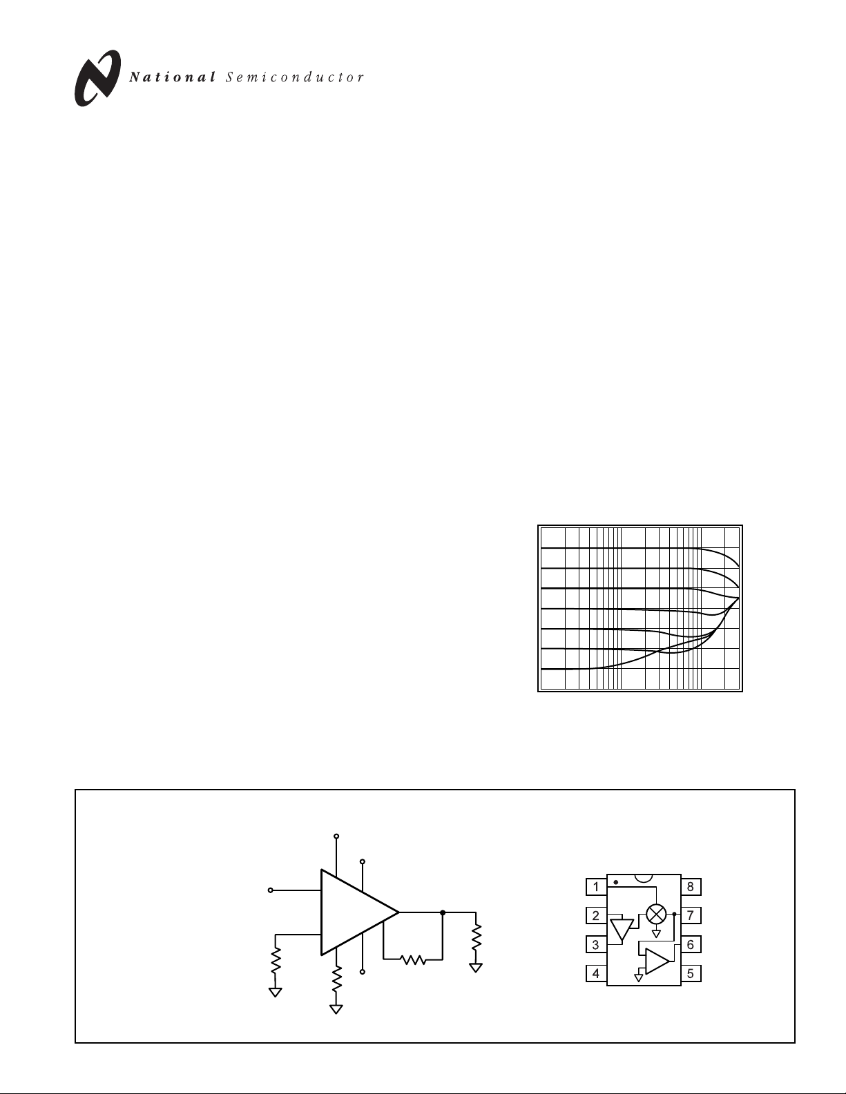
Variable Gain Amplifier
Circuit
CLC5523
Low-Power,Variable Gain Amplifier
March 2000
Features
■
Low power: 135mW
■
250MHz, -3dB bandwidth
■
Slew rate 1800V/ms
■
Gain flatness 0.2dB @ 75MHz
■
Rise & fall times 2.0ns
■
Low input voltage noise 4nV/ÖHz
Applications
■
Automatic gain control
■
Voltage controlled filters
■
Automatic signal leveling for A/D
■
Amplitude modulation
■
Variable gain transimpedance
General Descriptions
The CLC5523 is a low power, wideband, DC-coupled, voltagecontrolled gain amplifier. It provides a voltage-controlled gain
block coupled with a current feedback output amplifier. High
impedance inputs and minimum dependence of bandwidth on
gain make the CLC5523 easy to use in a wide range of
applications. This amplifier is suitable as a continuous gain
control element in a variety of electronic systems which benefit
from a wide bandwidth of 250MHz and high slew rate of
1800V/ms, with only 135mW of power dissipation.
Input impedances in the megaohm range on both the signal
and gain control inputs simplify driving the CLC5523 in any
application. The CLC5523 can be configured to use pin 3 as a
low impedance input making it an ideal interface for current
inputs. By using the CLC5523’s inverting configuration in which
RGis driven directly, inputs which exceed the device’s input
voltage range may be used.
The gain control input (VG), with a 0 to 2V input range, and a
linear-in-dB gain control, simplifies the implementation of AGC
circuits. The gain control circuit can adjust the gain as fast as
4dB/ns. Maximum gains from 2 to 100 are accurately and simply
set by two external resistors while attenuation of up to 80dB from
this gain can be achieved.
The extremely high slew rate of 1800V/ms and wide bandwidth
provides high speed rise and fall times of 2.0ns, with settling time
for a 2 volt step of only 22ns to 0.2%. In time domain applications
where linear phase is important with gain adjust, the internal current mode circuitry maintains low deviation of delay over a wide
gain adjust range.
CLC5523
Low-Power, Variable Gain Amplifier
© 2000 National Semiconductor Corporation http://www.national.com
Printed in the U.S.A.
+
-
CLC5523
R
f
V
o
V
in
R
g
2
3
4
1
V
G
R
L
5
-5V
8
+5V
6
7
25W
Pinout
DIP & SOIC
Frequency Response with Changes in V
30
20
10
0
-10
-20
-30
Magnitude (10dB/div)
-40
-50
1M
10M
Frequency (Hz)
g
100M
V
V
R
GND
G
IN
g
X1
+
+V
IV
-V
CC
O
CC
Page 2

http://www.national.com 2
CLC5523 Electrical Characteristics
(VCC= ±5V, Rf= 1k, Rg= 100W,RL= 100W,VG= 2V; unless specified)
PARAMETERS CONDITIONS TYP MIN/MAX RATINGS UNITS NOTES
Ambient Temperature CLC5523I +25˚C25˚C -40 to 85˚C
FREQUENCY DOMAIN RESPONSE
-3dB bandwidth V
o
< 0.5V
pp
250 150 125 MHz
V
o
< 4.0V
pp
100 45 35 MHz
peaking DC to 200MHz (V
o
= 0.5Vpp) 0 0.8 2.0 dB
rolloff DC to 75MHz (V
o
= 0.5Vpp) 0.2 1.0 1.2 dB
linear phase deviation DC to 75MHz (V
o
= 0.5Vpp) 0.6 1.5 3.0 deg
gain control bandwidth V
in
= 0.2VDC, Vg= 1V
DC
95 70 60 MHz
TIME DOMAIN RESPONSE
rise and fall time 0.5V step 2.0 2.8 3.0 ns
overshoot 0.5V step 6.0 15 20 %
settling time to 0.2% 2V step 22 30 60 ns
non-inverting slew rate 4V step 700 450 400 V/ms
inverting slew rate 4V step 1800 1000 700 V/ms
gain control response rate 4 dB/nS 1
DISTORTION AND NOISE RESPONSE
2
nd
harmonic distortion 1Vpp, 5MHz -65 – – dBc
3
rd
harmonic distortion 1Vpp, 5MHz -80 – – dBc
2
nd
harmonic distortion 1Vpp, 10MHz -57 -52 -40 dBc
3
rd
harmonic distortion 1Vpp, 10MHz -75 -58 -54 dBc
input referred total noise V
g
= 2V 5 6 7 nV/ÖHz
input referred voltage noise 4 5.5 5.5 nV/ÖHz
R
g
referred current noise 36 50 60 pA/ÖHz
STATIC DC PERFORMANCE
output offset voltage 50 120 150 mV A
V
in
signal input
input voltage range R
g
open ±3.8 ±3.6 ±3.3 V
input bias current 3.0 8.0 16 mAA
input resistance 3.0 1.0 0.8 MW
input capacitance 1.0 1.5 1.7 pF
I
R
g
max
0° to 70°C 7.0 5.0 4.0 mA
I
R
g
max
-40° to 85°C 7.0 5.0 2.5 mA
signal ch. non-linearity SGNL V
o
= 2V
pp
0.04 0.1 0.2 %
gain accuracy* 0.3 0.5 0.9 dB A
V
g
gain input
input bias current 0.5 2.0 4.0 mA
input resistance 10 2.0 2.0 MW
input capacitance 1.0 1.5 1.5 pF
ground pin current 40 55 65 mA
power supply rejection ratio input-referred 57 50 46 dB
supply current R
L
= ¥ 13.5 15 16 mA A
output voltage range no load ±3.4 ±3.0 ±2.3 V
output voltage range R
L
= 100W ±3.0 ±2.5 ±2.3 V
output impedance 0.1 0.15 0.15 W
output current 80 65 50 mA
transistor count 146
*maximum gain is defined as Rf/R
g
Min/max ratings are based on product characterization and simulation. Individual parameters are tested as noted. Outgoing quality levels are
determined from tested parameters.
Absolute Maximum Ratings
supply voltage
±
7V
output current ±80mA
maximum junction temperature +150˚C
storage temperature range -65˚C to +150˚C
lead temperature (soldering 10 sec) +300˚C
ESD rating (human body model) TBD
Notes
A) I-level: spec is 100% tested at +25˚C.
1) See plot
“Gain Control Settling Time”
.
Ordering Information
Model Temp Range Description
CLC5523IN -40°C to +85°C 8-pin DIP
CLC5523IM -40°C to +85°C 8-pin Small outline
CLC5523IMX -40°C to +85°C 8-pin Small outline tape and reel
Contact the factory for other packages.
Pac kage Thermal Resistance
Package q
JC
q
JA
DIP (IN) 65°C/W 115°C/W
Small Outline (IM) 55°C/W 135°C/W
Page 3

3 http://www.national.com
CLC5523 T ypical Perf ormance
(VG= +2V, Rf=1kW, Rg= 100W, RL= 100W,Vo= 0.5Vpp; unless specified)
Frequency Response (A
25
vmax
=10)
20
15
10
5
0
-5
-10
-15
Magnitude (5dB/div)
-20
-25
-30
1
10
Frequency (MHz)
Frequency Response vs. R
Magnitude
Phase
Magnitude (1dB/div)
1 10 100
L
RL = 50W
RL = 100W
Frequency (MHz)
PSRR & R
60
50
40
Magnitude (dB)
30
20
0.01 0.10 1 10 100
PSRR
R
out
out
Frequency (MHz)
Large Signal Frequency Response
V
= 1V
Inverting
Non-Inverting
Magnitude (1dB/div)
1
10
out
V
= 2V
out
V
= 4V
out
V
= 1V
out
pp
V
= 2V
out
pp
V
= 4V
out
pp
Frequency (MHz)
Gain (V/V) vs. V
10
9.0
8.0
7.0
6.0
5.0
4.0
Gain (V/V)
3.0
2.0
1.0
0
0 0.4 0.8 1.2 1.6 2.0
g
-40¡C
25¡C
85¡C
Vg Voltage (V)
100
100
pp
pp
pp
RL = 1k
Magnitude (5dB/div)
360
Phase (deg)
180
0
-180
-360
-450
100
10
R
out
(W)
1.0
0.1
0.01
Gain (dB)
Frequency Response (A
10
vmax
= 2)
5
0
-5
-10
-15
-20
-25
-30
-35
-40
-45
1
10
100
Frequency (MHz)
Frequency Response vs. R
Magnitude (1dB/div)
1 10 100
g
Rg = 500W
Rg = 10W
Rg = 33W
Rg = 100W
Frequency (MHz)
Feed-Through Isolation (VG = 0, 2)
A
= 100
40
A
= 10
vmax
20
vmax
0
-20
Gain (dB)
-40
-60
-80
1
10
100
Frequency (MHz)
Equivalent Input Noise
100
10
Voltage Noise
Current Noise
Input Voltage Noise (nVÖHz)
1
0.0001 0.001 0.01 0.1 1 10
Frequency (MHz)
Gain (dB) vs. V
20
10
0
-10
25¡C
-20
-30
-40
-50
-60
0 0.4 0.8 1.2 1.6 2.0
g
85¡C
-40¡C
Vg Voltage (V)
Magnitude (5dB/div)
1000
Input Current Noise (pAÖHz)
100
Input Voltage Noise (nVÖHz)
10
-0.5
Amplitude (0.5V/div)
-1.5
-2.5
Frequency Response (A
45
vmax
= 100)
40
35
30
25
20
15
10
5
0
-5
-10
1
10
100
Frequency (MHz)
Frequency Response vs. R
Magnitude (1dB/div)
1 10 100
Rf = 2k
Rf = 5k
f
Rf = 689W
Rf = 1k
Frequency (MHz)
Gain Flatness & Linear Phase Deviation
Vo = 2V
pp
Gain
Phase
Magnitude (0.1dB/div)
0 1530456075
Frequency (MHz)
Input Referred Total Noise
20
18
16
14
12
10
8
6
4
2
0 100 200 300 400 500
RG (W)
Large & Small Signal Pulse Response
2.5
Large
1.5
Small
0.5
Time (5ns/div)
Phase (0.5¡C/div)
0.5
0.4
Amplitude (0.1V/div)
0.3
0.2
0.1
0
-0.1
-0.2
-0.3
-0.4
-0.5
Page 4

http://www.national.com 4
CLC5523 T ypical Performance
(VG= +2V, Rf=1kW, Rg= 100W,A
vmax
= 10; unless specified)
2nd Harmonic Distortion vs. Frequency
-30
Vo = 1V
-40
-50
-60
-70
-80
Distortion (dBc)
-90
-100
pp
2nd RL = 100W
2nd RL = 1k
1
10
Frequency (MHz)
Harmonic Distortion vs. Gain
-30
-50
-70
Distortion (dBc)
-90
-110
RL = 100
3rd = 10MHz
0.1 1
Vo = 100mV
2nd = 1MHz
3rd = 1MHz
Gain (Av)
Short Term Settling Time
0.2
0.1
0
(% Output Step)
o
-0.1
V
-0.2
1 100
Vo = 2Vstep
Time (ns)
DC Offset vs. Temperature
120
100
80
60
Output Offset (mV)
40
20
-60 -20 20 60 100 140
pp
2nd = 10MHz
10
10000
Input Bias Current
Output Offset Voltage
Temperature (¡C)
3rd Harmonic Distortion vs. Frequency
-40
Vo = 1V
1
pp
3rd RL = 100W
3rd RL = 1k
10
-50
-60
-70
-80
Distortion (dBc)
-90
-100
Frequency (MHz)
Input Harmonic Distortion (Av = 2)
60
VG = 1.04V
50
VG = 0.94V
= 100W
R
g
40
Distortion (dBc)
30
20
0 0.5 1.0 1.5 2.0
R
Input Voltage (V)
Long Term Settling Time
0.15
Vo = 2Vstep
0.1
0.05
0
-0.05
(% Output Step)
-0.1
o
V
-0.15
-0.2
0.001 0.01 0.1 1.0 10
Time (ms)
2.5
Input Bias Current (mA)
2.0
1.5
1.0
Intercept (dBm)
0.5
0
Harmonic Distortion vs. Output Voltage
-50
RL = 100
-60
-70
-80
-90
Distortion (dBc)
-100
-110
0 0.5 1 1.5 2
Differential Gain & Phase (NTSC)
0.05
= 250W
g
0
Gain (%)
-0.05
-0.1
-1.6 -0.8 0.8
Gain Control Settling Time
Amplitude (0.5V/div)
100
2nd Tone, 3rd Order Intermod Intercept
50
45
40
35
30
25
20
10 20 30 40 50 60 70 80
Frequency (MHz)
2nd = 10MHz
2nd = 1MHz
3rd = 10MHz
3rd = 1MHz
Output Voltage (Vpp)
Phase
0
DC Output Voltage
V
o
V
g
Time (10ns/div)
Gain
2.5
1.6
0.05
0
Phase (deg)
-0.05
-0.1
-0.15
-0.2
-0.25
Page 5

5 http://www.national.com
The key features of the CLC5523 are:
■
Low Power
■
Broad voltage controlled gain and attenuation
range
■
Bandwidth independent, resistor programmable
gain range
■
Broad signal and gain control bandwidths
■
Frequency response may be adjusted with R
f
■
High Impedance signal and gain control Inputs
The CLC5523 combines a closed loop input buffer, a voltage controlled variable gain cell and an output amplifier.
The input buffer is a transconductance stage whose gain
is set by the gain setting resistor, Rg. The output amplifier is a current feedback op amp and is configured as a
transimpedance stage whose gain is set by, and equal to,
the feedback resistor, Rf. The maximum gain, A
vmax
, of
the CLC5523 is defined by the ratio; Rf/Rg. As the
gain control input (VG) is adjusted over its 0 to 2V range,
the gain is adjusted over a range of 80dB relative to the
maximum set gain.
Setting the CLC5523 Maximum Gain
Although the CLC5523 is specified at A
vmax
= 10, the
recommended A
vmax
varies between 2 and 100. Higher
gains are possible but usually impractical due to
output offsets, noise and distortion. When varying A
vmax
several tradeoffs are made:
Rg: determines the input voltage range
Rf: determines overall bandwidth
The amount of current which the input buffer can source
into Rgis limited and is specified in the I
Rgmax
spec. This
sets the maximum input voltage:
The effects of maximum input range on harmonic distortion
are illustrated in the
Input Harmonic Distortion
plot.
Variations in Rgwill also have an effect on the small
signal bandwidth due to its loading of the input buffer and
can be seen in
Frequency Response vs.R
g
. Changes in
Rfwill have a more dramatic effect on the small signal
bandwidth. The output amplifier of the CLC5523 is a
current feedback amplifier(CFA) and its bandwidth is
determined by Rf. As with any CFA, doubling the feedback resistor will roughly cut the bandwidth of the device
in half (refer to the plot
Frequency Response vs.R
f
). For
more information covering CFA’s, there is
a basic tutorial, OA-20,
Current Feedback Myths
Debunked
or a more rigorous analysis, OA-13,
Current
Feedback Amplifier Loop Gain Analysis and P erf ormance
Enhancements
.
Using the CLC5523 in AGC Applications
In AGC applications, the control loop f orces the CLC5523
to have a fix ed output amplitude. The input amplitude will
vary over a wide range and this can be the issue that
limits dynamic range. At high input amplitudes, the
distortion due to the input buffer driving Rgmay exceed
that which is produced by the output amplifier driving the
load. In the plot,
Harmonic Distortion vs. Gain
, second
and third harmonic distortion are plotted over a gain
range of nearly 40dB for a fixed output amplitude
of 100mVppin the specified configuration, Rf= 1k,
Rg= 100W. When the gain is adjusted to 0.1 (i.e. 40dB
down from A
vmax
), the input amplitude would be 1Vppand
we can see the distortion is at its worst at this gain. If the
output amplitude of the AGC were to be raised above
100mV, the input amplitudes for gains 40dB down from
A
vmax
would be even higher and the distortion would
degrade further. It is for this reason that we recommend
lower output amplitudes if wide gain ranges are desired.
Using a post-amp like the CLC404 or CLC409 would be
the best way to preserve dynamic range and yield output
amplitudes much higher than 100mVpp.
Another way of addressing distortion performance and
its limitations on dynamic range, would be to raise the
value of Rg. Just like any other high-speed amplifier, by
increasing the load resistance, and therefore decreasing
the demanded load current, the distortion performance
will be improved in most cases. With an increased Rg, R
f
will also have to be increased to keep the same A
vmax
and this will decrease the overall bandwidth.
Gain Partitioning
If high levels of gain are needed, gain partitioning should
be considered.
Figure 1: Gain Partitioning
The maximum gain range for this circuit is given by the
following equation:
CLC5523 Operation
R
A
vmax
f
=
R
g
V (max) I R
in R max
=×
g
g
V
G
V
in
+
CLC425
R
R
1
25Wž
R
c
2
R
g
2
3
25W
1
CLC5523
4
6
7
R
f
V
o
æ
maximum gain 1
æ
=+
ç
è
ö
R
2
÷
R
ø
1
ö
R
f
×
ç
÷
R
è
ø
g
Page 6

http://www.national.com 6
The CLC425 is a low noise wideband voltage feedback
amplifier. Setting R2 at 909W and R1 at 100W produces
a gain of 20dB. Setting Rfat 1000W as recommended
and Rgat 50W, produces a gain of 26dB in the CLC5523.
The total gain of this circuit is therefore approximately
46dB. It is important to understand that when partitioning
to obtain high levels of gain, very small signal levels will
drive the amplifiers to full scale output. For example, with
46dB of gain, a 20mV signal at the input will drive the output of the CLC425 to 200mV, the output of the CLC5523
to 4V. Accordingly, the designer must carefully consider
the contributions of each stage to the overall characteristics. Through gain partitioning the designer is provided
with an opportunity to optimize the frequency response,
noise, distortion, settling time, and loading effects
of each amplifier to achieve improved overall
performance.
CLC5523 Gain Control Range and Minimum Gain
Before discussing Gain Control Range, it is important to
understand the issues which limit it. The minim um gain of
the CLC5523, theoretically, is zero, but in practical circuits
is limited by the amount of feedthrough, here defined as
the difference in output levels when VG= 2V and when
VG= 0V. Capacitive coupling through the board and
package as well as coupling through the supplies will
determine the amount of feedthrough. Even at DC, the
input signal will not be completely rejected. At high frequencies feedthrough will get worse because of its capacitive nature. At low frequencies, the feedthrough
will be
80dB below the maximum gain, and therefore it can
be said
that the CLC5523 has an 80dB Gain Control Range.
CLC5523 Gain Control Function
In the two plots,
Gain vs. V
G
, we can see the gain as a
function of the control voltage. The first plot, sometimes
referred to as the S-curve, is the linear (V/V ) gain. This
is a hyperbolic tangent relationship. The second gain
curve plots the gain in dB and is linear over a wide range
of gains. Because of this, the CLC5523 gain control is
referred to as “linear-in-dB.”
For applications where the CLC5523 will be used at the
heart of a closed loop AGC circuit, the S-curve control
characteristic provides a broad linear (in dB) control
range with soft limiting at the highest gains where large
changes in control voltage result in small changes in
gain. For applications, requiring a fully linear (in dB)
control characteristic, use the CLC5523 at half gain and
below (V
G
² 1V).
Avoiding Overdrive of the CLC5523
Gain Control Input
There is an additional requirement for the CLC5523 Gain
Control Input (VG): VGmust not exceed +2.5V. The gain
control circuitry may saturate and the gain may actually
be reduced. In applications where VGis being driven
from a DA C , this can easily be addressed in the softw are.
If there is a linear loop driving VG, such as an AGC loop,
other methods of limiting the input voltage should be
implemented. One simple solution is to place a 2:1
resistive divider on the VGinput. If the device driving this
divider is operating off of ±5V supplies as well, its output
will not exceed 5V and through the divider VGcan not
exceed 2.5V.
Improving the CLC5523 Large Signal Performance
Figure 2 illustrates an inverting gain scheme for the
CLC5523.
Figure 2: Inverting the CLC5523
The input signal is applied through the Rgresistor. The
Vinpin should be grounded through a 25W resistor. The
maximum gain range of this configuration is given in the
following equation:
The inverting slew rate of the CLC5523 is much higher
than that of the non-inverting slew rate. This 2.5X
performance improvement comes about because in the
non-inverting configuration, the slew rate of the overall
amplifier is limited by the input buffer. In the inverting
circuit, the input buffer remains at a fixed voltage and
does not affect slew rate.
Transmission Line Matching
One method for matching the characteristic impedance of
a transmission line is to place the appropriate resistor at
the input or output of the amplifier. Figure 3 shows a typical circuit configuration for matching transmission lines.
Figure 3:Transmission Line Matching
The resistors Rs, Ri, Ro, and RTare equal to the
characteristic impedance, Zo, of the transmission line or
cable. Use Coto match the output transmission line over
a greater frequency range. It compensates for the
increase of the op amp’s output impedance with frequency.
V
G
1
2
25W
CLC5523
V
in
3
R
g
4
6
7
R
V
o
f
25W
æ
ö
R
A
vmax
=-
f
ç
÷
R
è
ø
g
V
G
C
o
Z
o
6
R
R
o
f
Output
R
T
Signal
Input
Z
o
R
s
+
-
R
i
R
g
2
3
25W
1
CLC5523
4
7
Page 7

7 http://www.national.com
Minimizing Parasitic Effects on
Small Signal Bandwidth
The best way to minimize parasitic effects is to use the
small outline package and surface mount components.
For designs utilizing through-hole components,
specifically axial resistors, resistor self-capacitance
should be considered. Example: the average magnitude
of parasitic capacitance of RN55D 1% metal film
resistors is about 0.15pF with variations of as much as
0.1pF between lots. Given the CLC5523’s extended
bandwidth, these small parasitic reactance variations can
cause measurable frequency response variations in the
highest octave. We therefore recommend the use
of surface mount resistors to minimize these parasitic
reactance effects. If an axial component is preferred, we
recommend PRP8351 resistors which are available from
Precision Resistive Products, Inc., Highway 61 South,
Mediapolis, Iowa.
Small Signal Response at Low A
vmax
When the maximum gain, as set by Rgand Rf, is greater
than or equal to A
vmax
= 10, little or no peaking should be
observed in the amplifier response. When the gain range
is set to less than A
vmax
= 10, some peaking may
be observed at higher frequencies. At gain ranges of
2 ² A
vmax
² 10 peaking can be minimized by increasing
Rf. At gain ranges of A
vmax
< 2 peaking reaches
approximately 6dB in the upper octave.
If peaking is observed with the recommended Rfresistor,
and a small increase in the Rfresistor does not solve the
problem, then investigate the possible causes and
remedies listed below.
■
Capacitance across R
f
■
Do not place a capacitor across R
f
■
Keep traces connecting Rfseparated and as
short as possible
■
Capacitive Loads
■
Place a small resistor (20-50W) between the
output and C
L
■
Long traces and/or lead lengths between R
f
and the CLC5523
■
Keep these traces as short as possible
■
Long traces between CLC5523 and 0.1mF
bypass capacitors
■
Keep these traces less than 0.2 inches (5mm)
■
For the devices in the PDIP package, an
additional 1000pF monolithic capacitor should be
placed less than 0.1” (3mm) from the pin
■
Extra capacitance between the Rgpin and
ground (CG)
■
See the
Printed Circuit Board Layout
sub-section
below for suggestions on reducing C
G
■
Increase Rfif peaking is still observed after
reducing C
G
■
Non-inverting input pin connected directly to
ground
■
Place a 50 to 200W resistor between the noninverting pin and ground
Adjusting Offsets and DC Level Shifting
Offsets can be broken into two parts: an input-referred term
and an output-referred term. These errors can be tr immed
using the circuit in Figure 4. First set VGto 0V and adjust
the trim pot R4 to null the offset voltage at the output. This
will eliminate the output stage offsets. Next set VGto 2V
and adjust the trim pot R1 to null the offset voltage at the
output. This will eliminate the input stage offsets.
Figure 4: Offset Adjust Circuit
V
G
1
2
CLC5523
3
g
4
25W
6
7
R
R3
10k
0.1mF
V
o
f
+5V
R4
10k
-5V
+5V
R1
10k
-5V
R2
10k
0.1mF
V
in
R
Page 8

http://www.national.com 8
Evaluation Boards
Evaluation boards are available for both the 8-pin DIP
and small outline package types. Evaluation kits that
contain an evaluation board and CLC5523 samples can
be obtained by calling National Semiconductor’s
Customer Service Center at 1-800-272-9959. The 8-pin
DIP evaluation kit part number is CLC730065. The 8-pin
small outline evaluation kit part number is CLC730066.
The DIP evaluation kit has been designed to utilize axial
lead components. The small outline evaluation kit has
been designed to utilize surface mount components.
The circuit diagram shown in Figure 5, applies to both the
DIP and the small outline evaluation boards.
Figure 5: Evaluation Board Schematic
Printed Circuit Board Layout
High frequency op amp performance is strongly
dependent on proper layout, proper resistive termination
and adequate power supply decoupling. The most important layout points to follow are:
■
Use a ground plane
■
Bypass each power supply pin with these capacitors:
■
a high-quality 0.1mF ceramic capacitor placed
less than 0.2” (5mm) from the pin
■
a 6.8mF tantalum capacitor less than 2” (50mm)
from the pin
■
for the plastic DIP package, a high-quality
1000pF ceramic capacitor placed less than 0.1”
(3mm) from the pin
Capacitively bypassing pow er pins to a good ground plane
with a minimum of trace length (inductance) is necessary
for any high speed device, but it is particularly important for
the CLC5523.
■
Establish wide, low impedance, power supply traces
■
For the plastic DIP package, a 25W resistor should
be connected from pin 4 to ground with a minimum
length trace
■
Minimize or eliminate sources of capacitance
between the Rfpin and the output pin. Avoid
adjacent feedthrough vias between the Rfand
output leads since such a geometry may give rise
to a significant source of capacitance.
■
Minimize trace and lead lengths for components
between the inverting and output pins
■
Remove ground plane 0.1” (3mm) from all
input/output pads
■
For prototyping, use flush-mount printed circuit
board pins;
never use high profile DIP sockets
To minimize high frequency distortion, other layout issues
need be addressed:
■
Short, equal length, low impedance power supply
return paths from the load to the supplies
■
avoid returning output ground currents near the
input stage.
Input
Signal
V
GND
25W
G
V
in
X1
R
g
*
Gain
Control
50W
RX
R
50W
in
R
100W
g
5V
6.8mF
+V
CC
R
I-
1kWž
V
o
-
-V
+
CC
0.1mF
f
R
o
Output
50Wž
0.1mF 6.8mF
-5V
* 25W series resistor is not required on the
small outline device and does not appear on
the small outline board
Page 9

9 http://www.national.com
Figure 6: DIP Evaluation Board (Top Layer) Figure 7: DIP Evaluation Board (Bottom Layer)
Comlinear Layer1
Figure 8: Small Outline Evaluation Board
(Top Layer)
Figure 9: Small Outline Evaluation Board
(Bottom Layer)
(Not drawn to scale)
Comlinear Layer2
EVAL BOARD
CLC5523
Comlinear Layer1 Silk
Comlinear Layer2 Silk
C4
J5
Ro
C3
CLC5523 EVAL BOARD
Page 10

http://www.national.com 10
Digital Gain Control
Digitally variable gain control can be easily realized
by driving the CLC5523’s gain control input with a
digital-to-analog converter (DAC). Figure 10 illustrates
such an application. This circuit employs National
Semiconductor’s eight-bit DAC0830, the LM351 JFET
input op-amp, and the CLC5523 V GA. With V
ref
set to 2V,
the circuit provides up to 80dB of gain control in
512 steps with up to 0.05% full scale resolution. The
maximum gain of this circuit is 20dB.
Figure 10: Digital Gain Control
Automatic Gain Control (AGC) #1
Fast Response AGC Loop
The AGC circuit shown in Figure 11 will correct a 6dB
input amplitude step in 100ns. The circuit includes a two
op-amp precision rectifier amplitude detector (U1 and
U2), and an integrator (U3) to provide high loop gain at
low frequencies.The output amplitude is set by R9.
Some notes on building fast AGC loops:
Precision rectifiers work best with large output signals.
Accuracy is improved b y bloc king DC offsets, as shown in
Figure 11.
Signal frequencies must not reach the gain control port of
the CLC5523, or the output signal will be distorted
(modulated by itself). A fast settling AGC needs
additional filtering beyond the integrator stage to
block signal frequencies. This is provided in Figure 11
by a simple R-C filter (R10 and C3); better distortion
performance can be achieved with a more complex filter.
These filters should be scaled with the input signal
frequency. Loops with slower response time (longer
integration time constants) may not need the R10 –
C3 filter.
Checking the loop stability can be done by monitoring the
Vgvoltage while applying a step change in input signal
amplitude. Changing the input signal amplitude can be
easily done with either an arbitrary waveform generator
or a fast multiplexer such as the CLC532.
Automatic Gain Control (AGC) #2
Figure 12 on the following page, illustrates an automatic
gain control circuit that employs two CLC5523’s. In this
circuit, U1 receives the input signal and produces an
output signal of constant amplitude. U2 is configured
to provide negative feedback. U2 generates a rectified
gain control signal that works against an adjustable
bias level which may be set by the potentiometer and
Rb.Ciintegrates the bias and negative feedback. The
resultant gain control signal is applied to the U1 gain
control input Vg. The bias adjustment allows the U1
output to be set at an arbitrary level less than the
maximum output specification of the amplifier.
Rectification is accomplished in U2 by driving both
the amplifier input and the gain control input with the
U1 output signal. The voltage divider that is formed
by R1, R2 and the Vginput (pin 1) resistance, sets the
rectifier gain.
CLC5523 Applications
Figure 11: Automatic Gain Control Circuit #1
Digital
Input
R
fb
I
o1
V
ref
-
LM351DAC0830
+
I
o2
R
100W
V
in
G
2
3
25W
1
CLC5523
4
R
1k
V
o
f
6
7
Includes scope
probe capacitance
2
+
CLC5523
3
-
1
4
R10
500W
C2
C3
40pF
V
R
100W
in
g
680pF
U2
CLC404
R7
+
-
U3
CLC426
-
R8
500W
+
R9
4.22k
500W
-5V
6
7
R5
25W
R
f
R6
500W
1N5712
Schottky
R4
500W
CLC404
R3
500W
U1
Output
20MHz,
0.1V
C1
pp
1.0mF
R1
20W
-
+
R2
25W
Page 11

11 http://www.national.com
+5V
Figure 12: Automatic Gain Control Circuit #2
2k
Level Adj.
-5V
Signal
Input
R
b
R
100W
R
c
100W
2.2mF
Output
150W
R
100W
1
g1
100W
2
CLC5523
3
C
i
100pF
1
U1
4
6
7
R
50W
f1
1k
25W
R
g2
100W
2
CLC5523
3
1
U2
4
6
7
R
f2
1k
Page 12

CLC5523
Low-Power, Variable Gain Amplifier
http://www.national.com 12
LIFE SUPPORT POLICY
NATIONAL’S PRODUCTS ARE NOT AUTHORIZED FOR USE AS CRITICAL COMPONENTS IN LIFE SUPPORT DEVICES
OR SYSTEMS WITHOUT THE EXPRESS WRITTEN APPROVAL OF THE PRESIDENT AND GENERAL COUNSEL OF
NATIONAL SEMICONDUCTOR CORPORATION. As used herein:
1. Life support devices or systems are devices or systems which, a) are intended for surgical implant into the body, or b)
support or sustain life, and whose failure to perform, when properly used in accordance with instructions for use provided
in the labeling, can be reasonably expected to result in a significant injury to the user.
2. A cr itical component is any component of a life support device or system whose failure to perform can be reasonably
expected to cause the failure of the life support device or system, or to affect its safety or effectiveness.
National Semiconductor National Semiconductor National Semiconductor National Semiconductor
Corporation Europe Asia Pacific Customer Japan Ltd.
Americas Fax:+49 (0) 1 80-530 85 86 Response Group Tel: 81-3-5639-7560
Tel: 1(800) 272-9959 E-mail: europe.support.nsc.com Tel: 65-25-2544466 Fax:81-3-5639-7507
Fax:1(800) 737-7018 Deutsch Tel:+49 (0) 1 80-530 85 85 Fax:65-2504466
Email: support@nsc.com English Tel: +49 (0) 1 80-532 78 32 Email: sea.support@nsc.com
Francais Tel: +49 (0) 1 80-532 93 58
Italiano Tel: +49 (0) 1 80-534 16 80
National does not assume any responsibility for use of any circuitry described, no circuit patent licenses are implied and National reserves the right at any time without notice to change said circuitry and specifications.
 Loading...