

Page 1
Features
■
130MHz bandwidth (Av = +2)
■
96mA output current
■
1.5mA supply current
■
-85/-75dBc HD2/HD3
■
15ns settling to 0.2%
■
-74dBc input-referred crosstalk (5MHz)
■
Single version available (CLC408)
Applications
■
ADSL/HDSL driver
■
Coaxial cable driver
■
UTP differential line driver
■
Transformer/coil driver
■
High capacitive-load driver
■
Video line driver
■
Portable/battery-powered line driver
■
Differential A/D driver
V
o1
V
inv1
V
non-inv1
V
EE
V
o2
V
inv2
V
non-inv2
V
CC
+
-
1/2
CLC418
R
g2
+
V
o
-
-
+
R
t2
R
f2
R
f1
R
g1
1/2
CLC418
V
in
R
t1
R
m/2
R
m/2
R
L
Z
o
UTP
I
o
R
eq
I:n
V
d/2
-V
d/2
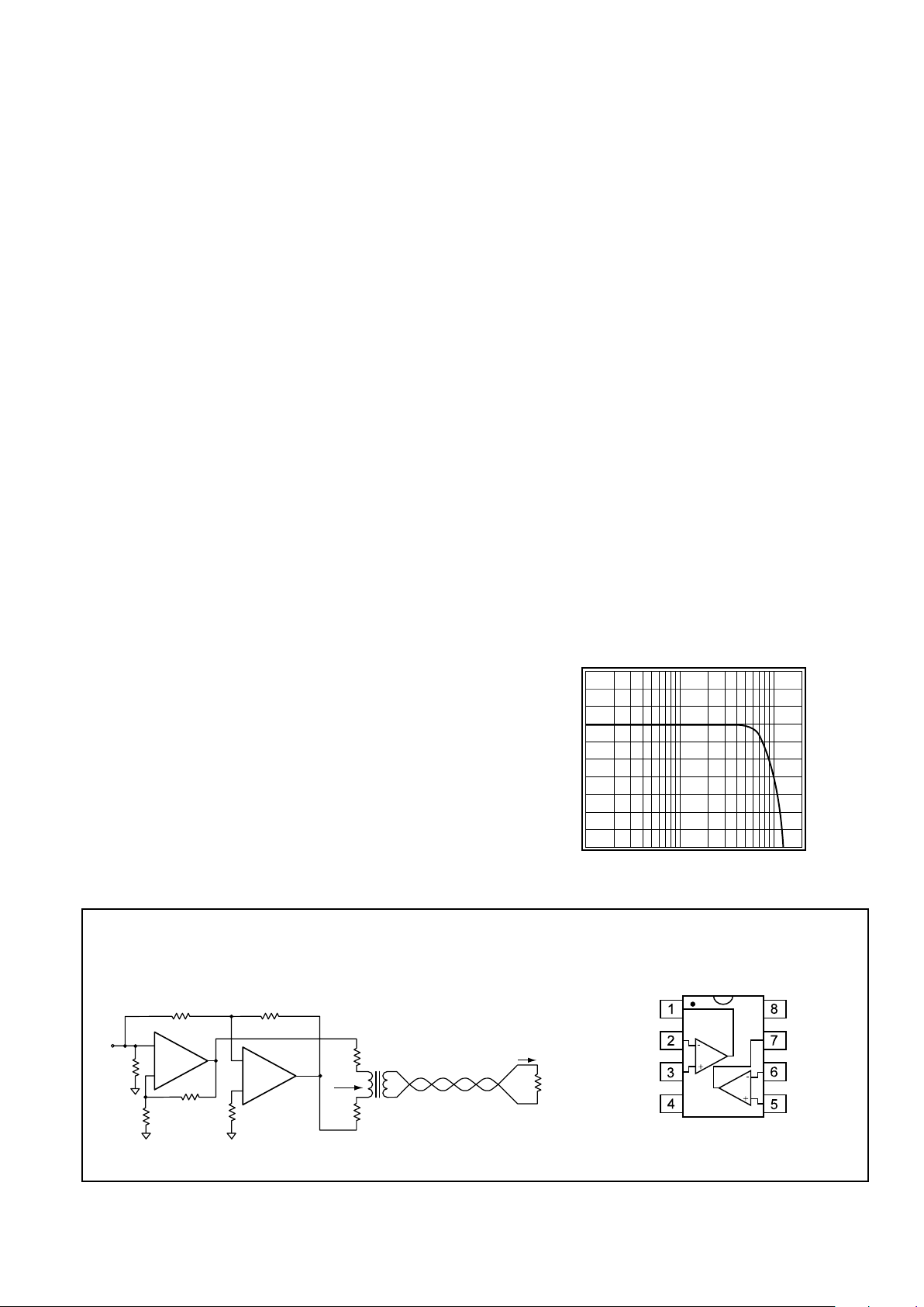
Typical Application Diagram
Differential Line Driver
with Load Impedance Conversion
Pinout
DIP & SOIC
General Description
The Comlinear CLC418 dual high-speed current-feedback
operational amplifier is designed to drive low-impedance and
high capacitance loads while maintaining high signal fidelity.
Operating on ±5V power supplies, each of the CLC418’s
amplifiers produces a continuous 96mA output current. Into a
back-terminated 50
Ω load, the devices produce -85/-64dBc
second/third harmonic distortion (Av = +2, Vo = 2Vpp, f = 1MHz).
The CLC418’s current-feedback architecture maintains consistent
performance over a wide range of gain and signal levels. DC gain
and bandwidth can be set independently. With proper resistor
selection, either maximally flat gain response or linear phase
response can be selected.
Requiring a mere 15mW quiescent power per amplifier, the
CLC418 offers superior performance-vs-power with a 130MHz
small-signal bandwidth, 350V/ms slew rate and quick 4.6ns
rise/fall times (2Vstep). The combination of low quiescent power,
high output current drive and high performance make the
CLC418 a great choice for many battery-powered personal
communication/computing systems.
Combining the CLC418’s two amplifiers (shown below) results in
a powerful differential line driver for driving video signals over
unshielded twisted-pair (UTP). The CLC418 can also be used for
driving differential-input step-up transformers for applications
such as Asynchronous Digital Subscriber Lines (ADSL) or HighBit-Rate Digital Subscriber Lines (HDSL).
The CLC418’s amplifiers make excellent low-power highresolution A-to-D converter drivers with their very fast 15ns settling time (to 0.2%) and ultra-low -85/-75dBc harmonic distortion
(Av = +2, Vo = 2Vpp, f = 1MHz, RL= 1kΩ).
Non-Inverting Frequency Response
(Av = +2V/V, RL = 100Ω)
Normalized Magnitude (1dB/div)
Frequency (Hz)
10M
1M 100M
Comlinear CLC418
Dual High-Speed, Low-Power Line Driver
N
August 1996
Comlinear CLC418
Dual High-Speed, Low-Power Line Driver
© 1996 National Semiconductor Corporation http://www.national.com
Printed in the U.S.A.
Page 2

http://www.national.com 2
PARAMETERS CONDITIONS TYP MIN/MAX RATINGS UNITS NOTES
Ambient Temperature CLC418AJ +25˚C +25˚C 0 to 70˚C -40 to 85˚C
FREQUENCY DOMAIN RESPONSE
-3dB bandwidth V
o
< 1.0V
pp
130 80 80 75 MHz B
V
o
< 4.0V
pp
45 33 29 28 MHz
-
0.1dB bandwidth Vo< 1.0V
pp
30 25 20 20 MHz
gain flatness V
o
< 1.0V
pp
peaking DC to 200MHz 0 0.5 0.9 1.0 dB B
rolloff <30MHz 0.2 0.45 0.6 0.6 dB B
linear phase deviation <30MHz 0.2 0.4 0.5 0.5 deg
differential gain NTSC, R
L
=150Ω 0.1 – – – %
differential phase NTSC, R
L
=150Ω 0.4 – – – deg
TIME DOMAIN RESPONSE
rise and fall time 2V step 4.6 7.0 7.5 8.0 ns
settling time to 0.2% 2V step 15 30 38 40 ns
overshoot 2V step 5 12 12 12 %
slew rate A
V
= +2 2V step 350 260 225 215 V/µs
DISTORTION AND NOISE RESPONSE
2
nd
harmonic distortion 2Vpp, 1MHz -85 – – – dBc
2V
pp
, 1MHz; RL= 1kΩ -85 – – – dBc
2V
pp
, 5MHz -65 -60 -58 -58 dBc B
3
rd
harmonic distortion 2Vpp, 1MHz -64 – – – dBc
2V
pp
, 1MHz; RL= 1kΩ -75 – – – dBc
2V
pp
, 5MHz -50 -45 -44 -44 dBc B
crosstalk (input-referred) 2V
pp
, 5MHz -74 -68 -68 -68 dBc
equivalent input noise
voltage (e
ni
) >1MHz 5 6.3 6.6 6.7 nV/√Hz
non-inverting current (i
bn
) >1MHz 1.4 1.8 1.9 2.3 pA/√Hz
inverting current (i
bi
) >1MHz 13 16 17 18 pA/√Hz
STATIC DC PERFORMANCE
input offset voltage 2 8 11 11 mV A
average drift 25 – 35 40 µV/˚C
input bias current (non-inverting) 2 8 11 15 µA A
average drift 60 – 80 110 nA/˚C
input bias current (inverting) 2 10 18 20 µA A
average drift 20 – 90 110 nA/˚C
power supply rejection ratio DC 55 50 48 48 dB B
common-mode rejection ratio DC 52 48 46 46 dB
supply current R
L
= ∞, 2 channels 3.0 3.4 3.6 3.6 mA A
MISCELLANEOUS PERFORMANCE
input resistance (non-inverting) 5 3 2.5 1 MΩ
input capacitance (non-inverting) 1 2 2 2 pF
common mode input range
±
2.7
±
2.3
±
2.2
±
2.0 V
output voltage range R
L
= 100Ω
±
3.3
±
2.9
±
2.8
±
2.6 V
output voltage range R
L
= ∞
±
4.0
±
3.8
±
3.7
±
3.5 V
output current 96 96 96 60 mA C
output resistance, closed loop DC 0.03 0.15 0.2 0.3 Ω
CLC418 Electrical Characteristics
(AV= +2, Rf= 1kΩ, Vcc= + 5V , RL= 100Ω, T = 25°C;unless specified)
Absolute Maximum Ratings
supply voltage
±
7V
output current (see note C) 96mA
common-mode input voltage
±
V
CC
maximum junction temperature +175°C
storage temperature range -65°C to +150°C
lead temperature (soldering 10 sec) +300°C
ESD rating (human body model) 4000V
Notes
A) J-level: spec is 100% tested at +25°C, sample tested at +85°C.
L-level: spec is 100% wafer probed at +25°C.
B)J-level: spec is sample tested at +25°C.
C)The output current sourced or sunk by the CLC418 can
exceed the maximum safe output current limit.
2
Min/max ratings are based on product characterization and simulation. Individual parameters are tested as noted. Outgoing quality levels are
determined from tested parameters.
Page 3
3 http://www.national.com
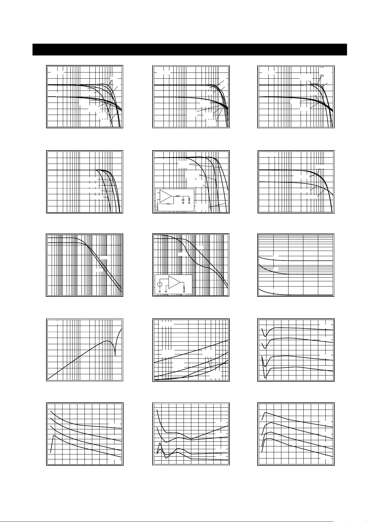
Typical Performance Characteristics
(Av= +2, Rf= 1kΩ, RL= 100Ω, VCC= + 5V, T = 25°C; CLC418AJ; unless specified)
Non-Inverting Frequency Response
Normalized Magnitude (1dB/div)
Frequency (Hz)
10M
Phase (deg)
-90
-180
-450
-270
-360
1M 100M
Av+1
Av+2
Rf=953
Av+2
Av+5
Rf=402
Av+5
Av+10
Rf=200
Av+10
Av+1
Rf=3k
0
Vo = 1V
pp
Gain
Phase
Inverting Frequency Response
Normalized Magnitude (1dB/div)
Frequency (Hz)
10M
Phase (deg)
0
-270
-360
-450
-90
-180
1M 100M
Av-1
Av-2
Rf=681
Av-2
Av-5
Rf=301
Av-5
Av-10
Rf=200
Av-10
Av-1
R
f
=806
Gain
Phase
Vo = 1V
pp
Frequency Response vs. R
L
Normalized Magnitude (1dB/div)
Frequency (Hz)
10M
Phase (deg)
-90
-180
-450
-270
-360
1M 100M
RL=1k
R
f
=1.21k
RL=25
RL=100
RL=100
Rf=1k
RL=1k
RL=25
Rf=0.95k
0
Gain
Phase
Vo = 1V
pp
Frequency Response vs. V
out
Normalized Magnitude (1dB/div)
Frequency (Hz)
10M
1M 100M
0.10V
pp
2.0V
pp
4.0V
pp
1.0V
pp
Frequency Response vs. Capacitive Load
Magnitude (1dB/div)
Frequency (Hz)
10M
1M 100M
CL=100pF
Rs =24.9
CL=10pF
Rs =100
C
L
= 1000pF
Rs =5.7
C
L
1k
R
s
+
-
1k
1k
CL=0pF
Rs =0
V
o
= 1V
pp
Small Signal Channel Matching
Normalized Magnitude (1dB/div)
Frequency (Hz)
1M
10M
100M
Vo = 1V
pp
Phase (deg)
-180
-225
-135
-90
-45
0
Channel A
Channel B
Channel A
Channel B
PSRR and CMRR
PSRR/CMRR (dB)
Frequency (Hz)
60
50
20
10
0
1k
10k
100k
40
30
CMRR
1M 10M 100M
PSRR
Open Loop Transimpedance Gain, Z(s)
Magnitude (Ω)
Frequency (Hz)
1M
100k
100
1k
10k
100M
10k
1k
Gain
Phase (deg)
180
140
20
100
60
Phase
100k 1M 10M
100Ω
-
+
CLC418
V
o
I
i
Equivalent Input Noise
Noise Voltage (nV/√Hz)
Frequency (Hz)
100
1
1k
10k
100M
10
i
bi
Noise Current (pA/√Hz)
100
10
1
100k 1M 10M
e
ni
i
bn
Input-Referred Crosstalk
Crosstalk (dB)
Frequency (Hz)
-40
-60
-50
-90
1M
10M
100M
-70
-80
Vo = 1V
pp
2nd & 3rd Harmonic Distortion
Distortion (dBc)
Frequency (Hz)
-50
-40
-30
-20
-60
-90
1M
10M
-70
-80
2nd
RL = 1k
3rd
RL = 100
3rd
RL = 1k
2nd
RL = 100
Vo = 2V
pp
2nd Harmonic Distortion, RL = 25Ω
Distortion (dBc)
Output Amplitude (Vpp)
-55
-50
-45
-60
-75
0
1
5
-65
-70
1MHz
2 3 4
2MHz
5MHz
10MHz
3rd Harmonic Distortion, RL = 25Ω
Distortion (dBc)
Output Amplitude (Vpp)
-40
-30
-20
-50
-80
0
1
5
-60
-70
1MHz
2 3 4
2MHz
5MHz
10MHz
2nd Harmonic Distortion, RL = 100Ω
Distortion (dBc)
Output Amplitude (Vpp)
-90
-85
-80
-75
-70
-65
-60
-55
-50
0
1
5
1MHz
2 3 4
2MHz
5MHz
10MHz
3rd Harmonic Distortion, RL = 100Ω
Distortion (dBc)
Output Amplitude (Vpp)
-80
-70
-60
-50
-40
-30
0
1
5
1MHz
2 3 4
2MHz
5MHz
10MHz
Page 4
http://www.national.com 4
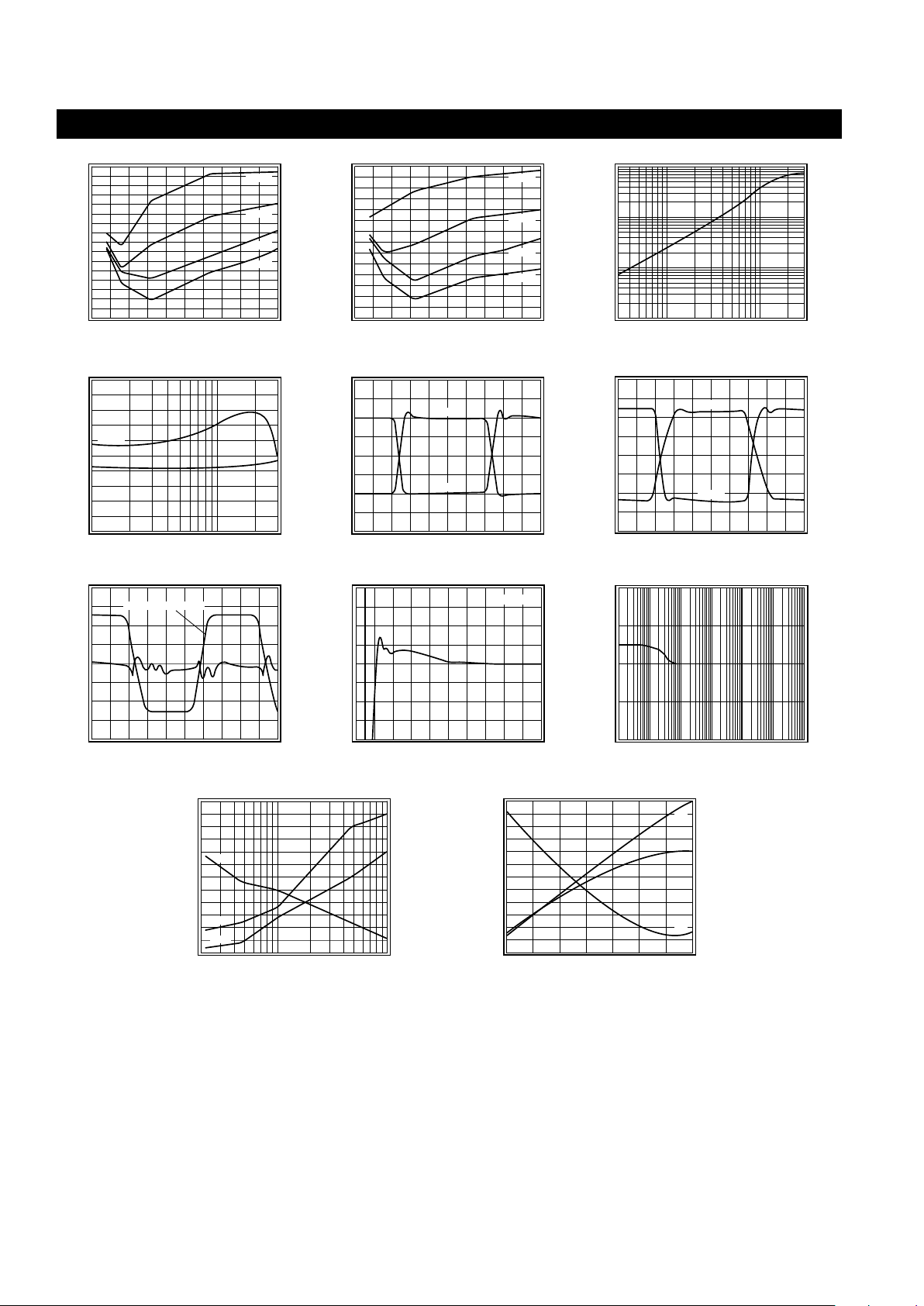
Typical Performance Characteristics
(Av= +2, Rf= 1kΩ, RL= 100Ω, VCC= + 5V, T = 25°C; CLC418AJ; unless specified)
3rd Harmonic Distortion, RL = 1kΩ
Distortion (dBc)
Output Amplitude (Vpp)
-95
-90
-85
-80
-75
-70
-65
-60
-55
0
1
5
1MHz
2 3 4
2MHz
5MHz
10MHz
2nd Harmonic Distortion, RL = 1kΩ
Distortion (dBc)
Output Amplitude (Vpp)
-95
-90
-85
-80
-75
-70
-65
-60
0
1
5
1MHz
2 3 4
2MHz
5MHz
10MHz
Closed Loop Output Resistance
Output Resistance (Ω)
Frequency (Hz)
100
0.1
10M
100M
10
1
Gain Flatness & Linear Phase Deviation
Magnitude (0.1dB/div)
Frequency (Hz)
1M
10M
Gain
Phase Deviation (0.1°/div)
Phase
Small Signal Pulse Response
Output Voltage
Time (10ns/div)
0.20
0.10
-0.20
0
-0.10
Av+2
Av-2
Large Signal Pulse Response
Output Voltage
Time (10ns/div)
4.0
2.0
-4.0
0
-2.0
Av+2
Av-2
Pulse Crosstalk
Active Channel Output (1V/div)
Time (10ns/div)
Active Output Channel
Other Channel Output (20mV/div)
Short Term Settling Time
V
o
(% Output Step)
Time (s)
0.2
0.1
-0.2
0
20n
100n
0
-0.1
V
out
= 2V
step
40n 60n 80n
Long Term Settling Time
V
o
(% Output Step)
Time (s)
0.4
-0.4
1
µ
1m
1
0
10
µ
100
µ
10m 100m
-0.2
0.2
Settling Time vs. Capacitive Load
Settling Time (ns)
CL (F)
70
60
30
20
10
100p20p
1000p
50
40
Rs (Ω)
60
50
20
10
0
40
30
R
s
0.05%
0.1%
IBI, IBN, VOS vs. Temperature
Offset Voltage V
OS
(mV)
Temperature (°C)
7.0
6.0
1.0
-50
0
100
5.0
4.0
3.0
2.0
V
OS
I
BI
, I
BN
(µA)
3.5
3.0
1.5
1.0
0.5
2.5
2.0
50
I
BI
I
BN
Page 5

5 http://www.national.com
CLC418 OPERATION
The CLC418 has a current-feedback (CFB) architecture
built in an advanced complementary bipolar process.
The key features of current-feedback are:
■
AC bandwidth is independent of voltage gain
■
Inherently unity-gain stability
■
Frequency response may be adjusted with
feedback resistor (Rf in Figures 1-3)
■
High slew rate
■
Low variation in performance for a wide range
of gains, signal levels and loads
■
Fast settling
Current-feedback operation can be explained with a
simple model. The voltage gain for the circuits in Figures 1
and 2 is approximately:
where:
■
Avis the DC voltage gain
■
Rfis the feedback resistor
■
Z(jω) is the CLC418’s open-loop
transimpedance gain
■
is the loop gain
The denominator of the equation above is approximately
1 at low frequencies. Near the -3dB corner
frequency, the interaction between Rfand Z(jω)
dominates the circuit performance. Increasing Rfdoes
the following:
■
Decreases loop gain
■
Decreases bandwidth
■
Reduces gain peaking
■
Lowers pulse response overshoot
■
Affects frequency response phase linearity
CLC418 DESIGN INFORMATION
Standard op amp circuits work with CFB op amps. There
are 3 unique design considerations for CFB:
■
The feedback resistor (Rfin Figures 1-3) sets
AC performance
■
Rfcannot be replaced with a short or a capacitor
■
The output offset voltage is not reduced by
balancing input resistances
The following sub-sections cover:
■
Design parameters, formulas and techniques
■
Interfaces
■
Application circuits
■
Layout techniques
■
SPICE model information
DC Gain (non-inverting)
The non-inverting DC voltage gain for the configuration
shown in Figure 1 is:
Figure 1: Non-Inverting Gain
The normalized gain plots in the
Typical Performance
Characteristics
section show different feedback
resistors (Rf) for different gains. These values of Rfare
recommended for obtaining the highest bandwidth with
minimal peaking. The resistor Rtprovides DC bias for
the non-inverting input.
For Av< 6, use linear interpolation on the nearest A
v
values to calculate the recommended value of Rf. For A
v
≥ 6, the minimum recommended Rfis 200Ω.
Select Rgto set the DC gain:
DC gain accuracy is usually limited by the tolerance of R
f
and Rg.
DC Gain (unity gain buffer)
The recommended Rffor unity gain buffers is 3kΩ. Rgis
left open. Parasitic capacitance at the inverting node
may require a slight increase of Rfto maintain a flat
frequency response.
DC Gain (inverting)
The inverting DC voltage gain for the configuration
shown in Figure 2 is:
The normalized gain plots in the
Typical Performance
Characteristics
section show different feedback
resistors (Rf) for different gains. These values of Rfare
recommended for obtaining the highest bandwidth with
minimal peaking. The resistor Rtprovides DC bias for
the non-inverting input.
For |Av| < 6, use linear interpolation on the nearest A
v
values to calculate the recommended value of Rf. For
|Av| ≥ 6, the minimum recommended Rfis 200Ω.
+
-
1/2
CLC418
R
f
0.1µF
6.8µF
V
o
V
in
V
CC
0.1µF
6.8µF
V
EE
3(5)
2(6)
4
8
1(7)
+
+
R
g
R
t
V
V
A
1
R
Z j
o
in
v
f
=
+
( )
ω
Z j
R
f
ω
( )
A 1
R
R
v
f
g
= +
R
R
A 1
g
f
v
=
−
A
R
R
v
f
g
= −
Page 6

http://www.national.com 6
Figure 2: Inverting Gain
Select Rgto set the DC gain: . At large gains,
Rgbecomes small and will load the previous stage. This
can be solved by driving Rgwith a low impedance buffer
like the CLC111, or increasing Rfand Rg. See the
AC Design (small signal bandwidth)
sub-section for
the tradeoffs.
DC gain accuracy is usually limited by the tolerance of R
f
and Rg.
DC Gain (transimpedance)
Figure 3 shows a transimpedance circuit where the
current Iinis injected at the inverting node. The current
source’s output resistance is much greater than Rf.
The DC transimpedance gain is:
The recommended Rfis 3kΩ. Parasitic capacitance at
the inverting node may require a slight increase of Rfto
maintain a flat frequency response.
DC gain accuracy is usually limited by the tolerance of Rf.
Figure 3: Transimpedance Gain
DC Design (level shifting)
Figure 4 shows a DC level shifting circuit for inverting
gain configurations. V
ref
produces a DC output level shift
of which is independent of the DC output
produced by Vin.
Figure 4: Level Shifting Circuit
DC Design (DC offsets)
The DC offset model shown in Fig. 5 is used to calculate
the output offset voltage. The equation for output offset
voltage is:
The current offset terms, IBNand IBI,
do not track
each other
. The specifications are stated in terms of
magnitude only. Therefore, the terms Vos, IBN, and I
BI
can have either polarity. Matching the equivalent
resistance seen at both input pins does not reduce the
output offset voltage.
Figure 5: DC Offset Model
DC Design (output loading)
RL, Rf, and Rgload the op amp output. The equivalent
load seen by the output in Figure 5 is:
R
L(eq)
=
RL|| (Rf+ R
eq2
), non-inverting gain
RL|| Rf, inverting and transimpedance gain
The equivalent output load (R
L(eq)
) needs to be large
enough so that the output current can produce the
required output voltage swing.
AC Design (small signal bandwidth)
The CLC418 current-feedback amplifier bandwidth is a
function of the feedback resistor (Rf), not of the DC voltage
gain (AV). The bandwidth is approximately proportional
to As a rule, if Rfdoubles, the bandwidth is cut in half.
Other AC specifications will also be degraded.
Decreasing Rffrom the recommended value increases
peaking, and
for very small values of Rfoscillation
will occur.
AC Design (minimum slew rate)
Slew rate influences the bandwidth of large signal
sinusoids. To determine an approximate value of slew
rate necessary to support a large sinusoid, use the
R
R
A
g
f
v
=
A
V
I
R
R
o
in
f
= = −
+
-
1/2
CLC418
R
f
0.1µF
6.8µF
V
o
V
CC
0.1µF
6.8µF
V
EE
R
t
3(5)
2(6)
4
8
1(7)
+
+
I
in
V
in
R
g
+
-
1/2
CLC418
R
f
V
o
V
ref
R
ref
R
t
− ⋅V
R
R
,
ref
f
ref
V V I R 1
R
R
I R
o os
BN
eq1
f
eq2
BI
f
= − + ⋅
( )
⋅ +
+ ⋅
( )
R
eq1
R
f
+
-
R
eq2
1/2
CLC418
I
BI
I
BN
V
os
V
o
R
L
+
-
1
R
f
.
+
-
1/2
CLC418
R
f
0.1µF
6.8µF
V
o
V
in
V
CC
0.1µF
6.8µF
V
EE
R
g
R
t
3(5)
2(6)
4
8
1(7)
+
+
{
Page 7

7 http://www.national.com
following equation:
SR > 5 •f •V
peak
where V
peak
is the peak output sinusoidal voltage.
The slew rate of the CLC418 in inverting gains is always
higher than in non-inverting gains.
AC Design (linear phase/constant group delay)
The recommended value of Rfproduces minimal peaking
and a reasonably linear phase response. To improve
phase linearity when |Av| < 6, increase Rfapproximately
50% over its recommended value. Some adjustment of
Rfmay be needed to achieve phase linearity for your
application. See the
AC Design (small signal band-
width)
sub-section for other effects of changing Rf.
Propagation delay is approximately equal to group delay.
Group delay is related to phase by this equation:
where φ(f) is the phase in degrees. Linear phase implies
constant group delay. The technique for achieving linear
phase also produces a constant group delay.
AC Design (peaking)
Peaking is sometimes observed with the recommended
Rf. If a small increase in Rfdoes not solve the problem,
then investigate the possible causes and remedies
listed below:
■
Capacitance across R
f
■
Do not place a capacitor across
R
f
■
Use a resistor with low parasitic
capacitance for R
f
■
A capacitive load
■
Use a series resistor between the output
and a capacitive load (see the
Settling
Time versus C
L
plot)
■
Long traces and/or lead lengths between R
f
and the CLC418
■
Keep these traces as short as possible
For non-inverting and transimpedance gain configurations:
■
Extra capacitance between the inverting
pin and ground (Cg)
■
See the
Printed Circuit Board Layout
sub-section below for suggestions on
reducing C
g
■
Increase Rfif peaking is still observed
after reducing C
g
For inverting gain configurations:
■
Inadequate ground plane at the non-inverting
pin and/or long traces between non-inverting
pin and ground
■
Place a 50 to 200Ω resistor between the
non-inverting pin and ground (see Rtin
Figure 2)
AC Design (crosstalk)
Crosstalk performance depends on the layout. Three
layout techniques that can reduce crosstalk are:
■
Provide short symmetrical ground return paths for:
■
the inputs
■
the supply bypass capacitors
■
the load
■
Provide a short, grounded guard trace that:
■
goes underneath the package
■
is 0.1” (3mm) from the package pins
■
is on top and bottom of the printed circuit
board with connecting vias
■
Try different bypass capacitors to reduce high
frequency crosstalk
The CLC418’s evaluation board was used to produce the
Input-Referred Crosstalk
plot.
Capacitive Loads
Capacitive loads, such as found in A/D converters,
require a series resistor (Rs) in the output to improve
settling performance. The
Settling Time vs. Capacitive
Load
plot in the
Typical Performance Characteristics
section provides the information for selecting this resistor.
Using a resistor in series with a reactive load will also
reduce the load’s effect on amplifier loop dynamics. For
instance, driving coaxial cables without an output series
resistor may cause peaking or oscillation.
Transmission Line Matching
One method for matching the characteristic impedance
of a transmission line is to place the appropriate
resistor at the input or output of the amplifier. Figure 6
shows the typical circuit configurations for matching
transmission lines.
Figure 6: Transmission Line Matching
In non-inverting gain applications, Rgis connected
directly to ground. The resistors R1, R2, R6, and R7are
equal to the characteristic impedance, Zo, of the
transmission line or cable. Use R3to isolate the
amplifier from reactive loading caused by the transmission line, or by parasitics.
In inverting gain applications, R3is connected directly to
ground. The resistors R4, R6, and R7are equal to Zo. The
parallel combination of R5and Rgis also equal to Zo.
The input and output matching resistors attenuate the
signal by a factor of 2, therefore additional gain is needed.
Use C6to match the output transmission line over a greater
frequency range. It compensates for the increase of
the op amps output impedance with frequency.
τ
φ φ
gd
d
d
f
1
360
f
f
1
360
f
f
( )
= −
°
⋅
( )
≈ −
°
⋅
( )
∆
∆
+
-
R
3
Z
0
R
6
V
o
Z
0
R
1
R
2
+
R
g
Z
0
R
4
R
5
V
1
V
2
+
-
R
f
C
6
R
7
1/2
CLC418
Page 8

http://www.national.com 8
Thermal Design
To calculate the power dissipation for the CLC418, follow
these steps for each individual amplifier:
1)Calculate the no-load op amp power:
P
amp
= I
CC
•
(VCC– VEE)
2)Calculate the output stage’s RMS power:
Po= (VCC– V
load
) •I
load
, where V
load
and I
load
are the RMS voltage and current across the
external load
3)Calculate the total op amp RMS power:
Pt= P
amp
+ P
o
Now calculate the total power dissipated in the package:
4)Sum Ptfor both op amps to obtain P
tot
To calculate the maximum allowable ambient temperature, solve the following equation: T
amb
= 175 – P
tot
•
θ
JA
,
where
θ
JA
is the thermal resistance from junction
to ambient in °C/W, and T
amb
is in °C. The
Package
Thermal Resistance
section contains the thermal
resistance for various packages.
Dynamic Range (input /output protection)
ESD diodes are present on all connected pins for protection from static voltage damage. For a signal that may
exceed the supply voltages, we recommend using diode
clamps at the amplifier’s input to limit the signals to less
than the supply voltages.
The CLC418’s output current can exceed the maximum
safe output current. To limit the output current to < 96mA:
■
Limit the output voltage swing with diode
clamps at the input
■
Make sure that
V
o(max)
is the output voltage swing limit, and I
o(max)
is the
maximum safe output current.
Dynamic Range (input /output levels)
The
Electrical Characteristics
section specifies the
Common-Mode Input Range and Output Voltage
Range; these voltage ranges scale with the supplies.
Output Current is also specified in the
Electrical
Characteristics
section.
Unity gain applications are limited by the Common-Mode
Input Range. At greater non-inverting gains, the Output
Voltage Range becomes the limiting factor. Inverting
gain applications are limited by the Output Voltage
Range (and by the previous amplifier’s ability to drive
Rg). For transimpedance gain applications, the sum of
the input currents injected at the inverting input pin of
the op amp needs to be: , where V
max
is the
Output Voltage Range (see the
DC Gain (transimpedance)
sub-section for details).
The equivalent output load needs to be large enough
so that the minimum output current can produce the
required output voltage swing. See the
DC Design
(output loading)
sub-section for details.
Dynamic Range (noise)
The output noise defines the lower end of the CLC418’s
useful dynamic range. Reduce the value of resistors in
the circuit to reduce noise.
See the App Note
Noise Design of CFB Op Amp
Circuits
for more details. Our SPICE models support noise
simulations.
Dynamic Range (distortion)
The distortion plots in the
Typical Performance
Characteristics
section show distortion as a function
of load resistance, frequency, and output amplitude.
Distortion places an upper limit on the CLC418’s
dynamic range.
The CLC418’s output stage combines a voltage buffer
with a complementary common emitter current source.
The interaction between the buffer and the current
source produces a small amount of crossover distortion.
This distortion mechanism dominates at low output swing
and low resistance loads. To avoid this type of distortion,
use the CLC418 at high output swing.
Realized output distortion is highly dependent upon the
external circuit. Some of the common external circuit
choices that can improve distortion are:
■
Short and equal return paths from the load to
the supplies
■
De-coupling capacitors of the correct value
■
Higher load resistance
Printed Circuit Board Layout
High frequency op amp performance is strongly dependent
on proper layout, proper resistive termination and
adequate power supply decoupling. The most important
layout points to follow are:
■
Use a ground plane
■
Bypass power supply pins with:
■
monolithic capacitors of about 0.1µF place
less than 0.1” (3mm) from the pin
■
tantalum capacitors of about 6.8µF for
large signal current swings or improved
power supply noise rejection;
we recommend a minimum of 2.2µF
for any circuit
■
Minimize trace and lead lengths for components
between the inverting and output pins
■
Remove ground plane 0.1” (3mm) from all
input/output pads
■
For prototyping, use flush-mount printed circuit
board pins;
never use high profile DIP sockets
.
Evaluation Board
Separate evaluation boards are available for proto-typing
and measurements. Additional information is available in
the evaluation board literature.
R
V
I
L
o(max)
o(max)
≥
I
V
R
in
max
f
≤
Page 9

9 http://www.national.com
SPICE Models
SPICE models provide a means to evaluate op amp
designs. Free SPICE models are available that:
■
Support Berkeley SPICE 2G and its many
derivatives
■
Reproduce typical DC, AC, Transient, and
Noise performance
■
Support room temperature simulations
The
readme
file that accompanies the models lists the
released models, and provides a list of modeled
parameters. The application note
Simulation
SPICE Models for Comlinear’s Op Amps
contains
schematics and detailed information.
Differential Line Driver With Load
Impedance Conversion
The circuit shown in the
Typical Application
schematic
on the front page operates as a differential line driver.
The transformer converts the load impedance to
a value that best matches the CLC418’s output
capabilities. The single-ended input signal is
converted to a differential signal by the CLC418. The
line’s characteristic impedance is matched at both the
input and the output. The schematic shows Unshielded
Twisted Pair for the transmission line; other types of lines
can also be driven.
Set up the CLC418 as a difference amplifier:
Make the best use of the CLC418’s output drive
capability as follows:
where Reqis the transformed value of the load
impedance, V
max
is the Output Voltage Range, and I
max
is the maximum Output Current.
Match the line’s characteristic impedance:
Select the transformer so that it loads the line with a
value very near Zoover your frequency range. The output impedance of the CLC418 also affects the match.
With an ideal transformer we obtain:
where Z
o(418)
(jω) is the output impedance of the CLC418,
and |Z
o(418)
(jω)| << Rm.
The load voltage and current will fall in the ranges:
The CLC418’s high output drive current and low
distortion make it a good choice for this application.
Lowpass Anti-aliasing Filter
with Delay Equalization
The circuit shown in Figure 7 is a 5th-order Butterworth
lowpass filter with group delay equalization. Vinneeds to
be a voltage source with low output impedance. Section
A is a simple single-pole filter. Section B
provides a single-pole allpass function for group delay
equalization. Sections C and D are Sallen-Key lowpass
biquad sections.
Figure 7: Lowpass Anti-aliasing Filter
The filter specifications we built to are:
fc= 10MHz (passband corner frequency)
fs= 20MHz (stopband corner frequency)
Ap= 3.01dB (maximum passband attenuation)
As= 30dB (minimum stopband attenuation)
Ho= 0dB (DC gain)
The designed component values are in the table below.
The pre-distorted values compensate for the finite bandwidth of the CLC418.
CLC418 Applications
V
V
2 1
R
R
2
R
R
d
in
f1
g1
f2
g2
= ⋅ +
= ⋅
R R
2 V
I
m eq
max
max
+ =
⋅
R Z
R R
n
R
R
L
o
m eq
L
eq
=
=
=
Return Loss -20 log
n Z (j )
Z
, dB
10
2
o(418)
o
≈ ⋅
⋅ ω
V n V
I
I
n
o max
o
max
≤ ⋅
≤
+
-
1/2
CLC418
R
fA
V
oA
V
in
R
1A
C
2A
+
-
1/2
CLC418
R
fB
V
oB
R
1B
C
2B
R
3B
+
-
1/2
CLC418
R
fC
V
oC
R
3C
R
1C
C
4C
+
-
1/2
CLC418
R
fD
V
o
R
3D
C
4D
C
5C
U1
A
U1
B
U2
C
U2
D
C
5D
R
gD
R
1D
1- α
D
R
1D
α
D
Page 10

http://www.national.com 10
Component
Value
Ideal Pre-distorted
R
1A
238Ω 211Ω
C
2A
67pF
R
fA
3.01kΩ
R
1B
314Ω 300Ω
C
2B
67pF
R
3B
953Ω
R
fB
953Ω
R
1C
108Ω 100Ω
R
3C
1.06kΩ 1.07kΩ
C
4C
22pF
C
5C
100pF
R
fC
3.01kΩ
R1D/α
D
256Ω 227Ω
R1D/(1-αD) 256Ω 227Ω
R
3D
900Ω 850Ω
C
4D
22pF
C
5D
100pF
R
fD
953Ω
R
gD
953Ω
Table 1: Filter Component Values
The nearest standard values for capacitors and resistors
were used to build this filter. The resistors were 1%
tolerance, and the capacitors 5% tolerance. The ideal
and measured gains are shown in Figure 8.
Figure 8: Lowpass Anti-aliasing Filter Response
To change the cutoff frequency of this filter, do the following:
■
Determine the new cutoff frequency:
, where f
3dB(418)
is the
bandwidth of the CLC418
■
Scale (multiply) all frequency specifications and
plot axes by f
c(new)/fc
■
Make sure that your system requirements are met
■
Scale (multiply) all capacitor values by fc/f
c(new)
■
Set the resistors to the Ideal Values in the table
above (the pre-distorted values
do not
linearly
scale with frequency)
For more information on the design of Sallen-Key filters and
filter pre-distortion, see Comlinear’s App Notes on filters.
Precision Full-Wave Rectifier
Figure 9 shows a precision full-wave rectifier using the
CLC418. When V
in
> 0, D1is on, D2is off, V2 = 0 and an
overall non-inverting gain is achieved. When Vin< 0, D
1
is off, D2is on, both V1and V2are positive, and an overall inverting gain is achieved. The output voltage of the
rectifier is:
Figure 9: Precision Full-Wave Rectifier
Diodes D1and D2need to be Schottky or PIN diodes to
minimize delay.
Select the voltage gain for U1a (G1< 0) and U1b (G2).
G2needs to be ≤ 1, approximately, to ensure realizable
values of R4. The overall gain is:
Set R2 = R3to the recommended feedback resistor
value for the gain Av= R2. You may need to increase R
2
and R3 slightly to compensate for the delays through D
1
and D2.
Set R7to the recommended feedback resistor value for
the gain Av= (1 + G2).
Calculate the ratio:
If this ratio is negative, reduce G2and recalculate the
values up to this point.
Gain (dB)
Frequency (MHz)
0
-30
-20
-10
-60
1
10
-40
-50
Measured
Ideal
V
R R R
R
1
R R
R
1
R
R
RRR
R
V ,V 0
V ,V 0
o
2 5 7
1
2 5
3
4
6
217
5
in in
in in
=
+ +
+
+
⋅ +
⋅ ⋅
>
⋅ <
R
3
-
+
20Ω
1/2
CLC418
R
1
V
in
R
4
R
6
-
+
1/2
CLC418
R
2
R
5
R
7
U1a U1b
V
o
C
1
V
2
V
1
D
2
D
1
V
V
G G V 0
o
in
1 2
in
= >,
R
R
1+
R
R
1
1
G
1
R
R
G
R
R
RRR
R
G
4
6
7
2 2
2
3
2
7
3
732
3
2
=
+
− +
−
+
⋅
f
f
10
c(new)
3dB(418)
≤
Page 11

11 http://www.national.com
Calculate all other resistor values:
Notice that R4and R6are selected so that U1a and the
diodes see a balanced load for both polarities of Vin.
The capacitor C1is optional. It helps compensate for the
difference between the gains Vo/V1and Vo/V2at high
frequencies. Both R4and R6must be > 0.
We built and tested a full-wave rectifier with the
following values:
■
D1= D2= Schottky Diodes,
Digi-Key # SD101ACT-ND
■
R2= R3= R7= 1.00kΩ
■
R1= 1.00kΩ
■
R5= 1.50kΩ
■
R6= 882Ω
■
R4= 618Ω
The rectifier had equal inverting and non-inverting gains
for frequencies less than 10MHz. The -3dB bandwidth
was about 25MHz.
R
R
G
R
R
G
R
R
1
R
R
R R R
1
2
1
5
7
2
6
5
4
6
4 5 6
=
=
=
+
= −
Ordering Information
Model Temperature Range Description
CLC418AJP -40˚C to +85˚C 8-pin PDIP
CLC418AJE -40˚C to +85˚C 8-pin SOIC
CLC418AJE-TR -40˚C to +85˚C 8-pin SOIC, 750pc reel
CLC418AJE-TR13 -40˚C to +85˚C 8-pin SOIC, 2500pc reel
CLC418ALC -40˚C to +85˚C dice (commercial)
Package Thermal Resistance
Package
q
JC
q
JA
Plastic (AJP) 80˚C/W 95˚C/W
Surface Mount (AJE) 95˚C/W 115˚C/W
Reliability Information
Transistor Count 76
MTBF (based on limited test data) 34Mhr
Page 12

Comlinear CLC418
Dual High-Speed, Low-Power Line Driver
http://www.national.com 12 Lit #150418-003
Customer Design Applications Support
National Semiconductor is committed to design excellence. For sales, literature and technical support, call the
National Semiconductor Customer Response Group at 1-800-272-9959 or fax 1-800-737-7018.
Life Support Policy
National’s products are not authorized for use as critical components in life support devices or systems without the express written approval
of the president of National Semiconductor Corporation. As used herein:
1. Life support devices or systems are devices or systems which, a) are intended for surgical implant into the body, or b) support or
sustain life, and whose failure to perform, when properly used in accordance with instructions for use provided in the labeling, can
be reasonably expected to result in a significant injury to the user.
2. A critical component is any component of a life support device or system whose failure to perform can be reasonably expected to
cause the failure of the life support device or system, or to affect its safety or effectiveness.
National Semiconductor National Semiconductor National Semiconductor National Semiconductor
Corporation Europe Hong Kong Ltd. Japan Ltd.
1111 West Bardin Road Fax: (+49) 0-180-530 85 86 13th Floor, Straight Block Tel: 81-043-299-2309
Arlington, TX 76017 E-mail: europe.support.nsc.com Ocean Centre, 5 Canton Road Fax: 81-043-299-2408
Tel: 1(800) 272-9959 Deutsch Tel: (+49) 0-180-530 85 85 Tsimshatsui, Kowloon
Fax: 1(800) 737-7018 English Tel: (+49) 0-180-532 78 32 Hong Kong
Francais Tel: (+49) 0-180-532 93 58 Tel: (852) 2737-1600
Italiano Tel: (+49) 0-180-534 16 80 Fax: (852) 2736-9960
National does not assume any responsibility for use of any circuitry described, no circuit patent licenses are implied and National reserves the right at any time without notice to change said
circuitry and specifications.
N
 Loading...