

Page 1

CONTENTS
X-Ray RADIATION PRECAUTION ………………………………………………………………
SAFETY PRECAUTION ……………………………………………………………………………
2
ALIGNMENT INSTRUCTION………………………………………………………………………
3
CHASSIS ALIGNMENT……………………………………………………………………………
COLOUR PURITY AND CONVERGENCE ADJUSTMENT ………………………………...…
SCHEMATIC DIAGRAM……………………………………………………………………………
PAGE
2
PRODUCT SAFETY NOTICE ……………………………………………………………………
PART LIST OF ELECTRICAL……………………………………………………………………
2
4-5
8
1
Page 2

CAUTION
Before serving the chassis, read the "X-Ray Radiation Precaution", "Safety Precaution"
and "Product Safety Notice" on page 2 of this manual.
X-RAY RADIATION PRECAUTION
Excessive high voltage can produce potentially hazardous X-Ray Radiation. To avoid such
hazards, the high voltage must not be above the specified limit. The normal value of the
high voltage of this receiver is 27KV at zero beam current (minimum brightness) under
220V AC power source. The high voltage must not, under any circumstances, exceed
32KV.
Each time a receiver requires servicing, the high voltage should be checked following the High
Voltage Check procedure in this manual. It is recommended the reading of the high
voltage be recorded as a part of the service record. It is important to use an accurate and
reliable high voltage meter.
The primary source of X-Ray Radiation in this TV Receiver is the picture tube. For continued X-
Ray Radiation protection, the replacement tube must be exactly the same type tube as
specified in the part list.
Some parts in this receiver have special safety – related characteristics for X-Ray Radiation
protection. For continued safety, parts replacement should be undertaken only after
referring to the Product Safety Notice.
SAFETY PRECAUTION
Warning: Service should not be attempted by anyone unfamiliar with necessary precaution on this
receiver. The following are the necessary precautions observed before servicing this chassis.
Since the power supply circuit of this receiver is directly connected to the AC power line, an
isolation transformer should be used during any dynamic service to avoid possible shock hazard.
Always discharge the picture tube anode to the CRT conductive coating before handling the
picture tube. The picture tube is highly evacuated and if broken, glass fragment will be violently
expelled. Use shatter proof goggles and keep picture tube away from the unprotected body while
handling.
When replacing a chassis in the cabinet, always be certain that all the protective devices are put
back in place, such as: non-metallic control knobs, insulating covers, shields, isolation resistor-
capacitor network etc.
When replacing parts or circuit boards, disconnect the power cord.
When replacing a high wattage resistor (Metal oxide film resistor) on circuit board, keep the
resistor 10mm (1/2in.) away from circuit board.
Connection wires must be kept away from components with high voltage or high temperature.
If any fuse in this TV receiver is blown, replace it with the FUSE specified in the chassis part list.
The receiver is designed to operate with 220V(50/60Hz) AC mains.
PRODUCT SAFETY NOTICE
Many electrical and mechanical parts in this chassis have special safety-related characteristics.
These characteristics are often passed unnoticed by a visual inspection and the X-Ray Radiation
Page 3
protection afforded by them cannot necessarily be obtained by using replacement components
rated for high wattage, etc. Replaced parts which have these special safety characteristics are
identified in this manual and its supplements, electrical components having such features are
shaded on the schematic diagram and the part list.
Before replacing any of these components, read the part list in this manual carefully. The use of
substitute replacement parts, which do not have the same safety characteristics, as specified in
the part list may create shock, fire, and X-Ray Radiation or other hazards.
2
ALIGNMENT INSTRUCTION (5S01)
1.Please read before attempting service
This instruction is only suited to chassis 5S01, and guides to make modulation table and
make modulation technics. So it is only provided to engineering office as a reference.
2.Equipments for adjustment
2-1 Pattern Generator
2.2 DC Regulated power supply
2.3 Digital Voltmeter
2.4 20MHz 2-channel Oscilloscope
2.5 Modulation Table
2.6 Check & Repair Table
2.7 Sweep Signal Generator
3.Signal condition
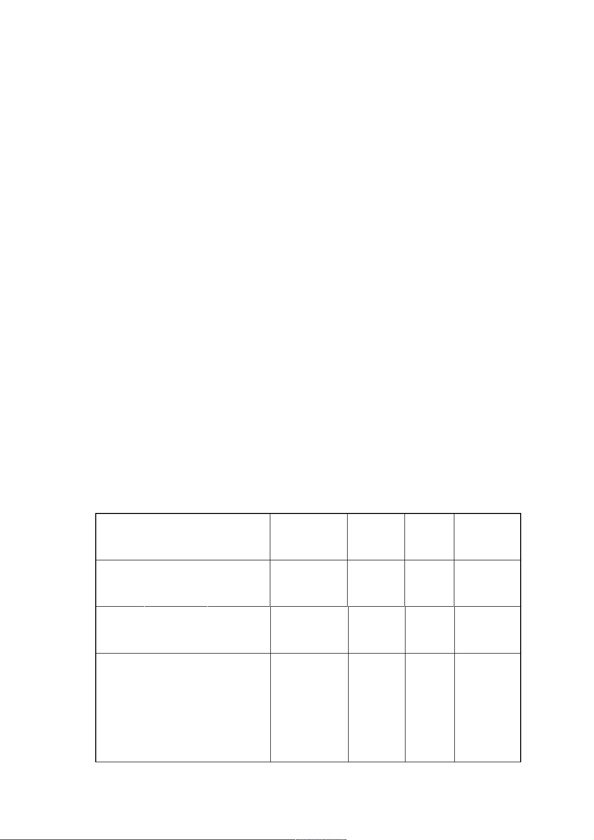
ITEMS LOGO
1 CHN-1CH 49.75MHz
2 WE-6CH 182.25MHz
3 CHN-12CH 216.25MHz
4 CHN-13CH 471.25MHz
PICTURE
CARRIER
PATTERN SYSTEM
PHILIPS
PATTERN
RED
PATTERN
GREY SCALE
/COLOR BAR
CROSS
HATCH
PATTERN
PAL-I 1KHz
PAL-B/G
SECAM-
D/K
PAL-D/K 1KHz
SOUND
MODE
L: --------
R:400Hz
SWEEP
SOUND
REMARK
STEREO/
TELETEXT
Page 4

5 USA-33CH 585.25MHz COLOR BAR NTSC-M --------
WITHOUT
SOUND
CARRIER
6 -------- 751.25MHz
7 -------- 85.25MHz
8 WE-S20CH 294.25MHz
MONOSCOPE
PATTERN
GREY SCALE
/COLOR BAR
Semi-COLOR
4. CHASSIS ALIGNMENT
4-1. Synchronization demodulation Adjustment
a. Connection Diagram (Fig.1)
BAR
3
PAL-I
SECAM-L’ 1KHz SYS-2
PAL-B/G
SWEEP
SOUND
A:400Hz
B:1KHz
DOUBLE
SOUND
CARRIER
Page 5

Fig.1
TUNER
MAIN CHASSIS
IF
C113
16V
+
+ - -
Q102
C625
b. Pattern generator outputs 38MHz color bar PAL D/K Signal with 84dBuV-output level.
c. Pattern Generator output the signal to TUNER IF output terminal through a 0.01UF/63V
capacitor.
d. Connect Digital voltage meter positive terminal to C113 positive pole and negative terminal to
negative pole.
e. DC Regulated power supply applies a +16V DC to C625.
f. Adjust L104 coil to make the pointer displaying on the screen of the Digital voltage meter
move slowly at the range between 0V to 7V. Then set it to 4.5V +/-0.1V.
4.2.System NTSC Adjustment
a. DC Regulated power supply output+16V (Shown as fig.1).
b. Tuner IF output terminal connects to sweep signal generator set at 31.5MHz, 32.5MHz,
33.57MHz, 38.00MHz,
39.50MHz. Connect sweep signal generator probe to pin “B” of Q102.
c. Adjust L102 coil to obtain waveform as following. (Fig.2)
32.5MHz THE LOWEST POINT
(Fig.2)
Page 6

4
4-3. AGC alignment
a. Receive 62dBuV +/-2dB signal. Connect Digital voltmeter positive terminal to tuner AGC
terminal and negative terminal to GND. Switch on power switch
b. Adjust VR101 to obtain RF.AGC just active and the voltage about 6~8V reading at the
Digital Voltage meter reading.
After adjusting well, there should be no confusion on picture at 60dBuV and no distortion
c.
under 100dBuV.
4.4.Chassis Main Power Check-up
a. Add 220V AC to CN601 and switch on power switch.
b
b. Connect digital voltage meter between C618 two terminals.
c. Digital Voltage meter reading should be 140V+/-0.5V. (The voltage will have a little
difference when
use difference type of CRT.)
4.5.NICAM adjustment
Receive a cross hatch Pattern with 86dBuV RF output level.
a.
Connect oscilloscope to C919 one terminal near IC901.
b.
Adjust L901 coil to obtain picture and then get the clearest picture.
c.
5. COMPLETE MACHINE GENERAL ADJUSTMENT
5-1. Screen Voltage check-up
a. Press (P.P) button to set TV at “STANDARD” mode and press the TV/AV to switch
to AV mode.
a. Connect Digital Voltage meter to CRT red cathode (gun) and GND. The reading should
be 140VDC +/-1V reading.
(
The voltage will have a litter difference when use difference type CRT.)
5-2. GO to factory mode
b. Switch off the TV set.
c. Press and hold on both of TV/AV and MENU button on TV Panel at the same time and
then switch on the Main Power. Continuous hold on the TVAV and MEMU button until
the TV will go to factory mode and displayed the “ Vertical Amp. 50 / 60” OSD.
d. Press (P.P) button on remote handset to save and exit factory mode.
5.3.Focus Adjustment.
a. Receive monoscope pattern with 86dBuV RF level. Set TV to “DYNAMIC” mode by
(P.P) button.
b. Adjust the focus knob of FBT to get a most clear picture.
5.4.White Balance Adjustment
a. Receive black & white pattern (PAL system).
Page 7
e.
Press (P.P) button to set TV at “STANDARD” mode, Adjust brightness and contrast
to get 2cd/m2 at low brightness and 85cd/m
reading from CRT color analyzer. Go to factory mode. Make White Balance instrument’
two probes Close up black pattern and white pattern apart.
b. Press remote hand set keys to control the white balance to meet factory requirement.
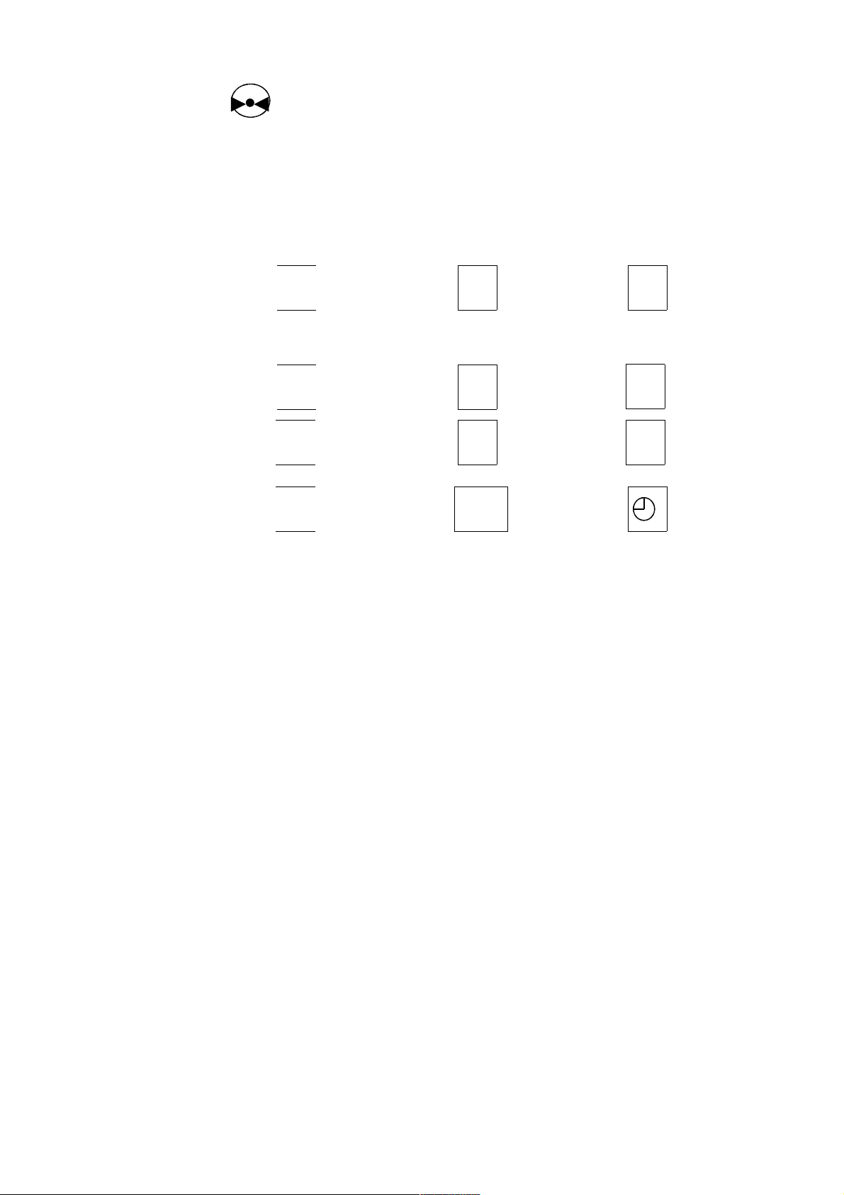
Key’s function refers to the following table.(Fig.3)
1 2 3
+ + +
2
at bright part of black & white pattern
5
RED GAIN GREEN GAIN BLUE GAIN
- - -
4 5
7 8 9
+ + +
DC RED DC GREEN SUB BRIGHT
0 -/--
5.5.Horizontal Center Adjustment
a. 50Hz Horizontal Center Adjustment
Receive 50Hz MONOSCOPE PATTERN with 86dBuV RF output level. Go to factory mode
and select H.PHASE by PROG+/- keys, adjust by VOL+/- keys to obtain picture about
symmetry.
b. 60Hz Horizontal Center Adjustment
Receive NTSC 60Hz MONOSCOPE PATTERN with 86dBuV RF output level. Go to
factory mode and select H.PHASE by PROG+/- keys, adjust by VOL+/- keys to obtain
picture about symmetry.
- - -
(Fig.3)
6
5.6.Horizontal and Vertical Amplitude Adjustment
a.Horizontal Amplitude Adjustment
(1) Receive monoscope pattern with 86dBuV RF output level.
(2) Go to factory mode. Enter horizontal and vertical adjustment MENU by PIC key,
select H1 by PROG+/- keys, and obtain picture good by adjusting VOL+/- keys.
b.Vertical Amplitude Adjustment
(1). 50Hz vertical amplitude adjustment
(a). Receive 50Hz monoscope pattern with 86dBuV RF output level.
c
(b). Go to factory mode. Go to horizontal and vertical adjustment (S9306) MENU by PIC
key, select V5 by PROG+/-
d
keys, obtain picture good by adjusting VOL+/- keys.
(2). 60Hz vertical amplitude adjustment
e
(a). Receive NTSC 60Hz monoscope pattern with 86dBuV RF output level.
f
(b). Go to factory mode. Go to horizontal and vertical adjustment (S9306) MENU by PIC
key, select V6 by PROG+/-
Page 8

g
keys, obtain picture good by adjusting VOL+/- keys.
h
Note: All of the “V AMPL, V POSITION ” MENU are not working in this model. It must be using
the horizontal and vertical adjustment (S9306) MENU for alignment.
5-7. SUB-Brightness Adjustment
a. Receive GREY SCALE/COLOR BAR pattern with 86dBuV-output level.
b. Set the TV set to factory mode. Press PROG +/- keys to select SUB-BRIGHT and then
press “MUTE” key.
i
c. Press VOL +/- keys to make the second darkness bar of GREY SCALE loom.
6
5.8 Vertical adjustment, S-correct, pincushion and trapeziform-correct
a.Receive a cross hatch Pattern Signal with 86dBuV-output level.
b.Go to factory mode. Select horizontal and vertical adjustment (S9306) MENU by PIC key.
c.Select V2 by PROG+/- keys. Adjust vertical center by VOL +/- keys.
Select V3 by PROG+/- keys. Adjust S-correct by VOL +/- keys.
Select V4 by PROG+/- keys. Adjust vertical size by VOL +/- keys.
d.Select H2 by PROG+/- keys. Adjust horizontal pincushion by VOL +/- keys.
Select H3 by PROG+/- keys. Adjust horizontal tubbish by VOL +/- keys.
e.Select H4 by PROG+/- keys. Adjust horizontal trapeziform by VOL +/- keys.
5.9Option Code
a.) Receive a cross hatch Pattern Signal with 86dBuV-output level.
b.) Go to factory mode. Select the Option code by “VOL –“ button.
Using four octal digits which can set 12 bits options.
Decimal 5 7 7 7
Octal 1 0 1 1 1 1 1 1 1 1 1 1
meaning a b c d e f g h I j k l
a 0/1 power on last status/power on standby
b 0/1 CHN/ENG menu/English menu only
(Forced to 1 internal in this software date code Nicole3 V1 19991101 or later)
c 0/1 Woofer Disable/Woofer enable
d 0/1 Surround Disable/Enable
e 0/1 MN system Disable/Enable
f 0/1 BG system Disable/Enable
g 0/1 I system Disable/Enable
h 0/1 DK systemDisable/Enable
i 0/1 Chroma 0dB/1=+6dB.
j 0/1 3 AV/2 AV (if there's no 7439, then one AV)
k 0/1 One set DC alignment/two sets DC alignment (SECAM)
l 0/1 TDA7449 OR TDA7439 SELECTION
Note: to be confirm the last 3 digit j to k.
6. COLOUR PURITY and CONVERGENCE ADJUSTMENT
Page 9

1. COLOUR PURITY ADJUSTMENT (See Fig.4)
Purity Magnet
RB-G RB
Magnet Clamper
Static Magnet
BEFORE ANY ADJUSTMENTS DESCRIBED BELOW ARE ATTEMPTED, V-AMPLITUDE, B+
VOLTAGE AND FOCUSING ADJUSTMENT MUST BE COMPLETED.
a. Place the TV receiver facing NORTH or SOUTH.
b. Plug in TV receiver and turn it on.
c. Operate the TV receiver over 30 minutes.
d. Fully degauss the TV receiver by using and external-degaussing coil.
e. Receive a “Cross-Hatch plug circle” pattern and adjust the static convergence control
roughly.
f. Receive Red Pattern.
7
g. Loose the clamp screw of the deflection yoke and pull the deflection yoke towards you.
h. Adjust the clamp screw of the deflection yoke and pull the deflection yoke towards you.
i. Slowly push the deflection yoke toward bell of CRT and set it where a uniform green field
is obtained.
j. Tighten the clamp screw of the deflection yoke.
2. CONVER GENCE ADJUSTMENT (See Fig.4)
a.Receive a dotted pattern.
b.Unfix the convergence magnet clamper and align red with blue dots at the center of the
screen by rotating.
(R, B) static convergence magnets.
c. Align Red/Blue with green dots at the center of the screen by rotating (RB-G) static
convergence magnet.
d.Fix the convergence magnets by turning the clamper.
e.Remove the DY wedges and slightly tilt the deflection yoke horizontally and vertically to
obtain the good
overall convergence.
f. Fix the deflection yoke by wedges.
g.If purity error is found, follow “PURITY ADJUSTMENT” instructions.
(Fig.4)
Page 10

8
 Loading...