

Datasheet CHFP6KE60A, CHFP6KE60, CHFP6KE43A, CHFP6KE43, CHFP6KE40A Datasheet (Microsemi Corporation)
...Page 1
8700 E. Thomas Road
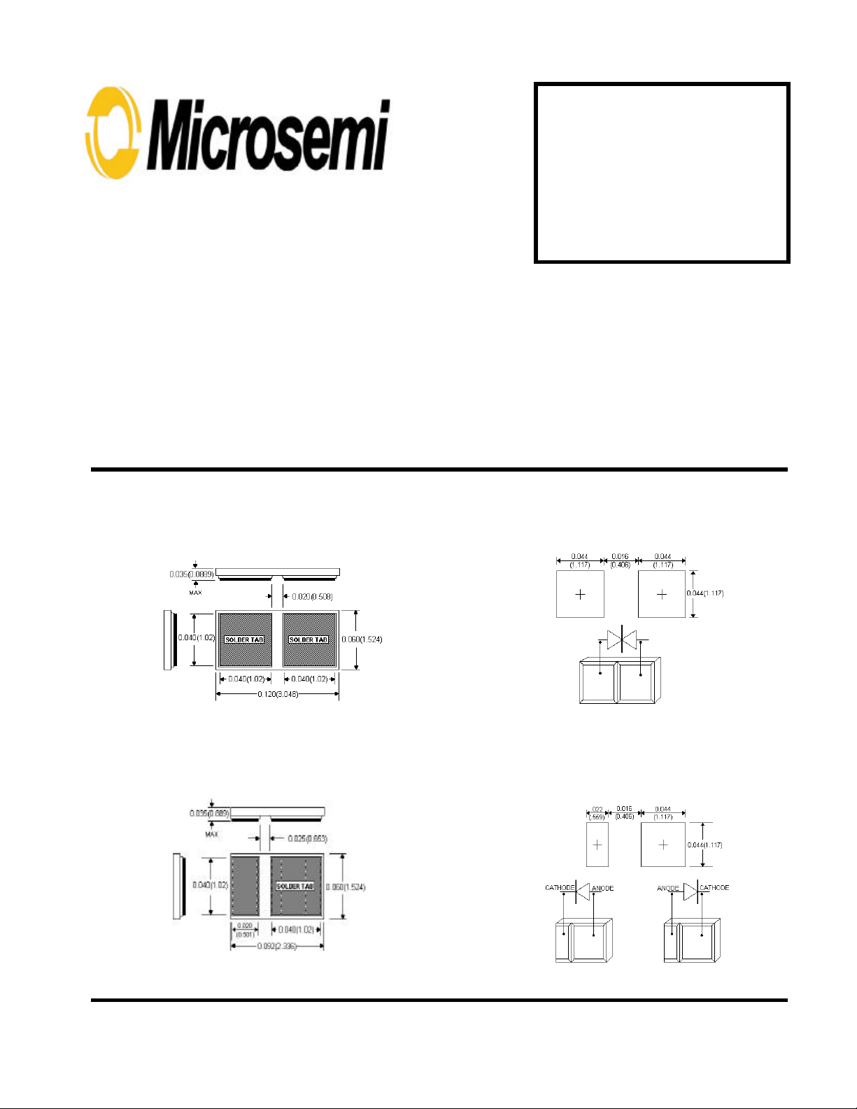
• Solderable standoff tabs .040X.040X.010
Scottsdale, AZ 85251
Tel: (480) 941-6300
Fax: (480) 947-1503
FLIP-CHIP TVS DIODES
CHFP6KE5.0
thru
CHFP6KE170CA
FEATURES
• Unidirectional and Bidirectional
• Fully glass passivated
• 600 watt (10/1000 µs)
• Eliminates wire bonding
• NON Inductive Insertion
• No voltage overshoot
MECHANICAL
•
Weight: 0.01 grams (approximate)
PACKAGING
• Waffle package 50 pices or wafer ring 70 pieces
BIDIRECTIONAL ALL DIMENSIONS NOMINAL
FLIP-CHIP DIMENSIONS PAD SIZE & CIRCUIT
Patented Flip-Chip Series
MAXIMUM RATINGS
• Max Junction Temperature: 1500C (with conformal coating)
• Storage Temperature: -55
• Flip-Chip Peak Pulse Power: 600 Watts (10/1000 µs)
• Maximum non-repetitive peak power 600 Watts (10/1000 µs)
• Total continuous power dissipation 2.5 W (with adequate heat
sink @ 75
• Turn-on time (theoretical) unidirectional 1X10
• Turn-on time (theoretical) bidirectional 1X10
0
C)
inches (mm)
0
C to +1500C
-12
-9
FLIP-CHIP DIMENSIONS PAD SIZE & CIRCUIT
MSC1596.PDF ISO 9001 CERTIFIED REV B 3/13/2000
UNIDIRECTIONAL ALL DIMENSIONS NOMINAL
inches (mm)
VBR above 30 V VBR 30V and below
Page 2
CHFP6KE5.0 thru CHFP6KE170CA
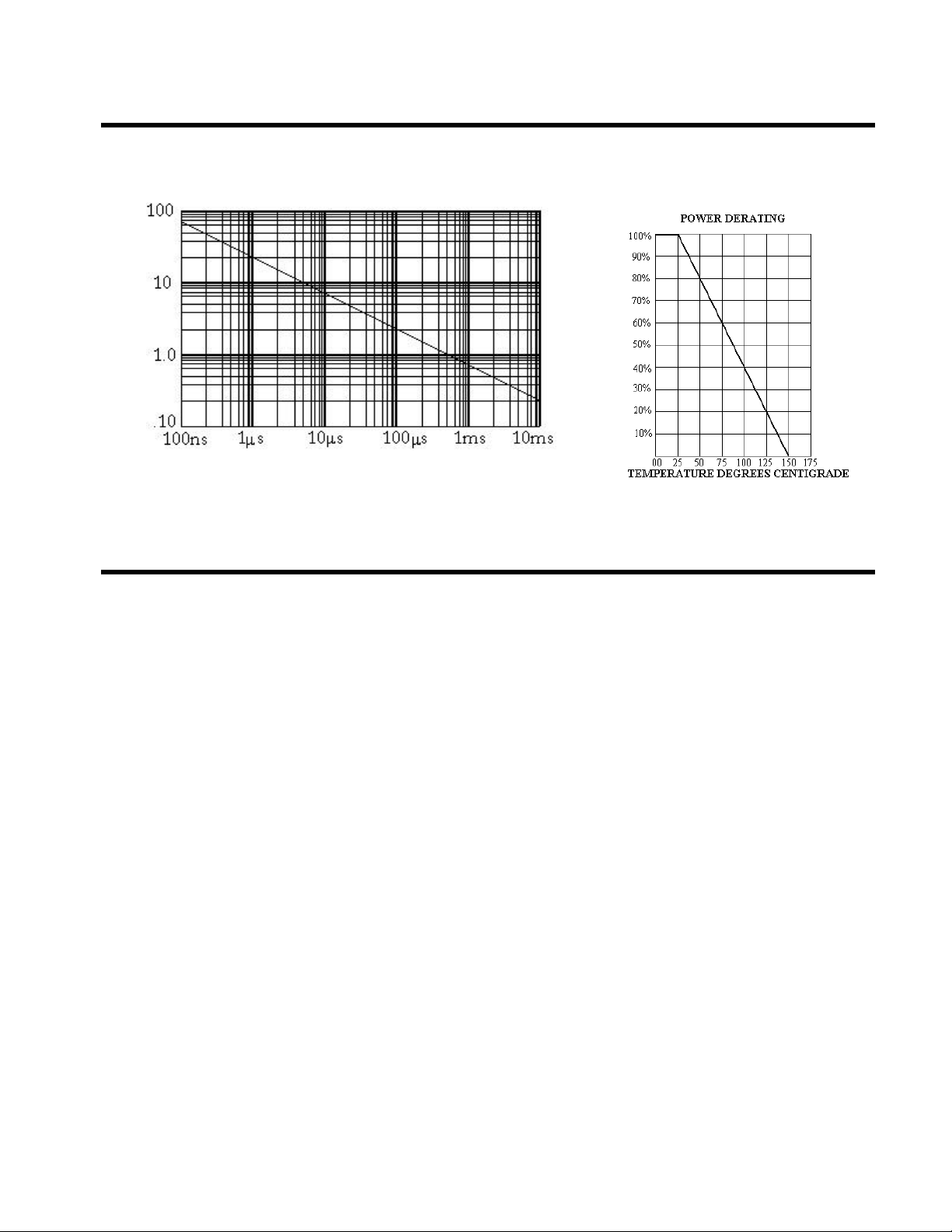
PEAK PULSE POWER Vs PULSE TIME
– PEAK PULSE POWER – kW
pp
P
TP – PULSE TIME – SEC
PEAK PULSE
POWER DERATING
)
PP
) or Current (I
PP
In percent of 25° C rating
Peak Pulse Power (P
TEMPERATURE °C
ATTACHMENT AND CONFORMAL COATING
INSTRUCTIONS
FOR Flip-Chip COMPONENTS
The .010” thick tab standoffs minimize shorting during attachment; however, minimal
solder/conductive epoxy must be used and carefully controlled to prevent excess
attachment material from wicking up the side of the tab and shorting across the junction.
Maximum recommended solder temperatures are 212 C for IR reflow and 221 C for
vapor-phase reflow. For flip-chip protection, coating material is Stycast ™ 2651-40 lowviscosity epoxy manufactured by Emerson & Cuming. Follow instructions carefully for
preparation of the epoxy to prevent entrapment of air bubbles. Make sure that Flip-Chips
have been baked at 100 C for 15 minutes minimum to out-gas any adsorbed moisture
immediately prior to coating. Epoxy-coating material should be dispensed around the
edges of the chip with an appropriately sized syringe after which epoxy is de-aired to
remove bubbles entrapped beneath the chip. Cure epoxy as instructed by the supplier.
MSC1596.PDF ISO 9001 CERTIFIED REV B 3/13/2000
Page 3

CHFP6KE5.0 thru CHFP6KE170CA
ELECTRICAL Characteristics @ 250C Unless otherwise specified
Part
Number
CHFP6KE5.0 5.0 6.4 10 9.6 800 62.5 .057
CHFP6KE5.0A 5.0 6.4 10 9.2 800 62.5 .057
CHFP6KE6.0 6.0 6.67 10 11.4 800 52.6 .059
CHFP6KE6.0A 6.0 6.67 10 10.3 800 58.3 .059
CHFP6KE6.5 6.5 7.22 10 12.3 500 48.7 .061
CHFP6KE6.5A 6.5 7.22 10 11.2 500 53.6 .061
CHFP6KE7.0 7.0 7.78 10 13.3 200 45.1 .065
CHFP6KE7.0A 7.0 7.78 10 12.0 200 50.0 .065
CHFP6KE7.5 7.5 8.33 1 14.3 100 42.0 .067
CHFP6KE7.5A 7.5 8.33 1 12.9 100 46.5 .067
CHFP6KE8.0 8.0 8.89 1 15.0 50 40.0 .070
CHFP6KE8.0A 8.0 8.89 1 13.6 50 44.1 .070
CHFP6KE8.5 8.5 9.44 1 15.9 10 37.7 .073
CHFP6KE8.5A 8.5 9.44 1 14.4 10 41.7 .073
CHFP6KE9.0 9.0 10.0 1 16.9 5 35.5 .076
CHFP6KE9.0A 9.0 10.0 1 15.4 5 59.0 .076
CHFP6KE10 10 11.1 1 18.8 5 31.9 .078
CHFP6KE10A 10 11.1 1 17.0 5 35.3 .078
CHFP6KE11 11 12.2 1 20.1 5 29.9 .081
CHFP6KE11A 11 12.2 1 18.2 5 33.0 .081
CHFP6KE12 12 13.3 1 22.0 5 27.3 .082
CHFP6KE12A 12 13.3 1 19.9 5 30.2 .082
CHFP6KE13 13 14.4 1 23.8 5 25.2 .084
CHFP6KE13A 13 14.4 1 21.5 5 27.9 .084
CHFP6KE14 14 15.6 1 25.8 5 23.3 .086
CHFP6KE14A 14 15.6 1 23.2 5 25.8 .086
CHFP6KE15 15 16.7 1 26.9 5 22.3 .087
CHFP6KE15A 15 16.7 1 24.4 5 24.0 .087
CHFP6KE16 16 17.8 1 28.8 5 20.8 .088
CHFP6KE16A 16 17.8 1 26.0 5 23.1 .088
CHFP6KE17 17 18.9 1 30.5 5 29.7 .090
CHFP6KE17A 17 18.9 1 27.6 5 21.7 .090
CHFP6KE18 18 20.0 1 32.2 5 18.6 .092
CHFP6KE18A 18 20.0 1 29.2 5 20.5 .092
CHFP6KE20 20 22.2 1 35.8 5 16.7 .093
CHFP6KE20A 20 22.2 1 32.4 5 18.5 .093
CHFP6KE22 22 24.4 1 39.4 5 15.2 .094
CHFP6KE22A 22 24.4 1 35.5 5 16.9 .094
CHFP6KE24 24 26.7 1 43.0 5 14.0 .096
CHFP6KE24A 24 26.7 1 38.9 5 15.4 .096
CHFP6KE26 26 28.9 1 46.6 5 12.4 .097
CHFP6KE26A 26 28.9 1 42.1 5 14.2 .097
CHFP6KE28 28 31.1 1 50.0 5 12.0 .098
CHFP6KE28A 28 31.1 1 45.4 5 13.2 .098
CHFP6KE30 30 33.3 1 53.5 5 11.2 .099
CHFP6KE30A 30 33.3 1 48.4 5 12.4 .099
CHFP6KE33 33 36.7 1 59.0 5 10.2 .100
CHFP6KE33A 33 36.7 1 53.3 5 11.3 .100
CHFP6KE36 36 40.0 1 64.3 5 9.3 .101
CHFP6KE36A 36 40.0 1 58.1 5 10.3 .101
CHFP6KE40 40 44.4 1 71.4 5 8.4 .101
CHFP6KE40A 40 44.4 1 64.5 5 9.3 .101
CHFP6KE43 43 47.8 1 76.7 5 7.8 .102
CHFP6KE43A 43 47.8 1 69.4 5 8.6 .102
CHFP6KE45 45 50.0 1 80.3 5 7.5 .102
CHFP6KE45A 45 50.0 1 72.7 5 8.3 .102
CHFP6KE48 48 53.3 1 85.5 5 7.0 .103
CHFP6KE48A 48 53.3 1 77.4 5 7.7 .103
CHFP6KE51 51 56.7 1 91.1 5 6.6 .103
CHFP6KE51A 51 56.7 1 82.4 5 7.3 .103
CHFP6KE54 54 60.0 1 96.3 5 6.2 .104
CHFP6KE54A 54 60.0 1 87.1 5 6.9 .104
CHFP6KE58 58 64.4 1 103 5 5.8 .104
CHFP6KE58A 58 64.4 1 93.6 5 6.4 .104
CHFP6KE60 60 66.7 1 107 5 5.6 .104
CHFP6KE60A 60 66.7 1 96.8 5 6.2 .104
CHFP6KE64 64 71.1 1 114 5 5.3 .105
CHFP6KE64A 64 71.1 1 103 5 5.8 .105
CHFP6KE70 70 77.8 1 125 5 4.8 .105
CHFP6KE70A 70 77.8 1 113 5 5.3 .105
CHFP6KE75 75 83.3 1 134 5 4.5 .105
CHFP6KE75A 75 83.3 1 121 5 4.9 .105
CHFP6KE78 78 86.7 1 139 5 4.3 .106
CHFP6KE78A 78 86.7 1 126 5 4.7 .106
CHFP6KE85 85 94.4 1 151 5 3.9 .107
CHFP6KE85A 85 94.4 1 137 5 4.4 .107
CHFP6KE90 90 100 1 160 5 3.8 .107
CHFP6KE90A 90 100 1 146 5 4.1 .107
CHFP6KE100 100 111 1 179 5 3.4 .107
CHFP6KE100A 100 111 1 162 5 3.7 .107
CHFP6KE110 110 122 1 196 5 3.0 .108
CHFP6KE110A 110 122 1 177 5 3.4 .108
CHFP6KE120 120 133 1 214 5 2.8 .108
CHFP6KE120A 120 133 1 193 5 3.1 .108
CHFP6KE130 130 144 1 231 5 2.6 .108
CHFP6KE130A 130 144 1 209 5 2.9 .108
CHFP6KE150 150 167 1 268 5 2.2 .108
CHFP6KE150A 150 167 1 243 5 2.5 .108
CHFP6KE160 160 178 1 287 5 2.1 .108
CHFP6KE160A 160 178 1 259 5 2.3 .108
Rated
Stand-off
Voltage
V
WM
VOLTS VOLTS mA VOLTS µ A AMPS %/°C
Minimum
Breakdown Voltage
V(
) @I
BR
T
Maximum Clamping
@ I
PP
VC Max
Maximum Reverse
Leakage
@ V
WM
I
D
Rated Maximum
Peak Pulse
Current
I
PP
Maximum Voltage
Temperature
Coefficient
OF V(
BR
)
Note:
For bidirectional devices
add a “C” (example
CHFP6KE5.0C thru
CHFP6KE170CA
bidirectional devices).
are
TOLERANCES
A suffix designates 5%
Plain suffix designates
10%
MSC1596.PDF ISO 9001 CERTIFIED REV B 3/13/2000
 Loading...