

Page 1

HIGH SPEED INTERNET MODEM FAMILY
CH2124 - Send/Retrieve Email. 2 I/O Ports 2400bps.
CH2160 - Send/Retrieve Email. 2 I/O Ports, V.90.
CH2165 - Send/Retrieve Email. Unlimited Email, V.90
2003 Cermetek Microelectronics, Inc. Page 1 Document No. 607-0017 Revision H2 (11/03)
FEATURES
• Replaces conventional modems using the world
wide web for communication.
• Transparent internet operations of Point-to-Point
Protocol (PPP), Password Authentication Protocol
(PAP) and Challenge Authentication Protocol
(CHAP) to connect to the Internet.
• Built-in TCP/IP and SMTP to send emails, TCP/IP
and POP3 to retrieve and/or delete emails.
• On Demand and I/O pin event driven email
transmission and retrieval.
• Send/Retrieve streaming email of unlimited length;
or pre-stored email up to 5M bytes in RAM
(CH2165).
• Retrieve multiple messages (CH2165) or select
individual message (CH2124/60).
• Once online CH2165 can stay online and send,
retrieve and/or delete email.
• Programmable using serial interface
(CH2124/60/65).
• Remote programming using PSTN (CH2124/60).
• Resident modem supports: V.90, V.34bis, V.34,
V.22bis, V.22A/B V.23, V.21, Bell 212A and 103,
(depending on model) and can be used in
conventional modem mode.
• Error correcting: V.42 LAPM, MNP 2-4 and MNP10.
• Automatic baud rate adaptability utilizing speed
sensing, flow control and data buffers.
• Serial interface, V.24 (EIA 232-E), 5 volts.
• NVRAM for stored modem (S-Registers) profiles.
• Cermetek @T
®
AT-like Commands.
• Built-in DAA with 1500 VAC RMS isolation 2122V
peak surge protection.
• UL 1950 and CSA C22.2 950 (Third Edition) Listed,
reference UL File E104957.
• FCC Part 68 Approved/DOT CSA CS-03 Part I
approvable.
• Pin-for-Pin compatible family.
• +5 Volt operation.
• Small size: 1.35” x 1.97” x 0.55” (nominal).
• Low Cost 2400bps version (CH2124).
• Use with any Non-proprietary commercial or private
ISP.
• Cermetek’s iModem Network ISP has 1000s of
local access numbers world wide.
• Failsafe back up 1-800 access number, auxiliary
and alternative telephone numbers available.
• Low cost iModem Network ISP providing email to
Voice, Fax, and email re-routing services.
• 90 day free trial subscription to iModem Network
ISP provided with each iModem.
INTRODUCTION
Direct machine-to-machine interaction represents the
next logical extension of the internet. Cermetek internet
modem (iModem) products are designed to exploit the
internet to facilitate the utilization of machine-tomachine interactions. Using email, information can
easily be transferred between systems and can be
transmitted/retrieved at will. Internet email provides low
cost, near real time multi-path communication.
Replacing conventional modems and long distance
telephone lines with local access internet connections
reduces fixed asset and maintenance costs, limits
communication expenses and saves money.
USER FRIENDLY INTERFACE LAYER
All Cermetek iModem products contain a user friendly
interface layer that provides the user transparent
access to the internet. This interface layer, consisting
of various @T
®
macro commands, has the look and feel
of conventional modem AT commands. With the @T
®
macro commands the user can direct the iModem to
compose, edit/modify, send, retrieve and delete email
messages. Internet and email activity status is reported
via the iModem’s V.24 (EIA 232-E) serial interface.
COMPARISON OF CH21XX iMODEM DEVICES
The CH2165 represents the next generation in internet
enabled devices. This product provides the user with
unsurpassed command and control capabilities. The
CH2165 communicates asynchronously with the host
controller (via the serial port) and the internet (via the
PSTN connection) simultaneously. Consequently, the
user can intersperse CH2165 specific management
commands with internet commands. Further,
commands can be queued. The CH2165 will also send
or retrieve email messages of virtually unlimited length
by using streaming email techniques. The CH2165 is
ideal for applications where larger data transfers are
required and/or where large amounts of data must be
stored locally on the iModem device.
Page 2

Cermetek Microelectronics, Inc. High Speed Internet Modem Family
2003 Cermetek Microelectronics, Inc. Page 2 Document No. 607-0017 Revision H2 (11/03)
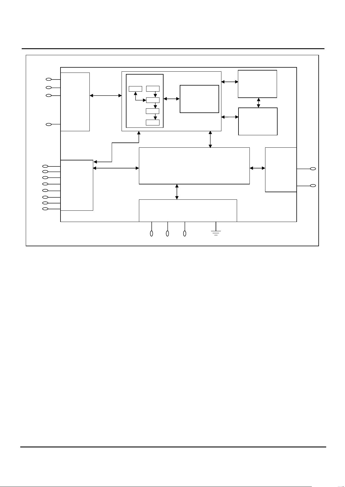
Figure 1. Conceptualized Block Diagram illustrating the Cermetek CH21XX iModem product family
performing the embedded internet application function.
The CH2124/60 products are the first generation
internet enabled devices. These products excel at
sending and retrieving modest amounts of data. Email
messages of approximately 125 ASCII characters in
length can be stored in internal Flash ROM for later
transmission.
The CH2124/60 products are ideal for very low cost
controller applications and in applications where limited
data transfer is required.
OVERVIEW OF THE CH21XX iMODEM
A conceptual representation of the iModem in an
embedded environment is presented in Figure 1. As
can be seen in this figure, the iModem requires the
input of various internet parameters to function
properly: user name, user ID, user password, ISP
telephone number, ISP mail server address/name, local
email address/name, destination email address and
user specified email message/input port status.
Cermetek’s iModem products provide the user with the
ability to assign a unique unit name to each iModem
thereby creating a customized identity for each system
containing an iModem product.
Each iModem device stores the user-supplied
parameters in internal memory. These parameters are
retained when power is removed. The user supplied
parameters are loaded into the iModem via the
iModem’s serial interface port utilizing either
Cermetek’s iNetWizard
®
telecommunications software
package or, alternatively, one of a variety of
commercially available terminal emulation software
packages. iNetWizard
®
is available free of charge and
runs on any standard PC operating Microsoft Windows.
Internet Connectivity. The CH21XX iModem uses the
user supplied parameters to establish an internet
connection and then send, retrieve and/or delete email.
After completion of the required internet activities, the
iModem terminates the internet connection.
Send, Retrieve and Delete Email: CH2165. The
CH2165 has the ability to send and retrieve emails of
virtually unlimited length by employing a technique
referred to as streaming email. Once in streaming
email mode, the user simply continues to supply data to
the CH2165’s serial port, and terminates the data
stream with a <CR>.<CR>. Alternatively, messages of
finite length can pre-stored locally on the CH2165 in
RAM memory and then sent when needed. The data
stream termination sequence for pre-stored messages
is the CTRL D characters.
The total CH2165 RAM memory available to the user is
approximately 5M bytes. For messages that need to be
stored semi-permanently, the user has access of up to
1M byte of Flash ROM for message storage.
Messages stored in ROM can also be sent when
needed.
When retrieving emails, the user continues to save the
data streaming out of the CH2165’s serial port until a
<CR>.<CR> is received.
Refer to Cermetek Application Note # 325, @T
®
Command Set Description and Usage For CH2165
iModem, for more details.
• User Name
• Password
• ISP Telephone Number
• Mail Server Address/Name
• Local Email Address
• Destination Email Address
• User Specified Email
Message/Input Port Status
• User ID
User Supplied Parameters
•
Send email
• Retrieve email
• Delete email
CH21XX
iModem
Product
Family
Internet
(PPP, SMTP, TCP/IP,
POP3)
Page 3

Cermetek Microelectronics, Inc. High Speed Internet Modem Family
2003 Cermetek Microelectronics, Inc. Page 3 Document No. 607-0017 Revision H2 (11/03)
Send, Retrieve and Delete Email: CH2124/60. The
CH2124/60 products send and retrieve email of modest
length. The pre-stored message length is approximately
125 ASCII characters. Messages are stored in Flash
ROM. Streaming email is not supported in the
CH2124/60 iModem products.
Refer to Cermetek Application Note # 155, @T
®
Command Set Description and Usage For CH2124/60
iModems, for more details.
iModem Hardware Configuration. Each CH2160/65
(CH2124) iModem contains a fully functional 56kbps
(2400bps) modem and the hardware and firmware
needed to provide the internet capability. Because of
the unique architecture of Cermetek iModems, these
iModems have the ability to operate as either an
internet email transceiver or as a high reliability analog
modem. Additionally, the CH2124/60 products support
user remote access which can be used to reprogram or
reconfigure an iModem deployed in the field.
The iModem Family of products are pin compatible with
the CH179X and CH2056 modem products. Referring
to Figure 2, the CH21XX iModem Family consists of an
industrial grade high speed modem module and a µP
controller with associated internal logic. The µP
controller and the logic provide all the functions
required for internet communication via standard PSTN
telephones lines. The CH2165 contains an additional 8
Mbytes of RAM and 2 Mbytes of Flash ROM. All
CH21XX iModem products utilize TCP/IP, PPP, PAP,
CHAP, SMTP and POP3 internet protocols.
Required External Connections. The iModem
requires an external RJ-11C jack for the PSTN line
connection. An CCITT V.24 serial interface is required
when host processor control of the iModem is required
in the specific application. All retrieved emails are
presented to the host system for further processing
and/or retention via the serial interface.
Approvals. The CH21XX iModem Family is FCC Part
68 approved, UL 1950 and CSA C22.2 950 (Third
Edition) listed and Canadian DOT CSA CS-03
approvable.
Physical Dimensions. The modules are designed for
PCB through-hole mounting and are 1.35” x 1.97” x
0.55” in size.
iMODEM EVALUATION BOARD
Cermetek manufactures a companion evaluation board
that is designed to simplify the hardware connections
required to program the iModem as well as providing a
reliable platform to assist with system level debugging.
Contact Cermetek and ask for the CH21XX iModem
Evaluation Board.
iMODEM NETWORK ISP
A valid ISP account ID and password are required to
access the internet. As a convenience to our
customers, and to facilitate operational use of the
iModem, Cermetek supplies each iModem with a preprogrammed account on the Cermetek iModem
Network ISP. This account is provided on a 90 day
free trial offer basis. Cermetek established the iModem
Network ISP to provide embedded internet appliance
users with features and services tuned to the unique
demands of the internet appliance environment. In
addition to standard email service, the iModem
Network ISP can provide: email to FAX, email to Voice,
email to dynamic web page update, and email rerouting. Refer to Cermetek Application Note # 149,
Cermetek Internet Service (ISP) Description of
Features and Services, for more details.
The CH2165 can utilize any non-proprietary commercial
or private ISP for internet access as well as the
Cermetek iModem Network ISP. We recommend the
Cermetek iModem Network ISP because of its
machine friendly features and low cost $2.00 per month
access. Please see www.imodem.net
for more details.
iMODEM CONTROL METHODOLOGIES
The iModem receives @T® commands from the host
processor or receives an event status flag on the Send
Email Control Pin (Pin #6 – CH2124/60) and proceeds
to dial up the local POP, log on to the internet,
authenticate and verify the user ID and password, and
either sends or retrieves email depending on the
command/status flag received. For CH2124/60
products, see Table 1 for a summary of available @T
®
commands. For CH2165 products, see Table 2.
The iModem Family offers a variety of internet
communication features ranging from simple on
demand event triggered email transmission to full send
and retrieve email capability. User Control of the
internet communication activity of the iModem device
typically falls into one of the following basic control
strategies:
1. Fully Autonomous or event driven pin control
requiring no host processor intervention. A prestored message is sent on a pin transition
(CH2124/60).
2. Semiautonomous control, requiring one command to
be issued from the host processor. A pre-stored
message is sent on command.
3. Complete host intervention and supervision requiring
each command to be issued from the host.
Message is constructed and sent in real time.
Page 4
Cermetek Microelectronics, Inc. High Speed Internet Modem Family
2003 Cermetek Microelectronics, Inc. Page 4 Document No. 607-0017 Revision H2 (11/03)
Figure 2. Functional Block Diagram of Cermetek CH21XX iModem Products. Note the additional RAM and ROM
provided in the CH2165 iModem product.
Fully Autonomous On Demand Event Driven
Control: CH2124/60. This is the simplest method of
operational control. Application of a 50ms TTL Low
going pulse or level to the Send Email Control pin (Pin
# 6) will cause the CH2124/60 iModem to send an
email using its internal internet configuration profile.
This profile is pre-programmed at the factory and can
be modified by the user as necessary. No host
processor intervention is required. The DTE serial
interface is not required for fully autonomous on
demand or event driven control. The CH2124/60
iModem will abort email related activities and return to
the idle state if a low going TTL pulse is presented to
the SEND Email Control Pin (Pin # 6) at any time during
or after initiation of email send.
Semi-Autonomous Control: CH2124/60. This method
requires a minimal amount of host processor
intervention and requires that the DTE serial port be
operational. Semi-autonomous control is a special
case of full Host Supervised Control and relies on the
preprogrammed default internet configuration profile
contained within the iModem. Initiation of an email
activity occurs with the issuance by the host processor
to the iModem the appropriate @T
®
command to
send/retrieve/delete email. PSTN dial-up, logon,
authentication and email transmission, retrieval, and/or
deletion are performed automatically by the iModem in
the same fashion as for the Fully Autonomous OnDemand control method described above.
Host Supervised Control: CH2124/60. This method is
the most flexible, but requires issuance by the host
processor of the necessary @T
®
commands in the
required order from the host processor. When
choosing an implementation scheme utilizing a host
processor, the host controls the iModem by using
Cermetek @T
®
commands. These commands are
similar to the standard Hayes AT command set.
Although the DTE serial port is required to be
operational for this method of control, an additional
feature of this method is the ability of the host to override the preprogrammed parameters (including the
email message content) by simply entering the
applicable information using the appropriate @T
®
Command.
Delete Email: CH2124/60. The user may selectively
delete any email message (by specifying the message
number) or delete all messages cached on the POP3
server.
PSTN
Input 1
Input 2
SEND EMAIL
CONTROL
PIN
INPUT
SENSE
AND
OUTPUT
PINS
Interface
Circuitry
SERIAL
INTERFACE
V-24
EIA-232-E or
UART
MODEM
V.90 (CH2160/65)
V.22bis (CH2124)
MODEM INTERFACE
DAA
CH21XX
RXD
RTS
DCD
DSR
RI
CTS
TXD
DTR
TIP
Ring
EMAIL
ACCEPTED
INDICATOR
PIN
Flash ROM
32Kx8
(CH2124/60)
Network
Protocol
SMTP
TCP
IP
PPP
POP 3
µ
P
RST
SPK
+5V
GND
Flash ROM
2Mx8
(CH2165)
RAM
8Mx8
(CH2165)
Page 5

Cermetek Microelectronics, Inc. High Speed Internet Modem Family
2003 Cermetek Microelectronics, Inc. Page 5 Document No. 607-0017 Revision H2 (11/03)
Email and Internet Activity Status: CH2124/60. The
CH2124/60 provides activity status messages on the
iModem’s serial port. These status messages consist
of a series of ASCII characters. Some examples are:
BAD MESSAGE NUMBER, CONNECT, HANGING UP,
MESSAGE ACCEPTED, MESSAGE DELETED. For a
more detailed discussion of CH2124/60 status
messages, refer to Cermetek Application Note # 155,
@T
®
Command Set Description and Usage For
CH2124/60 iModems.
Send Email: CH2165. To send email messages, the
user must explicitly open the TCP socket connection
using the @TCP command. This command
automatically dials the specified local access POP
phone number, performs user authentication,
establishes a PPP connection and obtains an IP
address.
Once connected to the internet, the user may use one
of two methods to send email messages: use prestored messages contained in resident memory or use
streaming messages obtained in real-time from the
CH2165’s DTE serial I/O port. In either case, multiple
email destination addresses are allowed.
For the case of pre-stored messages, each message is
associated with a user defined message name. The
user enters the @TD=msgname command (where
msgname is the message file name) and the CH2165
sends the email using the SMTP protocol.
For the case of streaming email, the user enters the
@TD=0 command (where 0 is a reserved name and
signals the CH2165 that streaming email is desired).
The CH2165 then sends the appropriate SMTP email
headers and prompts the user to supply the body of the
message. The user presents as many ASCII
characters as desired to the CH2165’s DTE serial port.
When finished, the user must end the streaming input
with a <CR>.<CR>. The CH2165 will then terminate
the SMTP message and close the SMTP connection. If
the SMTP inactivity timer limit is exceeded (currently
set at 90 seconds), the CH2165 will automatically
terminate the message and close the SMTP
connection. To end the internet session, the user must
explicitly close the TCP connection and terminate the
PSTN dial-up phone call by entering the @TCT
command.
When using pre-stored messages in resident memory,
the user is responsible for message memory
management and utilization. Exceeding the memory
limits will cause memory wrap around and messages
may become lost or corrupted.
Retrieve Email: CH2165. The CH2165 will retrieve
email from POP3 servers complying with applicable
internet governing RFCs. By executing the @TES
command, the user may obtain an inventory listing
containing Subject Line and Message Number of all
messages currently cached on the POP3 server. The
user may selectively down load individual messages
(by message number) or may retrieve all messages on
the server. Messages retrieved are provided to the
user on the iModem’s serial port and are not stored in
CH2165 resident memory.
Delete Email: CH2165. The user may selectively
delete any email message (by message number) or all
messages cached on the POP3 server.
Email and Internet Activity Status: CH2165.
Currently, the CH2165 provides two levels of internet
and email status information. Using the @TCS=PPP
command, the user can monitor all the internet PPP
communication. Additionally, the user can determine
internet connectivity status by issuing the @TCS=PING
command. The @TCS=PING command causes the
iModem to send four successive PING commands
directly to the internet host. Responses from the host
include Host IP address and connectivity information.
Back-up and Alternative POP access Phone
Numbers. Cermetek iModem products allow usage of
an alternative local access POP phone number or, if
available, a 1-800 number, should the iModem fail to
connect to the primary POP. The user can establish
the number of attempts made to the primary POP
before the back up POP is attempted.
DESCRIPTION OF FUNCTIONAL BLOCKS AND
DISCUSSION OF BASIC OPERATIONS
Each CH21XX iModem product consists of the following
functional blocks:
1. µP controller with Network Protocols and Flash
ROM.
2. Serial interface buffer.
3. Input/Output interface circuitry.
4. Internal modem (V.90 or V.22bis).
5. Modem interface circuitry.
6. DAA (Data Access Arrangement) PSTN interface.
7. Additional Flash ROM (CH2165 only).
8. Additional RAM (CH2165 only).
Figure 2 contains a schematic drawing illustrating the
interconnectivity of the various functional blocks
comprising the CH21XX iModem products.
Each iModem performs the following internet
connectivity functions automatically:
1. Dials local POP and Connects to ISP.
2. Authenticates user ID and logs onto the internet.
3. Sends (or Retrieves) email to (from) the server
address/name specified using the ISP’s SMTP
(POP3) Mail Server.
4. Terminates ISP session after all data is sent (or
retrieved) (CH2124/60 only).
Page 6

Cermetek Microelectronics, Inc. High Speed Internet Modem Family
2003 Cermetek Microelectronics, Inc. Page 6 Document No. 607-0017 Revision H2 (11/03)
5. The CH2124/60 sends an ASCII MESSAGE
ACCEPTED activity response message and sends
a TTL LOW Pulse to Pin 8 indicating that the ISP
Mail Server has accepted the email message.
Control of the internet capabilities of the iModem can be
either event driven or initiated and controlled by a
system level host processor. Refer to Table 3 for a
complete set of pin descriptions.
When not utilized in the internet connectivity role, the
iModem will function as a standard analog modem.
KEY FEATURE
The user has complete control of the level of
autonomy the iModem exercises in the user’s
application. This is a unique feature of Cermetek’s
iModem products.
µP Controller. The µP controller performs the required
internet operations by interpreting each specific @T
®
command and executing the appropriate internet
commands. The necessary internet protocol firmware
is resident in flash ROM. The @T
®
commands function
as an extension to the industry standard Hayes AT
command set.
Internal Modem. The internal modem is used to
establish a data connection with the ISP. The
CH2160/65 contains a V.90 internal modem while the
CH2124 contains a V.22bis internal modem. The
internal modem can be controlled with Hayes AT
commands and is compatible with industry standard
communication software. Refer to Cermetek
publication, AT Commands and S-Registers
, for a more
detailed discussion of the Hayes AT commands
supported by the iModem product family.
When operating in standard analog modem mode, the
maximum Data Terminal Equipment (DTE)/Host system
communication speed is established by the maximum
speed available from the DTE/Host and is not limited by
the iModem product.
IMPORTANT NOTICE
AS DELIVERED FROM THE FACTORY, all @T®
command communication between the CH2160/65
(CH2124) iModem and the host processor is
conducted over the serial interface at 57.6/19.2kbps
(2400bps).
CH21XX DTE Speed. AS DELIVERED FROM THE
FACTORY, the CH2160/65 iModem will only
communicate with the DTE at 57.6/19.2 kbps and the
CH2124 at 2400bps. However, the user may modify
the DTE speed with the appropriate @T
®
commands.
Refer to Application Note # 155, @T
®
Command Set
Description and Usage For CH2124/60 or to Application
Note # 325, @T
®
Command Set Description and Usage
For CH2165. When the user changes the DTE
communication speed to any speed other than the
default value set of the factory, the user must ensure
that the DTE supports the speed selected. Failure to
do so could adversely affect communication with the
iModem device or, worst-case, disable communication
with the internal µP controller. Refer to Application
Note # 158, Cermetek iModem Caveats and Definitions
,
for a more detailed discussion of this issue.
Refer to Cermetek’s High Speed Modem and FAX
Family product data sheet for a complete Description of
the internal modem’s capabilities and functions.
Serial Host Interface Buffer. The iModem utilizes a
serial V.24 EIA 232-E 5V interface to communicate with
the internal modem and to communicate with the
internal µP.
Telephone Line Interface or DAA. The iModem
family includes a unique low distortion DAA designed
for optimal performance over all PSTN line conditions
thereby achieving the most reliable and best
performance PSTN connections.
The CH21XX iModem family is designed to meet North
American telephone standards as set by FCC Part 68
IMPORTANT NOTICE
If the user wants to change the DTE/Host
communication speed to any speed other than the
factory set speed of 57.6/19.2kbps for the CH2160/65
or 2400bps for the CH2124, the user must first
change the DTE speed of the iModem using the
appropriate all @T® commands before changing the
DTE/Host speed. Refer to Application Note # 158,
Cermetek iModem Caveats and Definitions, for a
more detailed discussion of this issue.
(USA) and CSA CS-03 Part I (Canada). Each iModem
product is shipped from the factory with an FCC label
indicating the FCC registration number and ringer
equivalent. The PSTN line interface is UL1950 and
CSA listed. Consequently, the iModem family of
products satisfies U.S. and Canadian requirements,
and will meet other international approval agency
requirements that specify these levels of isolation.
Page 7

Cermetek Microelectronics, Inc. High Speed Internet Modem Family
2003 Cermetek Microelectronics, Inc. Page 7 Document No. 607-0017 Revision H2 (11/03)
Table 1. Summary of Available @T Commands For CH2124/60
Command Query Description/Function
Commands To Set and Query iModem Parameters
A1 A1? Set destination address.
D --- Dial ISP, Send Input Port Status.
DG --- Dial ISP, retrieve email.
DK --- Dial ISP, delete email.
DM1 --- Dial ISP, send User Defined email message.
E1 E1? Set “FROM” address.
H --- Initiate hang-up sequence.
--- K? Display all K parameters.
K0 --- Select CHAP and /or PAP.
K1 --- Set number of redial attempts for auto-redial.
K2 --- Set number minutes between redial attempts.
K3 --- Set number of Message Accepted required to exit auto-redial.
K4 --- Select ISP login method.
K5 --- Enable/Disable FailSafeTM Back Channel.
K8 --- Select Email message type to be sent when SEND pin is TTL Low.
K10 --- Select DTE Baud Rate
K11 --- Enable/Disable Remote Dial-Up Access.
L1 L1? Set user name.
M1 M1? Set User Defined email message.
N1 N1? Set local access POP phone number.
OP1 OP1? Set POP3 server IP address.
OS1 OS1? Set SMTP server IP address.
PW PW? Set Dial-up password.
PM PM? Set POP3 password.
P1 P1? Set ISP password.
Q --- Terminate iModem Mode of remotely accessing iModem unit.
S1 S1? Set email subject.
U1 U1? Set email recipient “TO” name.
Z0 --- Restores factory profile.
Z1 --- Restore FailSafeTM Back Channel profile.
Commands To Interrogate iModem
Command Function
TI Display iModem product type and firmware revision.
TV Displays ISP configuration profile and User Defined email message.
TV0 Displays ISP configuration profile and User Defined email message.
TV1 Displays Input Port Status message.
Note: Most commands that set iModem parameters will also serve the query function by appending a ? to the
command. Example: @TS1?<CR> will return the email subject line text.
Page 8

Cermetek Microelectronics, Inc. High Speed Internet Modem Family
2003 Cermetek Microelectronics, Inc. Page 8 Document No. 607-0017 Revision H2 (11/03)
Table 2. Summary of Available @T® Commands By Category for CH2165.
Command Query Description
Email Message Management
@T[M][=n] @T[M][?] Enter email message, n. Length limited 100K bytes per message. All valid ASCIII
characters allowed. Use CNTRL D to terminate message entry. Message is
maintained in dynamic RAM until stored in Static Memory using the @TW command.
Send Email Message
@T[D][=n] ----- Dialup ISP and send email message, n. Use internet TO, FROM, REPLY, and
ERROR TO addresses contained within message n. Use the POP dialup phone
number currently active.
@T[D][=0] ----- Dialup ISP. Use internet TO, FROM, REPLY, and ERROR TO addresses currently
active. Use the POP dialup phone number currently active. Enter Streaming Email
data entry mode. Terminate data entry using <CR>.<CR>. Message is sent
immediately following receipt of <CR>.<CR> sequence.
POP Access Dialup Phone Number
@T[N][=n] @T[N][?]
Set POP dialup access dial-up phone number string, n. Special characters
supported:
Each comma will cause a 2 second delay.
Use a dash as a delimiter. Dashes are ignored.
Password
@T[PI][=n] @T[PI][?] Set ISP Login password, n.
@T[PM][=n] @T[PM][?] Set POP3 email retrieve password, n.
Username
@T[UI][=n] @T[UI][?] Set ISP Login username, n.
@T[UM][=n] @T[UM][?] Set POP3 email retrieve username, n.
POP3 Retrieval
@T[ED][=n] ----- Delete message number, n.
@T[EO][] ----- Open POP3 mailbox.
@T[EQ][] ----- Quit POP3 mailbox activity and close POP3 server.
@T[ER][=n] ----- Retrieve message number, n.
@T[ES][] ----- Inventory all messages currently on POP3 server and list message number and
subject line.
DCE and DTE Attributes
@T[BC][=n] @T[BC][?] Select DCE Baud rate, n. Allowable values:
n=57600.
n=38400.
n=19200.
n=9600.
n=4800.
n=2400.
By default, if no value is specified, the CH2165 will automatically determine the
maximum baud rate supported by the PSTN connection. This is referred to as auto-
bauding.
@T[BE][=n] @T[BE][?] Toggle DTE echo.
n=on Enable DTE echo (default).
n=off Disable DTE echo.
@T[BT][=n] @T[BT][?] Select DTE Baud rate, n. Allowable values:
n=57600.
n=38400.
n=19200. (Default).
n=9600.
n=4800.
n=2400.
Page 9

Cermetek Microelectronics, Inc. High Speed Internet Modem Family
2003 Cermetek Microelectronics, Inc. Page 9 Document No. 607-0017 Revision H2 (11/03)
Table 2. Summary of Available @T® Commands By Category for CH2165 (continued).
Command Query Description
Email Addresses and Email Subject Line
@T[AD][=n] @T[A][?] Set email DESTINATION address, n. This is the address to which the email will be
sent. This is the address that appears in the TCP/IP header.
@T[AE][=n] @T[A][?] Set email ERROR address, n. This is the address to which reply emails will be sent
when an email delivery error is encountered by the SMTP server. This address
becomes the DESTINATION address of the Error Email and appears in the TCP/IP
header.
@T[AF][=n] @T[A][?] Set email FROM: address, n. This is the address that follows the FROM: located in
the body of the email message. The FROM address is the address used by the
POP3 server to retrieve email. By convention, the FROM: address matches the email
sender’s address. However, this is not required for proper delivery of the email
message. This address appears in the TCP/IP header.
@T[AR][=n] @T[A][?] Set email REPLY address, n. This is the address to which reply emails will be sent
when the Email Reply button is selected. This address becomes the DESTINATION
address and appears in the TCP/IP header.
@T[AS][=n] @T[A][?] Set email SUBJECT LINE, n. This is the subject line that appears in the email
message.
@T[AT][=n] @T[A][?] Set email TO: address, n. This is the address that follows the TO: located in the body
of the email message. By convention, the TO: address matches the DESTINATION.
However, this is not required for proper delivery of the email message.
Static RAM Memory Management
@T[W][=n] ----- Store filename, n, in Static RAM memory. Files stored in Static RAM memory will be
retained when power is removed.
Server Addresses
@T[SS][=n] @T[SS][?] Set SMTP server symbolic name, n. This symbolic name is used by the CH2165 to
determine the SMTP server address.
@T[SM][=n] @T[SM][?] Set POP3 server symbolic name, n. This symbolic name is used by the CH2165 to
determine the POP3 server address.
Help Topics
----- @T[H][?] Displays all supported commands. Currently:
A Display Addresses and Subject Line command syntax.
C Display PPP connectivity command syntax.
D Display send email command syntax.
E Display retrieve email command syntax.
I Display IMAP and POP3 email command syntax.
M Display create or view email message command syntax.
N Display local POP access phone number command syntax.
P Display password command syntax.
S Display mail/SMTP server command syntax.
U Display username command syntax.
V Display verbose command syntax.
Z Display factory re-set command syntax.
----- @T[H][?=n] Displays details for specified command, n, and provides an example of command
usage. See supported commands above.
Internet Connectivity Status
@T[CS][=PPP] ----- Displays all PPP connectivity information.
@T[CS][=PING] ----- Sends four successive ping commands to the imodem.net server.
Page 10

Cermetek Microelectronics, Inc. High Speed Internet Modem Family
2003 Cermetek Microelectronics, Inc. Page 10 Document No. 607-0017 Revision H2 (11/03)
Table 2. Summary of Available @T® Commands By Category for CH2165 (continued).
Command Query Description
TCP Management
@T[CP][] ----- Establish TCP connection. This command causes the CH2165 to perform the
following tasks in the order listed:
1. Go Off-Hook and dial POP phone number specified @TN=n command.
2. Connect to internet using Login ISP Username specified by @TUI command and
ISP Login Password specified by @TPI command.
3. Obtain IP address and establish TCP socket connection.
@T[CT][] ----- Terminate TCP connection. This command causes the CH2165 to perform the
following tasks in the order listed:
1. Close TCP socket connection.
2. Disconnect from the internet.
3. Go On-Hook.
Pins 1 and 2 function as both input and output
connections to the PSTN. To maximize field reliability
in hostile environments, to ensure UL compliance, and
also optionally for FCC part 15 compliance, these two
pins may be routed through an external network such
as that briefly described in figure 3 or as described in
more detail in Cermetek Application Note # 126,
Supplemental PSTN Line Protection
.
PHONE LINE CONNECTION GUIDELINES
1. The iModem must be mounted in the final
assembly such that it is isolated from exposure to
any hazardous voltages within the assembly.
Adequate separation and restraint of cables and
cords must be provided.
The circuitry from the iModem to the telephone
interface must be provided in wiring that carries
no other circuitry other than that specifically
allowedin the FCC rules (such as A and A1
leads).
2. Connection to the PSTN line should be made
through an RJ-11C jack.
3. PCB traces from the iModem’s RING and TIP
pins to the RJ-11C jack must be 0.1 inch spacing
or greater to one another and 0.2 inch spacing or
greater to all other traces. The traces should
have a nominal width of 0.020 inches or greater.
4. The RING and TIP PCB traces should be as
short as possible and oriented to prevent
coupling with other high speed or high frequency
signals present on the host circuit PCB.
5. No additional circuitry other than that shown in
Figure 3 may be connected between the iModem
module and the RJ-11C jack. Doing so will
invalidate the conveyed FCC approval.
6. The iModem, the RJ-11C jack, the interfacing
circuitry and all PCB traces must be contained on
a PCB with a 94 V-0 flammability rating.
7. The supplied FCC registration label must be
applied visibly on the outside of the product.
8. The product’s User Manual must provide the user
with instructions for connection and use as
recommended in the FCC Registration Section
below.
CANADIAN APPROVALS
The iModem family is approvable for use by DOT to
CSA CS-03 Part I. However, per Canadian
procedures, approval can only be granted after the
iModem has been installed into the end product.
Typically, Canadian approval is obtained by submitting
the final end product to an independent test house or
consultant for evaluation. The test house/consultant
then forwards the test results and applicable
documents to the regulatory agency. Cermetek offers
a list of consultants to assist with this process.
iMODEM HANDLING AND ASSEMBLY
RECOMMENDATIONS
The iModem contains static-sensitive components and
should only be handled by personnel and in areas that
are properly protected against static discharge.
There are two mounting techniques that are
recommended for physically connecting the iModem to
a PCB:
1. Direct soldering.
2. Sockets.
Direct Soldering. The iModem may be wave
soldered onto a circuit card. All iModem products are
sealed and will not be harmed by industry standard
wave soldering processes.
Page 11

Cermetek Microelectronics, Inc. High Speed Internet Modem Family
2003 Cermetek Microelectronics, Inc. Page 11 Document No. 607-0017 Revision H2 (11/03)
Socketing. The socket approach to mounting
eliminates cleaning and desoldering concerns. When
the socket is used, it must make a solid connection to
all pins. Failure to do so will cause unreliable or
intermittent operation. Also, steps should be taken to
assure that the module remains tightly seated in the
socket after the end product is shipped. Cermetek
recommends the 50 pin strip socket CES-150-01-T-S
by Samtec. Refer to Application Note# 130, Summary
of Recommend Supplies, for a list of supplies and
associated contact information.
FCC REGISTRATION
All CH21XX iModem products are registered with the
FCC under Part 68. To maintain the validity of the
registration, notice of the restrictions the FCC places
on the iModem and its use must be served to the end
user of the product containing the iModem.
In addition to restriction notification, the FCC requires
that Cermetek make all repairs to all products in the
iModem family. If repairs are necessary after
installation of the iModem and the end product has
been delivered to the end user, the end product must
be returned to the end product supplier where the
iModem can be removed and then forwarded to
Cermetek for repair. The following notice is
recommended and should be included in the end
product’s user manual.
FOR YOUR USER’S MANUAL
The Part 68 rules require the following (or equivalent)
be provided to the end user of the equipment
containing an iModem device.
Type of Service: The (insert end product name) is
designed to be used on standard device telephone
lines. It connects to the telephone line by means of a
standard jack called the USOC RJ-11C (or USOC
RJ45S). Connection to telephone-company-provided
coin service (central office implemented systems) is
prohibited. Connection to party lines service is subject
to state tariffs.
Changes in Attestation Procedure for Plugs and
Jacks: (Name of applicant) attests that the network
interface plugs or jacks used on this equipment comply
with and will continue to comply with the mechanical
requirements specified in Part 68, Sub-part F,
specifically the dimensions, tolerances and metallic
plating requirements. The compliance of these
connectors will be assured by purchase specifications
and incoming inspection. Documentation of such
specifications and/or inspections will be provided by
the FCC within 30 days of their request for the same.
Telephone Company Procedure: The goal of the
telephone company is to provide the best service it
can. In order to do this, it may occasionally be
necessary for the telephone company to make
changes to their equipment, operations or procedures.
If these changes might affect service provided to the
users or the operation of the user’s equipment, the
telephone company will give the user notice, in writing,
to allow the users to make any changes necessary to
maintain uninterrupted service.
In certain circumstances, it may be necessary for the
telephone company to request information from the
users concerning the equipment which the user has
connected to the telephone line. Upon request of the
telephone company, provide the FCC registration
number and the ringer equivalence number (REN);
both of these items are listed on the equipment label.
The sum of all of the REN’s on the user’s telephone
lines should be less than five in order to assure proper
service from the telephone company. In some cases,
a sum of five may not be useable on a given line.
Consult your telephone provider.
If Problems Arise: If any of the user’s telephone
equipment is not operating properly, the user should
immediately remove it from the user telephone line, as
it may cause harm to the telephone network. If the
telephone company notes a problem, they may
temporarily discontinue service. When practical, they
will notify the user in advance of this disconnection. If
advance notice is not feasible, the user will be notified
as soon as possible.
When the user is notified, the user will be given the
opportunity to correct the problem and informed of
their right to file a complaint with the FCC. Contact the
local telephone service provider if any questions arise
concerning the telephone service.
In the event repairs are ever needed on the (insert
your product name), they should be performed by
(insert your company name), or an authorized
representative or (insert your company name). For
information contact: (insert your company address).
Page 12

Cermetek Microelectronics, Inc. High Speed Internet Modem Family
2003 Cermetek Microelectronics, Inc. Page 12 Document No. 607-0017 Revision H2 (11/03)
Table 3. iModem Family Pin Description.
PIN NAME I/O FUNCTION
1 RING I/O
Directly connects to the telephone line’s Ring lead through a user supplied RJ-11C jack.
2
TIP
I/O
Directly connects to the telephone line’s TIP lead through a user supplied RJ-11C jack.
3
NC
---
NO CONECTION
4
NC
---
NO CONECTION
5
SPK
O SPEAKER. Audio output for speaker. See speaker control diagram.
6 SEND I
SEND EMAIL. Active Low. A low pulse will send an email. The modem will go off hook,
dialup an ISP, send the email and hang up. The SEND pin must be tied high when not in
use. Pulse should be 50msec minimum.
7
IN 1
I Input. TTL High or Low input pin. The logic level of this input pin is reported in the email
message.
8 SENT O
EMAIL SENT. Active Low. A low pulse is output on this pin to indicate that an email sent
by the iModem has been accepted by its ISP. The pulse is low for 50ms minimum. See
figure 8.
9
IN 2
I Input. TTL High or Low input pin. The logic level of this input pin is reported in the email
message.
10 TXD
I TRANSMIT DATA. Serial transmit data input. Marking, or a binary 1 condition is indicated
by a HIGH.
11 RXD O
RECEIVE DATA. Serial Receive data output. Received marking or a binary 1 condition is
indicated by a HIGH.
12
NC
---
NO CONECTION
13 DTR
I DATA TERMINAL READY INPUT. Active LOW. Switching off DTR can either return
modem to command state, disconnect phone call, or reset modem. DTR should be set
LOW when not in use.
14 DSR O
DATA SET READY. LOW indicates handshaking with a remote modem in progress,
and/or the data carrier of a remote modem has been detected.
15
RI
O RING INDICATION. This signal follows the frequency of the ringing signal and is normally
about 20 to 40 Hz for 2 seconds on with 4 second off.
16 CTS
O CLEAR-TO-SEND. Output always LOW. Reserved for flow controls with FAX option. Not
active, let float.
17 DCD
O DATA CARRIER DETECT. LOW indicates a data carrier from a remote modem has been
detected. Must enable with AT&C1 Hayes command.
18
NC
---
NO CONECTION
19 VCC ---
DC SUPPLY. 5V ± 5% required.
20 GND ---
GROUND. Note: Noise should be less than 25mV peak to peak.
21 RST
I RESET. Active HIGH. This input must be asserted HIGH for at least 10ms to reset the
modem. RESET is then returned to LOW for normal operation. If no system reset is
available, let this pin float to enable internal reset.
22 RTS
I REQUEST TO SEND. Active Low. Used for flow control. Should be tied Low when using
SEND pin and when using @T commands for CH2160 only. DO NOT CONNECT for
CH2124.
Page 13

Cermetek Microelectronics, Inc. High Speed Internet Modem Family
2003 Cermetek Microelectronics, Inc. Page 13 Document No. 607-0017 Revision H2 (11/03)
Figure 3. PSTN Line Interface for all iNet Appliance Products.
1. Currently Limiting PSTN Protection Line
Device.
Currently limiting devices are mandatory to meet
UL safety standards. To maintain conveyed FCC
Part 68 approval, the current limiting components
identified as F1 and F2 in dashed Box #1 must
also survive FCC Part 68 surge testing. Refer to
Cermetek Application Note #126, Supplemental
PSTN Line Protection, for more details. Refer to
Application Note # 130, Summary of Recommend
Suppliers, for a list of suppliers and associated
part numbers.
A. A PTC (rated at 0.15 amps) is preferred
because it resets automatically upon removal
of the current flow. Fuse devices are also
acceptable. Refer to Application Note #130
for a complete list of recommended vendors
and associated part numbers.
B. Resistors (10Ω carbon film or 1/8 watt
minimum) may be used in Canada, as
Canada has no requirements that PSTN
equipment be operational after a Type B
surge test.
C. Although CSA CS-03 Part 1 (Canada) follows
the requirements of FCC Part 68 (USA),
Cermetek recommends contacting DOT
(Canada) and/or a certified independent lab to
verify compliance. For Canada, use either
10Ω resistors (carbon film or SMD parts 1/8
watt minimum) as described in paragraph B
above.
2. Over Voltage and Lightning Protection.
A. Surge Protection is provided by internal
circuitry (see Figure 3). No additional external
components are required to maintain
conveyed FCC Part 68 approval.
B. In most environments, 2 terminal surge
suppressors are adequate. For severe
environments, use an external 3 terminal
device with an earth ground.
3. EMI/RFI Suppression.
No external EMI/RFI noise suppression circuitry is
required to maintain conveyed FCC Part 68
approval. However, additional suppression, if
required for other reasons, may be added as
described below in Sections 3A-3B without
adversely affecting FCC Part 68 approval.
A. To provide adequate EMI/RFI suppression,
the capacitor/inductor network contained in
dashed Box #3 should be located as close to
the RJ-11C jack as possible. Further, this
network should be provided with an excellent
ground path to the chassis.
B. Capacitors C1 and C2 should not exceed
0.005µf. They must have a rating of 1.5KV
and typically are 0.001µf ± 20%. Inductors L1
and L2 may be either individual inductors or a
dual inductor. Refer to Application Note #130
for a complete list of recommended vendors
and associated part numbers. For UL
applications, choose capacitors and inductors
that are UL 1950 listed. The actual values of
the components used may vary depending on
the end product design.
Page 14

Cermetek Microelectronics, Inc. High Speed Internet Modem Family
2003 Cermetek Microelectronics, Inc. Page 14 Document No. 607-0017 Revision H2 (11/03)
Table 4. Analog Characteristics.
NAME TYPE CHARACTERISTICS VALUE
SPK O(DF) Minimum Load 300ohm
Maximum Capacitive Load 0.01µf
Output Impedance 10ohm
Output Voltage 2.5 ± 1.6V
D.C. Offset <20mV
Table 5. Summary iModem Family of Products.
Model Summary of Features Operating Temperature
CH2124 Input 2 Input Sense Pins, Send and Retrieve Emails. Email Send Control
Pin, Full Function, V.22bis, 2400bps, FCC Part 68 Approved, UL1950
listed.
0°C to 70°C
CH2160 2 Input Sense Pins, Send and Retrieve Email. Email Send Control Pin
Full Function, V.90, 56Kbps, FCC Part 68 Approved, UL 1950 listed.
0°C to 70°C
CH2165 Send and Retrieve Streaming Email. Email Send Control Pin
Full Function, V.90, 56Kbps, FCC Part 68 Approved, UL 1950 listed.
0°C to 70°C
Figure 4. Example Circuit for illumination of Email Accepted LED for CH2124/60. This circuit is not needed
for the CH2165 product.
CLEAR LED
74LS74
SET
CLR
D
SET
CLR
D
C
Q
Q
300
Ω
Vcc
4.7K
Ω
Vcc
4.7K
Ω
CH21XX
SENT
74HCT74
Vcc
+
10µf
8
-
Page 15

Cermetek Microelectronics, Inc. High Speed Internet Modem Family
2003 Cermetek Microelectronics, Inc. Page 15 Document No. 607-0017 Revision H2 (11/03)
Table 6A. CH2124 iModem Electrical Specifications.
Symbol Characteristic Min. Typ. Max. Units
VCC Positive Supply Voltage 4.5 5.0 5.5 V
ICC Off Hook Nominal Operating Current @
V
CC
= 5.5V when modem is Off Hook
30.0 50.0 mA
VIH High Level Input Voltage @ 5.0V 2.0 3.5 V
VIL Low Level Input Voltage @ 5.0V 1.0 2.2 V
VT+ Positive Hysteresis Threshold for RESET Pin 2.6 V
VT- Negative Hysteresis Threshold for RESET Pin 2.4 V
VOH High Level Output (IOH= 0.5mA)* 2.4 V
VOL Low Level Output (IOl= 1.6mA)* 0.6 V
IIN Input Leakage Current (TXD, DTR, RTS, IN1,
IN2, SEND
100 uA
IIL Input Current (RST) 580 uA
CP Capacitive Load (TXD, DTR, RTS)
Capacitive Load (RTS)
10 8 pF
pF
Table 6B. CH2160 iModem Electrical Specifications.
Symbol Characteristic Min. Typ. Max. Units
VCC Positive Supply Voltage 4.5 5.0 5.5 V
ICC Off Hook Nominal Operating Current @
V
CC
= 5.5V when modem is Off Hook
120.0 mA
VIH High Level Input Voltage @ 5.0V 2.0 3.5 V
VIL Low Level Input Voltage @ 5.0V 1.0 2.2 V
VT+ Positive Hysteresis Threshold for RESET Pin 2.5 V
VT- Negative Hysteresis Threshold for RESET Pin 1.2 V
VOH High Level Output (IOH= 0.5mA)* 2.4 V
VOL Low Level Output (IOl= 1.6mA)* 0.6 V
IIN Input Leakage Current (TXD, DTR, RTS, IN1,
IN2, SEND
100 uA
IOH Input Current (RST) 580 uA
CP Capacitive Load (TXD, DTR, RTS)
Capacitive Load (RTS)
10 8 pF
pF
Page 16

Cermetek Microelectronics, Inc. High Speed Internet Modem Family
2003 Cermetek Microelectronics, Inc. Page 16 Document No. 607-0017 Revision H2 (11/03)
Table 6C. CH2165 iModem Electrical Specifications.
Symbol Characteristic Min. Typ. Max. Units
VCC Positive Supply Voltage 4.5 5.0 5.5 V
ICC Off Hook Nominal Operating Current @
V
CC
= 5.5V when modem is Off Hook
300.0 mA
VIH High Level Input Voltage @ 5.0V 2.0 3.5 V
VIL Low Level Input Voltage @ 5.0V 1.0 2.2 V
VIH High Level Input Voltage (Excluding IN1, IN2,
SEND) @ 5.0V
2.0 3.5 V
VIL Low Level Input Voltage (Excluding IN1, IN2,
SEND) @ 5.0V
0.8 V
VT+ Positive Hysteresis Threshold for RESET Pin 2.9 V
VT- Negative Hysteresis Threshold for RESET Pin 1.98 V
VOH High Level Output (Including SENT) with IOH=
0.5mA
2.4 V
VOL Low Level Output (Including SENT) with IOl=
1.6mA
0.6 V
IIN Input Leakage Current (TXD, DTR, RTS) 100 uA
IIL Input Current (RST, IN1, IN2, SEND) 1.0 uA
CP Capacitive Load (TXD, DTR, RTS)
Capacitive Load (RTS)
10 8 pF
pF
Table 7A. CH2124 iModem Electrical Specifications.
Parameter Minimum Typical Maximum Units Comments
Off Hook Impedance 20 Mohm
Trans Hybrid Loss 25 dB 600 Ohm, RXA, TXA
Ring Voltage Loop 15 VPP On 48VDC line voltage
for sustained periods
Line Loop Current - (Off
Hook)
20 60 mA
Return Loss @ 1000 Hz 15 dB 600 Ohm
Ring Frequencies 18 20 30 Hz
Receiver Insertion Gain -0.5 0.0 +0.5 dB
Transmit Power -9.5 dBm 600 Ohm- Data Mode
First Character After Reset
See Note 1
10.0 sec Delay
Inter Character Delay 20 50 msec Between all command
characters
Command Delay 100 200 msec Between all AT
commands
Minimum Reset Pulse 10 msec If user supplied
Note: 1. All CH2124 iModem devices perform an internal self-check upon reset and will not respond to
commands issued during this self-check sequence.
Page 17

Cermetek Microelectronics, Inc. High Speed Internet Modem Family
2003 Cermetek Microelectronics, Inc. Page 17 Document No. 607-0017 Revision H2 (11/03)
Table 7B. CH2160 iModem Electrical Specifications.
Parameter Minimum Typical Maximum Units Comments
Off Hook Impedance 20 Mohm
Trans Hybrid Loss 25 dB 600 Ohm, RXA, TXA
Ring Voltage Loop 35 VPP On 48VDC line voltage
for sustained periods
Line Loop Current - (Off
Hook)
20 100 mA
Return Loss @ 1000 Hz 15 dB 600 Ohm
Ring Frequencies 20 Hz
Receiver Insertion Gain -0.5 0.0 +0.5 dB
Transmit Power -9.5 dBm 600 Ohm- Data Mode
First Character After Reset
See Note 1
10.0 sec Delay
Inter Character Delay 20 50 msec Between all command
characters
Command Delay 100 200 msec Between all AT
commands
Minimum Reset Pulse 10 msec If user supplied
Note: 1. All CH2160 iModem devices perform an internal self-check upon reset and will not respond to
commands issued during this self-check sequence.
Table 7C. CH2165 iModem Electrical Specifications.
Parameter Minimum Typical Maximum Units Comments
Off Hook Impedance 20 Mohm
Trans Hybrid Loss 25 dB 600 Ohm, RXA, TXA
Ring Voltage Loop 15 VPP On 48VDC line voltage
for sustained periods
Line Loop Current - (Off
Hook)
20 60 mA
Return Loss @ 1000 Hz 15 dB 600 Ohm
Ring Frequencies 18 20 30 Hz
Receiver Insertion Gain -0.5 0.0 +0.5 dB
Transmit Power -9.5 dBm 600 Ohm- Data Mode
First Character After Reset
See Note 1
25.0 sec Delay
Inter Character Delay 20 50 msec Between all command
characters
Command Delay 100 200 msec Between all AT
commands
Minimum Reset Pulse 1 µsec If user supplied
Note: 1. All CH2165 iModem devices re-load operating firmware upon reset and then perform an internal
self-check. The CH2165 will not respond to commands issued during this sequence.
Page 18

Cermetek Microelectronics, Inc. High Speed Internet Modem Family
2003 Cermetek Microelectronics, Inc. Page 18 Document No. 607-0017 Revision H2 (11/03)
Figure 8. Physical Dimensions and Pin Functions for CH21XX Product Family.
Cermetek reserves the right to make changes in specifications at any time and without notice. The information furnished by
Cermetek in this publication is believed to be accurate and reliable. However, Cermetek assumes no responsibility for its use, or for
any infringements of patents or other rights of third parties resulting from its use. No license is granted under any patents or patent
rights of Cermetek.
Printed in U.S.A
406 TASMAN DRIVE | SUNNYVALE CA 94089 | LOCAL: 408-752-5000 | TOLL FREE: 1-800-882-6271 | FAX: 408-752-5004
CERMETEK WEB SITE:
http://www.cermetek.com | EMAIL: sales@cermetek.com
iModem Network WEB SITE:
http://www.imodem.net/ or https://sunnyvale.imodem.net/
 Loading...