

Page 1
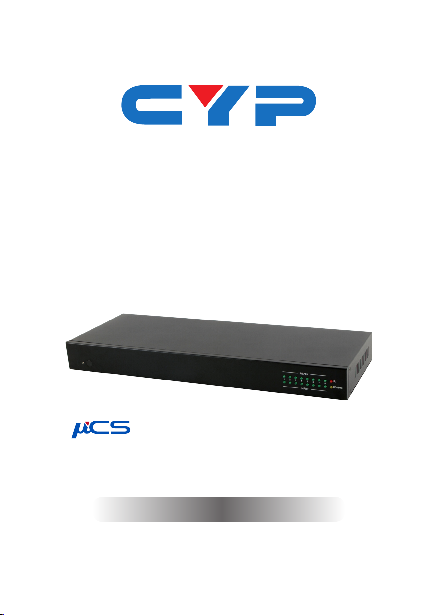
CDPS-CS4
Control System
Operation Manual
Operation Manual
Page 2

Page 3

DISCLAIMERS
The information in this manual has been carefully checked and
is believed to be accurate. Cypress Technology assumes no
responsibility for any infringements of patents or other rights of third
parties which may result from its use.
Cypress Technology assumes no responsibility for any inaccuracies
that may be contained in this document. Cypress also makes no
commitment to update or to keep current the information contained
in this document.
Cypress Technology reserves the right to make improvements to this
document and/or product at any time and without notice.
COPYRIGHT NOTICE
No part of this document may be reproduced, transmitted,
transcribed, stored in a retrieval system, or any of its part translated
into any language or computer le, in any form or by any means—
electronic, mechanical, magnetic, optical, chemical, manual, or
otherwise—without express written permission and consent from
Cypress Technology.
© Copyright 2011 by Cypress Technology.
All Rights Reserved.
Version 1.1 August 2011
TRADEMARK ACKNOWLEDGMENTS
All products or service names mentioned in this document may be
trademarks of the companies with which they are associated.
Page 4

SAFETY PRECAUTIONS
Please read all instructions before attempting to unpack, install or
operate this equipment and before connecting the power supply.
Please keep the following in mind as you unpack and install this
equipment:
• Always follow basic safety precautions to reduce the risk of re,
electrical shock and injury to persons.
• To prevent re or shock hazard, do not expose the unit to rain,
moisture or install this product near water.
• Never spill liquid of any kind on or into this product.
• Never push an object of any kind into this product through any
openings or empty slots in the unit, as you may damage parts
inside the unit.
• Do not attach the power supply cabling to building surfaces.
• Use only the supplied power supply unit (PSU). Do not use the PSU
if it is damaged.
• Do not allow anything to rest on the power cabling or allow any
weight to be placed upon it or any person walk on it.
• To protect the unit from overheating, do not block any vents or
openings in the unit housing that provide ventilation and allow for
sufcient space for air to circulate around the unit.
REVISION HISTORY
VERSION NO. DATE (DD/MM/YY) SUMMARY OF CHANGE
VR0 20/07/15 Preliminary release
Page 5

CONTENTS
1. Introduction ............................................ 1
2. Applications ........................................... 1
3. Package Contents ................................ 1
4. System Requirements ............................ 1
6. Operation Controls and Functions ....... 2
6.1 Front Panel ........................................2
6.2 Rear Panel .........................................3
6.3 Remote Control ................................4
6.4 IR Cable Pin Assignment..................4
6.5 RS-232 DTE Pin Assignment ..............5
6.6 RS-232 and Telnet Commands .......5
6.7 Software Application .......................7
6.8 Telnet Control ...................................8
6.9 WebGUI Control .............................10
6.9.1 Macro Settings ......................10
6.9.2 Extension Macro ....................13
6.9.3 Command Settings ............... 13
6.9.4 Network Settings ...................14
6.9.5 System Settings ......................15
7. Connection Diagram .......................... 16
8. Specications ...................................... 17
9. Acronyms ............................................. 18
Page 6

1. INTRODUCTION
By entering into a new era of smart world, the trend of controlling
everything with one nger is nowadays foreseen. Control System allows
your dream come true by providing not only direct but also indirect
control interfaces for all your devices. Direct control like IR, Relay and
DC controls allow users to maintain the traditional connection control
over the device whereas, indirect control like IR Learning, RS-232,
Telnet/WebGUI controls allow users with computing system or APP to
control over the devices. Overall, the management of all the controls
can be operated easily through IR remote control, RS-232, Telnet or
Ethernet protocols.
2. APPLICATIONS
• Smart Home Installation
• Even hall/Showroom control
3. PACKAGE CONTENTS
• 1×Control System
• 1× IR Learner Cable
• 4× IR Blaster Cables
• 4×3.5mm to 3.5mm IR Cables
• 4×Terminal Block Jacks
• 1×Remote Control
• 1×5 V/2.6 A Power Adaptor
• 1×Left and Right Rack Ears
• 1×Operation Manual
4. SYSTEM REQUIREMENTS
Input source equipment such as light, TV, power switch and ….etc.
and PC/Laptop.
1
Page 7

5
3
5. FEATURES
• Supports IR Learning function allows IR signal to be accepted by
computing system
• Supports eight inputs with voltage of 0~15V
• Supports 1 IR Learning, 8 IR outputs, 8 trigger inputs, 8 Relay outputs,
2 COM ports, and 4 Ethernet ports
• Supports Baud rate from 4800bps to 115200bps
• Supports 10/100 Ethernet network connection
6. OPERATION CONTROLS AND FUNCTIONS
6.1 Front Panel
RELAY
12345678
INPUT
1 6
2 4
1
POWER LED: This LED will illuminate when the device is switched on.
2
IR WINDOW: Receives IR signal frquency from the remote control
and can trigger macro even 1~8.
3
RELAY LED: These LEDs represent the relay output connections
status.
4
INPUT LED: These LEDs will illuminate when trigger the input
connection obtain active high DC of 5~15V which is also when
signals has been triggered.
5
IR LED: This LED will illuminate when the device is receiving or
sending IR signal, under IR Learning process the LED will illuminate
also.
6
COMMS LED: This LED will illuminate when the COM port is sending
or receiving data, under Macro run command executing the LED
will be ashing according to the numbers of command send.
IR
COMMS
2
Page 8

6.2 Rear Panel
1 62 3 4 5 5 7 8 9
IN
INFRARED OUT
1IRL 2345678
1
IRL: Connect with IR Receiver included in the package for IR signal
RELAY OUT
1 2345678 12345678
GND
COM 1 COM 2
RESET
LAN
1234
USB
learning. Send the IR signal that is to be learned by press on the
remote control in direct line-of-sight towards the Receiver and
record the IR data into digital format from WebGUI. For software
details please refers to section 6.9.3.
2
INFRARED OUT 1~8: Connect with IR Blaster for IR signal transmitting.
Place the IR Blaster in direct line-of-sight of the equipment to be
controlled.
3
IN 1~8: Connect with sensor device’s signal lines such as window
security alarm, door switch, and etc… for trigger signal sending
back to Control System.
4
RELAY OUT 1~8: Connect with control device’s power line cable
such as DC power supply to activate the control devices.
5
COM 1~2: Connect with RS-232 devices for command sending and
controllig the devices.
6
RESET: To reset IP back to factory default, press and hold the button
with pin for 10 seconds and both IR and comm LED will illuminate.
7
LAN 1~4: Connect with PC/Laptop or intra-net hub and also the
LAN connection of the control devices for Telnet/WebGUI control
over the devices.
8
USB: This slot is reserved for factory rmware update only.
9
DC 5V: Plug the 5V DC power supply into the unit and connect the
adaptor to an AC outlet.
DC 5V
3
Page 9
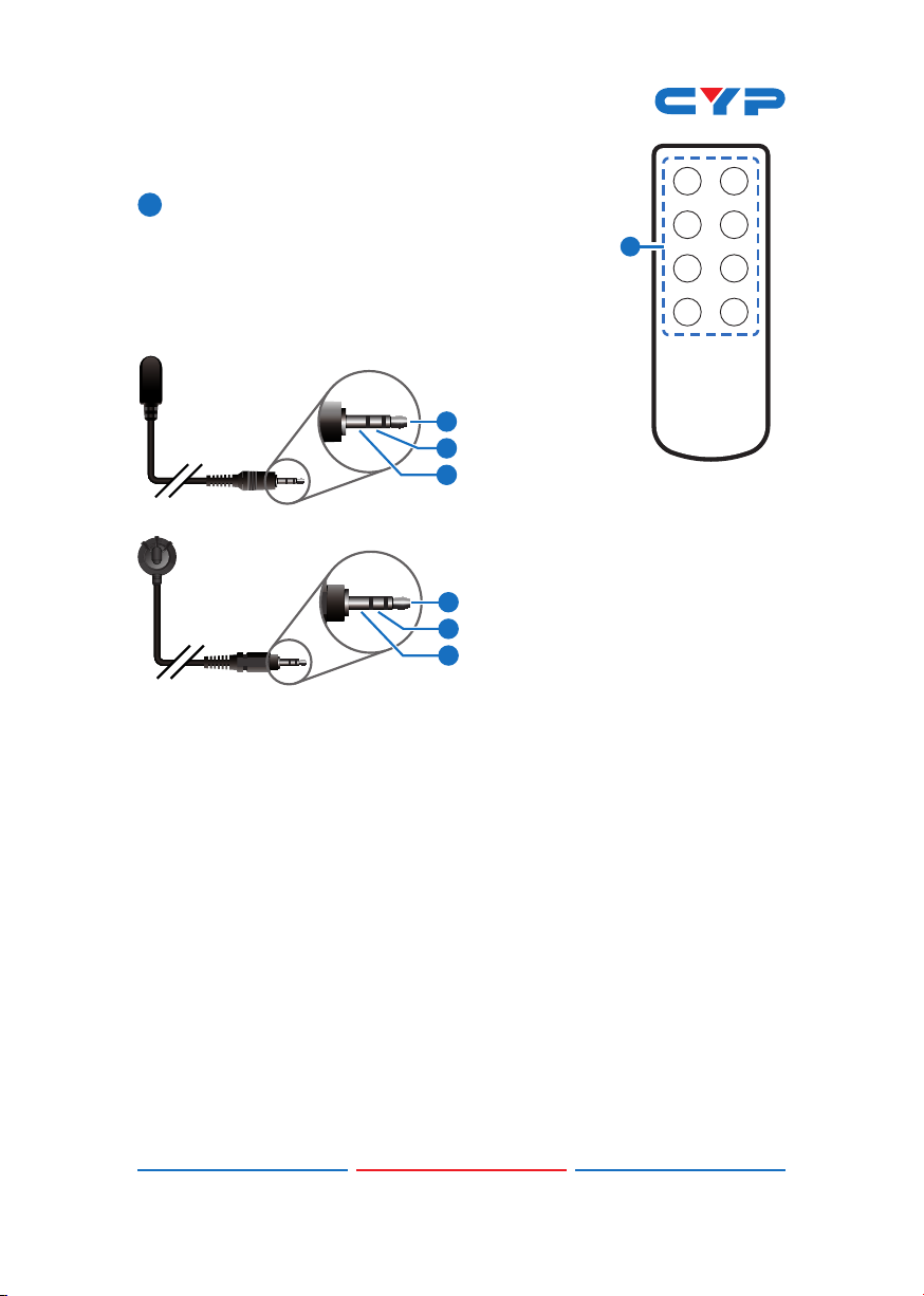
6.3 Remote Control
1
1~8: Press these buttons to trigger input signal
of input 1~8 for control system to activate the
corresponding command or setting.
12
34
1
56
6.4 IR Cable Pin Assignment
IR Blaster
IR Learner
1
Power
2
IR Signal
3
NC
1
IR Signal
2
Power
3
Grounding
78
CR-157
4
Page 10

6.5 RS-232 DTE Pin Assignment
DATA TERMINAL EQUIPMENT
Pin Assignment
1 NC
2 RxD
3 TxD
4 NC
5 GND
6 NC
7 NC
8 NC
9 NC
Baud Rate: 4800~115200bps
Data bit: 7~8 bits
Parity: None, Odd, Even
Flow Control: None
Stop Bit: 1~2 Bits
6.6 RS-232 and Telnet Commands
COMMAND DESCRIPTION PARAMETER
IPCONFIG Display the current IP
SIPADDR XXX.XXX.
XXX.XXX
SNETMASK XXX.
XXX. XXX.XXX
SGATEWAY XXX.
XXX. XXX.XXX
SIPMODE Set Ethernet IP mode N=STATIC/DHCP
VER Show unit rmware version NONE
REBOOT System reboot NONE
congure
Set Ethernet IP address XXX=0~255
Set Ethernet net mask XXX=0~255
Set Ethernet gateway XXX=0~255
NONE
5
Page 11

COMMAND DESCRIPTION PARAMETER
FADEFAULT All congure set to factory
ETH_FADEFAULT All Ethernet congure set
HELP (?) Show command list NONE
HELP N Show description of
RELAY N N1 Relay control N[PORT]=1~2
IREMIT N N1 N2 Send IR contenet N[PORT]=1~8,
COMSEND COM N N1Send command to COM
COMCONF N N1
N2 N3 N4
MACRO STOP N Stop Macro control N[PORT]=1~15
MACRO RUN N Run Macro control N[PORT]=1~15
default*
to factory
command
port
Driver RS-232 cong show
COM port settings
NONE
NONE
N=COMMAND NAME
N1[MODE]=CLOSE/OPEN
N1[MODE]=(0)CYP, N2=IR
EMIT DATA (STRING)
N[PORT]=1~2
N1=COMMAND DATA
(1~512 CHARS)
N[PORT]=1~2
N1[BAUDRATE]=4800, 9600,
19200, 38400, 57600, 115200
N2[DATA LEN]= 7, 8
N3[PARITY]=(0)NONE (1),
ODD (2)EVEN
N4[STOP BIT]=1,2
Note:
1. Any commands will not be executed unless followed by a carriage
return. Commands are case-sensitive.
2. Please ensure that all commands and settings have been saved
before performing this command with Asterisk (*) as the procedure
may restore all settings back to default.
6
Page 12
6.7 Software Application
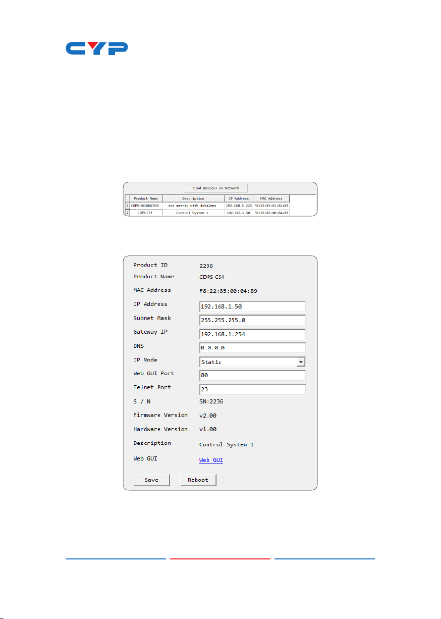
Please download the software from www.cypress.com.tw with le
name CDPS V2.000 and save it in a directory where you may use it
later.
Connect the Control System with an active network system and open
the CDPS V2.000 application from the directory in a PC/Laptop. Click
on Find Devices on Network and a list of the devices connected within
the network system will show up.
Double click on the product name and an InfoFrom will appear to
show the products’ detail.
Then user may use the IP Address to nd the control device through
Telnet, WebGUI or even RS-232/Hyper Terminal tools.
7
Page 13
6.8 Telnet Control
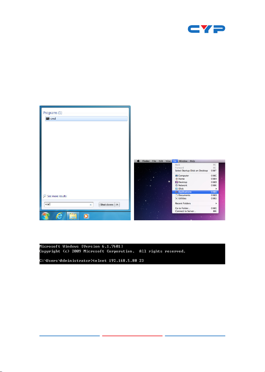
To access the Telnet control in Windows 7, click on the 'Start' menu
and type "cmd" in the Search eld then press enter.
Under Windows XP go to the 'Start' menu and click on "Run", type
"cmd" with then press enter.
Under Mac OS X, go to Go→Applications→Utilities→Terminal
See below for reference.
Once in the command line interface (CLI) type "telnet", then the IP
address of the unit and "23", then hit enter.
8
Page 14

This will bring us into the unit which we wish to control. Type "help" to
list the available commands.
Note: Commands will not be executed unless followed by a carriage
return. Commands are case-sensitive. If the IP is changed then the IP
Address required for Telnet access will also change accordingly.
9
Page 15

6.9 WebGUI Control
On a PC/Laptop that is connected to an active network system,
open a web browser and type device’s IP address (default setting IP:
192.168.1.50 ) on the web address entry bar.
A security page will appear to ask for User and Password, please key
in “admin” for both and click Submit to enter. The browser will display
device’s Macro Setting, Extension Macro, Command, Network &
System Settings control pages for users to control.
6.9.1 Macro Settings
Click on 'Macro Settings' to execute or rename macro. There are
5 Macros inserted as default setting for testing the control system's
functionality. Click on Macro 1~5 to demonstrate the functions:
• Macro 1: Close relay from 1~8 sequentially every 100ms
• Macro 2: Open relay from 1~8 sequentially every 100ms
• Macro 3: Toggles relay from 1~8 sequentially every 100ms
• Macro 4: Send IR signal from 1~8 sequentially every 100ms with LED
illuminant on front panel.
• Macro 5: Send out command "Hello World" from COM port 1~2
sequentially every 100ms.
10
Page 16

Click on the mark to edit the command settings. Up/down
arrows are to move the command up or down and button is to
delete the command.
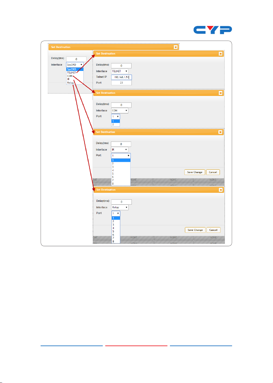
Click on Insert button/Add to insert commands. Command can be
set to control the Control System/SysCMD, other devices connected
within the same Telnet system/Internet area, RS-232 COM ports, IR and
Relay devices connected through the Relay outputs of Control System
with delay time. It is suggested the delay time is >100ms once the
setting is conmed, double click on Save Change.
Command set to control the devices within the same telent system
or internet area require to set its IP and Port number and it is strongly
recommand to set the delay time >500ms in order to secure a
successful command sending. Command set to control the Relay
devices require to set the Port number. Click on Save Change to
conrm the setting.
11
Page 17
12
Page 18
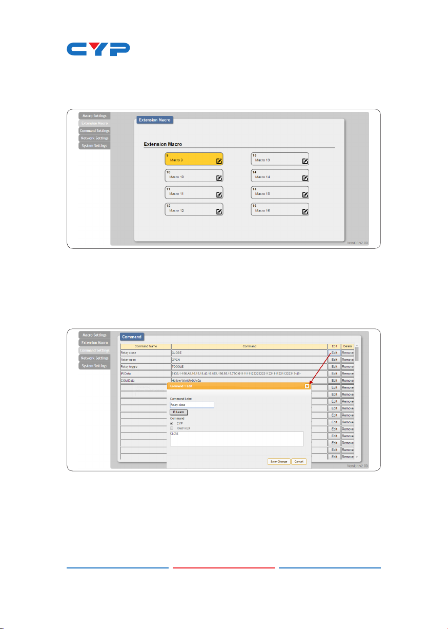
6.9.2 Extension Macro
Click on 'Extension Macro' to execute/edit more Macro action up to 8
more.
6.9.3 Command Settings
Click on 'Command Settings' to edit or delete commands up to 128
sets. Insert the command directly in the bottom colum of Command
Edit and name the command on the top colum then click on Save
Changes to store the command.
For IR command Learning, press IR Learn rst then press the remote
control in direct line-of-sight to the IR Reciever connected from the IRL
port within 5 seconds. A comand string will show in the bottom colum.
Click on Save Changes to store the command.
For IR command saving, insert the command on the bottom colum
and click on CYP/RAW HEX which indicate the IR command type
and click on Save changes to store the command. Under uncertainty
13
Page 19
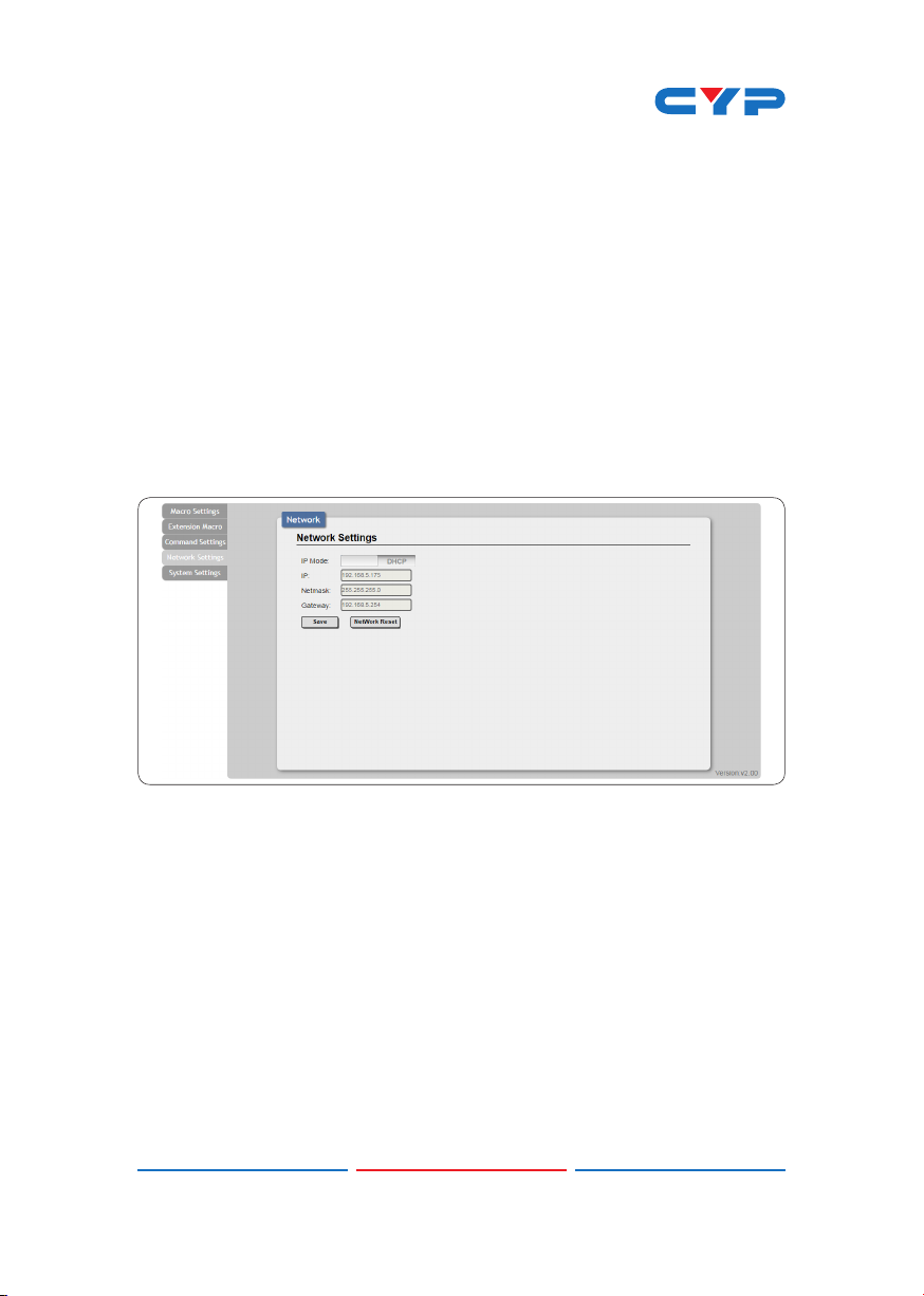
of the IR command type click on RAW HEX to ensure a successful
command saving.
Command under 128 characters including space can be build up
to 128 commands, command over 128 characters and under 512
characters including space can be build up to 32 command in
addition with 96 commands of 128 characters under. Click on Save
Change to save the command inserted.
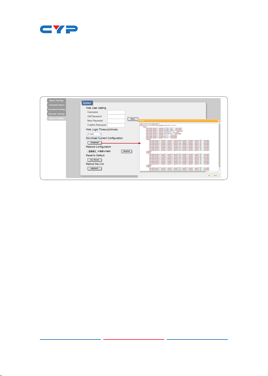
6.9.4 Network Settings
Click on 'Network Settings' to set the device’s IP conguration. Once
the changes are saved the system will reset the IP address on device
automatically and user will need to re-enter the IP address to continue
the WebGUI control.
14
Page 20
6.9.5 System Settings
Click on 'System Settings' to reset the WebGUI login password and
save or download the Macro settings. Reset to Default allows IP and
login ID & password to be reset back to factory default.
Note: Please ensure that all commands and settings have been saved
before performing Reset as this procedure may restore all settings
back to factory default.
15
Page 21
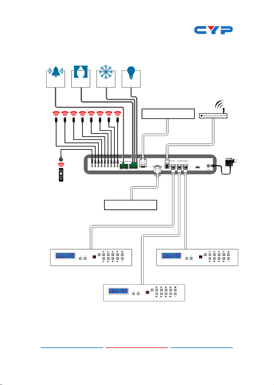
7. CONNECTION DIAGRAM
Integrated 3rd Party Control
IR Blaster
IR Learner
Alarm
Sensor
Blind
Control
POWERLOCK
DC
Control
INFRARED OUT
1IRL2345678
IN
1 2345678 12345678
GND
RS-232 Control System
1B2C3D4
MENU OUTA
5F6G7H8
E
IN
Lighting
Control
RELAY OUT
RS-232
COM 1COM 2
RESET
LAN
1234
POWERLOCK
Internet
Connected
RouterRS-232 Control System
LAN
USB
LAN
Connections
MENU OUTA
DC 5V
1B2C3D4
5F6G7H8
E
Power
Supply
IN
1B2C3D4
POWER LOCK
MENU OUTA
5F6G7H8
E
IP Control Enabled
Devices
IN
16
Page 22

8. SPECIFICATIONS
Input Ports 8×Triggers (Ternimal Block), 4×LAN (RJ-45),
1×IR Learner
Output Ports 8×Replays (Ternimal Block), 8×IR Blasters,
2×COM (9-pin D-sub)
IR Out Frequency 30~50 kHz
IR Learner Frequency 30~55 kHz
Baud Rate 4800~115200 bps
Power Supply 5 V/2.6 A DC (US/EU standards, CE/FCC/UL
certied)
ESD Protection Human body model:
±8 kV (air-gap discharge)
±4 kV (contact discharge)
Dimensions 432 mm (W)×174 mm (D)×44 mm (H)/
Jack Excluded
432 mm (W)×181 mm (D)×49 mm (H)/
Jack Included
Weight 2186 g
Chassis Material Metal
Color Black
Operating Temperature 0˚C~40˚C/32˚F~104˚F
Storage Temperature −20˚C~60˚C/−4˚F~140˚F
Relative Humidity 20~90% RH (non-condensing)
Power Consumption 7.7 W
17
Page 23

9. ACRONYMS
ACRONYM COMPLETE TERM
CLI Command Line Interface
GUI Graphical User Interface
IP Internet Protocol
IR
IRL Infrared Learning
LAN Local Area Network
Infrared
18
Page 24

CYPRESS TECHNOLOGY CO., LTD
Home page: http://www.cypress.com.tw
 Loading...