

Page 1
CD62__15A
Powerex, Inc., Hillis Street, Youngwood, Pennsy l vania 15697 (724) 925-7272
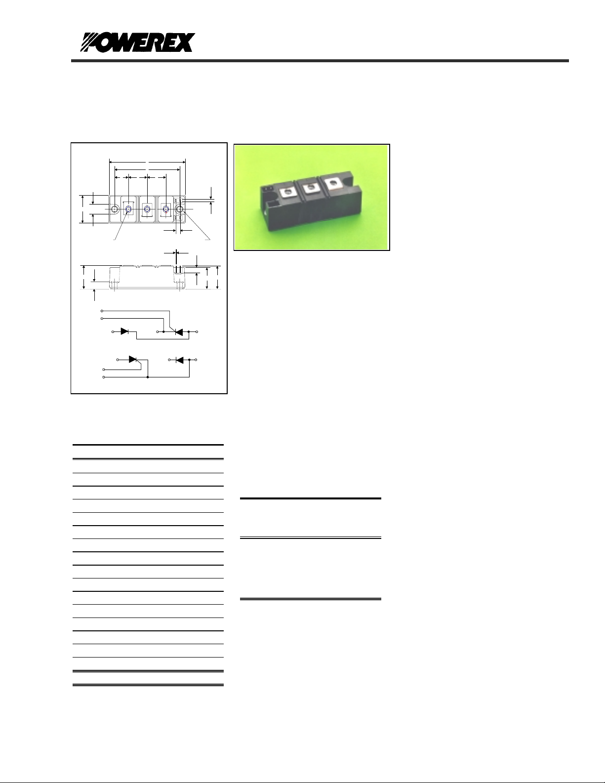
Dual SCR/Diode Isolated Module
B
C
G
"J" (3)
H
4
5
OUTLINE DRAWING
E
12 3
-
3
A
D
F F
7
6
S
4
5
M
F
"K" (2)
R
N
P
CD62
+
2
~
1
CD62__15A, CD67__15A
Q
Dual SCR/Diode Isolated
POW-R-BLOK
TM
Module
150 Amperes / Up to 1600 Volts
CD67
-
3
6
7
CONNECTION DIAGRAMS
+
2
~
1
CD62__15A, CD67__15A
Outline Dimensions
Dimension Inches Millimeters
A 3.70 94
B 1.38 35
C 1.18 30
D 3.15 80
E 0.67 17
F 0.91 23
G 0.57 14.5
H 0.35 9
J M6 M6
K 0.26 6.5
M .020 5
N 0.28 7
P 1.10 28
Q 1.14 29
R 0.03 0.8
S 0.11 2.8
Note: Dimensions are for reference only.
Ordering Information
Select the complete nine digit module
part number from the table below.
Example: CD621615A is a 1600Volt,
150 Ampere SCR/Diode Isolated
POW-R-BLOK
TM
Module
Type
CD62
CD67
Voltage
Volts
(x100)
08
12
14
16
:
Current
Amperes
(x 10)
15
POW-R-BLOK
150 Amperes / Up to 1600 Volts
CD67__15A
TM
Description:
Powerex SCR/Diode Modules are
designed for use in applications
requiring phase control and isolated
packaging. The modules are isolated
for easy mounting with other
components on a common heatsink.
POW-R-BLOK
recognized by the Underwriters
Laboratories.
Features:
T Electrically Isolated Heatsinking
T DBC Alumina (Al
T Glass Passivated Chips
T Metal Baseplate
T Low Thermal Impedance
for Improved Current Capability
T Quick Connect Gate Terminal
with Provision for Keyed Mating
Plug
T UL Recognized (E78240)
Benefits:
T No Additional Insulation
Components Required
T Easy Installation
T No Clamping Components
Required
T Reduce Engineering Time
Applications:
T Bridge Circuits
T AC & DC Motor Drives
T Battery Supplies
T Power Supplies
T Large IGBT Circuit Front Ends
T Lighting Control
T Heat & Temperature Control
T Welders
TM
has been tested and
) Insulator
2O3
Revision Date: 12/04/2002
Page 2

CD62__15A
Powerex, Inc., Hillis Street, Youngwood, Pennsy l vania 15697 (724) 925-7272
Dual SCR/Diode Isolated Module
Absolute Maximum Ratings
Characteristics Conditions Symbol Units
Repetitive Peak Forward and Reverse Blocking
Voltage
Non-Repetitive Peak Reverse Blocking Voltage
(t < 5 msec)
RMS Forward Current 180° Conduction, TC=85°C
180° Conduction, T
Average Forward Current 180° Conduction, TC=85°C
180° Conduction, T
Peak One Cycle Surge Current, Non-Repetitive
60 Hz, 100% V
60 Hz, No V
50 Hz, 100% V
50 Hz, No V
Peak Three Cycle Surge Current, Non-Repetitive
60 Hz, 100% V
50 Hz, 100% V
Peak Ten Cycle Surge Current, Non-Repetitive
60 Hz, 100% V
50 Hz, 100% V
I2t for Fusing for One Cycle
8.3 ms, 100% V
8.3 ms, No V
10 ms, 100% V
10 ms, No V
Maximum Rate-of-Rise of On-State Current,
Non Repetitive
Peak Gate Power Dissipation
Average Gate Power Dissipation
Peak Forward Gate Current
Peak Reverse Gate Voltage
=1.0 V
V
D
I
=0.5 A, Tr < 0.25µs, tp > 6µs
G
T
< 5 ms, Tj = 125°C
p
F = 50 Hz, T
T
< 5 ms, Tj = 125°C
p
T
< 5 ms, Tj = 125°C
p
Operating Temperature TJ -40 to +125 °C
Storage Temperature T
Max. Mounting Torque, M6 Mounting Screw on
Terminals
Max. Mounting Torque, Module to Heatsink 35 - 50
Module Weight, Typical 200 G
7.1 Oz.
V Isolation @ 25C V
V
V
=85°C (AC Switch)
C
=90°C
C
reapplied, Tj=125°C
RRM
reapplied, Tj=125°C
RRM
reapplied, Tj=125°C
RRM
reapplied, Tj=125°C
RRM
reapplied, Tj=125°C
RRM
reapplied, Tj=125°C
RRM
reapplied, Tj=125°C
RRM
reapplied, Tj=125°C
RRM
reapplied, Tj=125°C
RRM
reapplied, Tj=125°C
RRM
reapplied, Tj=125°C
RRM
reapplied, Tj=125°C
RRM
T
=125°C,
j
DRM (Rated), ITM
=400A ,
= 125°C
j
35 - 50
POW-R-BLOK
150 Amperes / Up to 1600 Volts
CD67__15A
TM
& V
DRM
I
T(RMS)
I
T(RMS)
I
I
di/dt 300 A/µs
P
P
I
V
up to 1600 V
RRM
V
RSM
T(AV)
T(AV)
I
TSM
I
TSM
I
TSM
I
TSM
I
TSM
I
TSM
I
TSM
I
TSM
2
t
I
2
t
I
2
I
t
2
t
I
12 W
GM
3 W
G(AV)
3 A
GFM
10 V
GRM
-40 to +150 °C
stg
+ 100 V
RRM
250
355
160
150
4300
5100
4100
4870
3250
3150
2650
2550
76,700
108,000
84,000
119,000
A
A
A
A
A
A
A
A
A
A
A
A
A2 sec
2
sec
A
2
sec
A
2
sec
A
in.-Lb.
4 - 6
Nm
in.-Lb.
4 - 6
3500 V
rms
Nm
Revision Date: 12/04/2002
Page 3

CD62__15A
Powerex, Inc., Hillis Street, Youngwood, Pennsy l vania 15697 (724) 925-7272
Dual SCR/Diode Isolated Module
Electrical Characteristics, TJ=25°C unless otherwise specified
Characteristics Symbol Test Conditions Min. Max.
Repetitive Peak Forward Leakage Current I
Repetitive Peak Reverse Leakage Current I
Peak On-State Voltage VTM / VFM I
Threshold Voltage, Low-level
Slope Resistance, Low-level
Threshold Voltage, High-level
Slope Resistance, High-level
VTM Coefficients, Full Range
Minimum dV/dt dV/dt Exponential to 2/3 V
Turn-On Time (Typical) ton I
Turn-Off Time (Typical) t
Gate Trigger Current IGT
Gate Trigger Voltage VGT
Non-Triggering Gate Voltage V
Non-Triggering Gate Current I
Up to 1600V, TJ=125°C 50 mA
DRM
Up to 1600V, TJ=125°C 50 mA
RRM
/ I
TM
V
V
(TO)1
r
T1
(TO)2
r
T2
T
= 125°C, I = 16.7% x πI
J
= 125°C, I = πI
T
J
TJ = 125°C, I = 15% x I
off
V
= A+ B Ln I +C I + D Sqrt I
TM
T
=125°C, Gate Open
j
= 300A, VD = 2/3 V
TM
T
= 125°C, IT= 300A, Rgk = 100Ω
J
= 50V, -dI/dt=15 A/µs
V
r
Re-Applied dV/dt = 20V/µs,
Linear to 2/3 V
T
= -40°C, VD=6V, Ra=1Ω, Resistive Load
j
= 25°C, VD=6V, Ra=1Ω Resistive Load
T
j
=125°C, VD=6V, Ra=1Ω, Resistive Load
T
j
T
= -40°C, VD=6V, Ra=1Ω, Resistive Load
j
= 25°C, VD=6V, Ra=1Ω, Resistive Load
T
j
=125°C, VD=6V, Ra=1Ω, Resistive Load
T
j
T
GDM
T
GDM
=125°C, VD=V
j
=125°C, VD=V
j
POW-R-BLOK
150 Amperes / Up to 1600 Volts
=500A 1.54 V
FM
T(AV)
T(AV)
T(AV)
dIg/dt =1A/µs 3 (Typical) µs
DRM
DRM
DRM
DRM
CD67__15A
TM
Units
to πI
to I
to I
DRM
0.30 Volts
10 mA
0.80
T(AV)
1.67 V mΩ
0.98
TSM
1.38 V mΩ
TSM
A =
B =
C =
D =
1000 V/µs
0.5926
-1.10E-03
1.03E-03
0.0241
50 - 200 (Typical) µs
270
150
80
4.0
2.5
1.7
mA
mA
mA
Volts
Volts
Volts
Thermal Characteristics
Characteristics Symbol
Thermal Resistance, Junction to Case
DC Operation
Thermal Impedance Coefficients
(Per Junction)
R
Z
ΘJ-C
Θ
J-C
Per Module, both conducting
Per Junction, both conducting
Z
Θ
J-C
+ K
+ K
+ K
Thermal Resistance, Case to Sink Lubricated
R
ΘC-S
= K1 (1-exp(-t/
(1-exp(-t/
2
(1-exp(-t/
3
(1-exp(-t/
4
))
τ
1
))
τ
2
))
τ
3
))
τ
4
Per Module 0.05 °C/W
=5.45334E-3
K
1
K2 =3.8509E+1
K3 = -3.5154E+1
K4 = -3.20
Max. Units
=4.511E-5
τ
1
=1.3558E-1
τ2
=1.3311E-1
3
τ
=1.5936E-1
4
τ
0.08
0.16
°C/W
°C/W
Revision Date: 12/04/2002
Page 4

CD62__15A
Powerex, Inc., Hillis Street, Youngwood, Pennsy l vania 15697 (724) 925-7272
Dual SCR/Diode Isolated Module
POW-R-BLOK
150 Amperes / Up to 1600 Volts
CD67__15A
TM
Maximum On-State Forward Voltage Drop
5
4
3
2
1
On-State Voltage - Vtm / Vfm - Volts
0
10 100 1000 10000
240
220
200
180
160
140
120
100
80
60
40
Max. Power Dissipation Per Junction - Watts_
20
0
0 20406080100120140160180
Instantaneous On-State Current - Itm / Ifm - Amperes
Maximum On-State Power Dissipation
15°
Average On-State Current - It(av) / If(av) - Amperes
( Tj = 125 °C )
(Sinusoidal Waveform)
60°
30°
0
CONDUCTION ANGLE
120°
90°
180
180°
360
Maximum Transient Thermal Impedance
0.180
0.160
0.140
0.120
0.100
0.080
0.060
Thermal Impedance - Rjc - °C/W
0.040
0.020
0.000
0.01 0.1 1 10
(Junction to Case)
Time - t - Seconds
Maximum Allowable Case Temperature
(Sinusoidal Waveform)
125
120
115
180
110
105
100
95
Max. Case Temperature - Tcase -°C_
90
85
0 20406080100120140160180
15°
30°
0
CONDUCTION ANGLE
60°
90°
120°
360
180°
Average On-State Current - It(av) / If(av) - Amperes
Maximum On-State Power Dissipation
(Rectangular Waveform)
320
300
280
260
240
220
200
180
160
140
120
100
80
60
40
Max. Power Dissipatio n Per Junction - W atts_
20
0
0 20 40 60 80 100 120 140 160 180 200 220 240 260
15°
30°
90°
60°
180°
120°
0
CONDUCTION ANGLE
270°
180
Average On-State Current - It(av) / If(av) - Amperes
360°
360
Maximum Allowable Case Temperature
(Rectangular Waveform)
125
120
115
110
105
100
95
90
85
Max. Case Temperature - Tcase -°C_
80
75
0 20 40 60 80 100 120 140 160 180 200 220 240 260
15°
30°
60°
0
CONDUCTION ANGLE
90°
120°
180
180°
270°
Average On-State Current - It(av) / If(av) - Amperes
Revision Date: 12/04/2002
360
360°
Page 5

CD62__15A
Powerex, Inc., Hillis Street, Youngwood, Pennsy l vania 15697 (724) 925-7272
Dual SCR/Diode Isolated Module
POW-R-BLOK
150 Amperes / Up to 1600 Volts
CD67__15A
TM
Powerex CD62 & CD67--15 Pow-R-Blok 6-Pulse Bridge
Total Power Dissipation (W)
1500
1400
1300
1200
1100
1000
900
800
700
600
500
400
300
200
100
0.025
0.03
0.04
0.05
0.06
0.08
0.10
0.12
0.15
0.20
0.30
0.40
0.60
0.02
Rth S-A (C/W)
0
10 30 50 70 90 110 130
Ambient Temperature (C)
Total Power Dissipation vs Maximum Rated Output Current
1500
1400
1300
1200
1100
1000
900
800
700
600
500
400
300
200
100
0
0 50 100 150 200 250 300 350 400 450
Maximum Bridge Output Current (A)
Six-Pulse Bridge Circuit Total Power Dissipation & Maximum Rated Output Current With Sink to Ambient
Resistance of Heatsink as a Parameter.
1500
1400
1300
1200
1100
1000
900
800
700
600
500
400
300
200
100
0
Total Power Dissipation (W)
Revision Date: 12/04/2002
 Loading...