

Page 1
CD61__16A, CS61__16A
CN61__16A, CC61__16A
Powerex, Inc., Hillis Street, Youngwood, Pennsy l vania 15697 (724) 925-7272
Dual & Single Diode Isolated Module
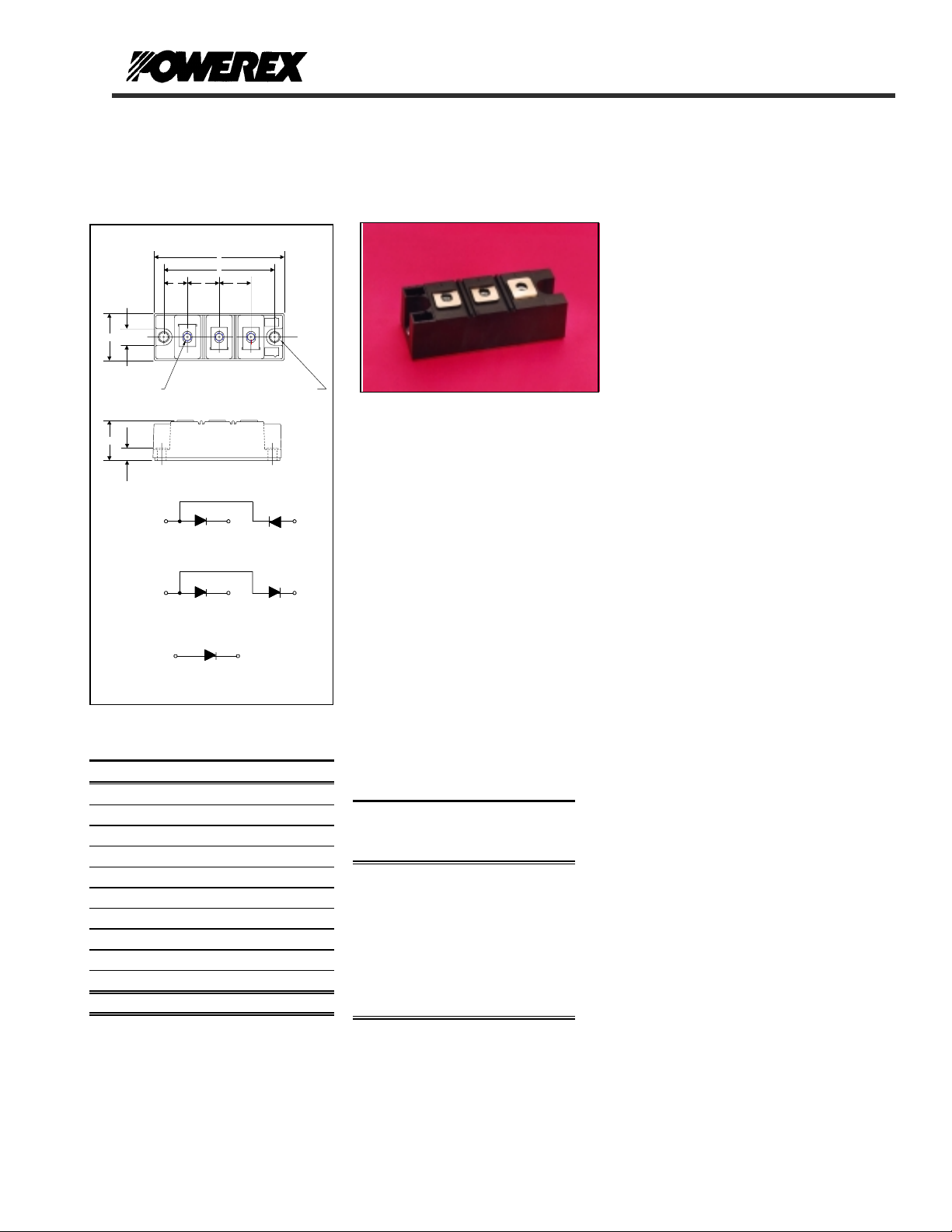
OUTLINE DRAWING
A
D
F F
E
POW-R-BLOK
160 Amperes / Up to 1600 Volts
Description:
Powerex Dual Diode & Single Diode
Modules are designed for use in
applications requiring rectification and
isolated packaging. The modules are
isolated for easy mounting with other
G
B
12
3
components on a common heatsink.
POW-R-BLOK
recognized by the Underwriters
"J" (3 )
"K" (2)
Laboratories.
F
Features:
T Electrically Isolated Heatsinking
T DBC Alumina Insulator
T Glass Passivated Chips
T Metal Baseplate
T Low Thermal Impedance
for Improved Current Capability
T UL Recognized (E78240)
Benefits:
T No Additional Insulation
Components Required
T Easy Installation
T No Clamping Components
Required
T Reduce Engineering Time
Applications:
T Power Supplies
T Bridge Circuits
T AC & DC Motor Drives
T Battery Supplies
T Large IGBT Circuit Front Ends
T Welders
C
H
CD61
CN61
CS61
~
1
-
1
-
1
CONNECTION DIAGRAMS
+
2
+
2
+
-
3
+
3
2
Outline Dimensions
Dimension Inches Millimeters
A 3.70 94
B 1.38 35
C 1.18 30
D 3.15 80
E 0.67 17
F 0.91 23
G 0.57 14.5
H 0.35 9
J M6 M6
K 0.26 6.5
Note: Dimensions are for reference only.
CD61__16A, CS61__16A
CN61__16A, CC61__16A
Dual & Single Diode Isolated
POW-R-BLOK
TM
Module
160 Amperes / Up to 1600 Volts
Ordering Information
Select the complete nine digit module
part number from the table below.
Example: CD611616A is a 1600 Volt,
160 Ampere Dual Diode Isolated
POW-R-BLOK
TM
Module
:
Type
CD61
CN61
CC61
CS61
Voltage
Volts
(x100)
08
12
14
16
Current
Amperes
(x10)
16
TM
TM
has been tested and
Revision Date: 12/04/2002
Page 2

CD61__16A, CS61__16A
CN61__16A, CC61__16A
Powerex, Inc., Hillis Street, Youngwood, Pennsy l vania 15697 (724) 925-7272
Dual & Single Diode Isolated Module
POW-R-BLOK
160 Amperes / Up to 1600 Volts
Absolute Maximum Ratings
Characteristics Conditions Symbol Units
Repetitive Peak Reverse Blocking Voltage V
Non-Repetitive Peak Reverse Blocking Voltage
(t < 5 msec)
RMS Forward Current 180° Conduction, TC=100°C I
Average Forward Current 180° Conduction, TC=100°C I
Peak One Cycle Surge Current, Non-Repetitive
60 Hz, 100% V
60 Hz, 100% No V
50 Hz, 100% V
50 Hz, 100% No V
Peak Three Cycle Surge Current, Non-Repetitive
60 Hz, 100% V
50 Hz, 100% V
Peak Ten Cycle Surge Current, Non-Repetitive
60 Hz, 100% V
50 Hz, 100% V
I2t for Fusing for One Cycle
8.3ms, 100% V
8.3ms, 100% No V
10ms, 100% V
10ms, 100% No V
Operating Temperature TJ -40 to +150 °C
Storage Temperature T
Max. Mounting Torque, M6 Mounting Screw 35 - 50
Max. Mounting Torque, M8 Terminal Screw 35 - 50
Module Weight, Typical 200 g
7.1 lb.
V Isolation @ 25C, V
for 1 sec V
rms
V
F(RMS)
reapplied, TJ=150C
RRM
reapplied, TJ=150C
RRM
reapplied, TJ=150C
RRM
reapplied, TJ=150C
RRM
reapplied, TJ=150C
RRM
reapplied, TJ=150C
RRM
reapplied, TJ=150C
RRM
reapplied, TJ=150C
RRM
reapplied, TJ=150C
RRM
reapplied, TJ=150C
RRM
reapplied, TJ=150C
RRM
reapplied, TJ=150C
RRM
I
I
I
I
I
I
I
I
TM
up to 1600 V
RRM
V
RSM
+ 100 V
RRM
260 A
165 A
F(AV)
A
A
A
A
A
A
A
A
A
A
A
A
2
sec
2
sec
2
sec
2
sec
FSM
FSM
FSM
FSM
FSM
FSM
FSM
FSM
2
I
t
2
I
t
2
I
t
2
I
t
-40 to +150 °C
stg
3,500
4,200
3,350
4,000
2,600
2,480
1,750
1,820
52,000
73,000
56,000
80,000
in.-Lb.
4 - 6
Nm
in.-Lb.
4 - 6
3500 V
rms
Nm
Revision Date: 12/04/2002
Page 3

CD61__16A, CS61__16A
CN61__16A, CC61__16A
Powerex, Inc., Hillis Street, Youngwood, Pennsy l vania 15697 (724) 925-7272
Dual & Single Diode Isolated Module
POW-R-BLOK
160 Amperes / Up to 1600 Volts
Electrical Characteristics, TJ=25°C unless otherwise specified
Characteristics Symbol Test Conditions Min. Max. Units
Repetitive Peak Reverse Leakage Current I
Peak On-State Voltage VFM I
Threshold Voltage, Low-level
Slope Resistance, Low-level
Threshold Voltage, High-level
Slope Resistance, High-level
VTM Coefficients, Full Range
Up to 1600V, TJ=150°C 20 mA
RRM
=520A, 180 Deg Conduction 1.43 V
FM
V
V
(TO)1
r
T1
(TO)2
r
T2
= 150°C, I = 16.7%πI
T
J
T
= 150°C, I = πI
J
TJ = 150°C, I = 15%I
V
= A+ B Ln I +C I + D Sqrt I
FM
F(AV)
F(AV)
F(AV)
to πI
F(AV)
to I
0.88
FSM
to I
FSM
TM
0.73
1.5
1.26
A =
B =
C =
D =
0.563
0.0392
1.31 E-3
-8.25 E-5
V
mΩ
V
mΩ
Thermal Characteristics
Characteristics Symbol
Thermal Resistance, Junction to Case
Thermal Impedance Coefficients
R
Z
ΘJ-C
Θ
J-C
Per Module, both conducting
Per Junction both conducting
Z
Θ
J-C
+ K
+ K
+ K
Thermal Resistance, Case to Sink Lubricated
R
ΘC-S
= K1 (1-exp(-t/
(1-exp(-t/
2
(1-exp(-t/
3
(1-exp(-t/
4
))
τ
1
))
τ
2
))
τ
3
))
τ
4
Per Module 0.05 °C/W
= 1.84E-2
K
1
K2 = 4.68E-2
K3 = 8.25E-2
K4 = 5.23E-2
τ
1
τ2
τ3
τ4
Max.
0.1
0.2
= 2.53E-6
= 6.44E-2
= 3.11E-1
= 1.32
Units
°C/W
°C/W
Revision Date: 12/04/2002
Page 4

CD61__16A, CS61__16A
s
CN61__16A, CC61__16A
Powerex, Inc., Hillis Street, Youngwood, Pennsy l vania 15697 (724) 925-7272
Dual & Single Diode Isolated Module
POW-R-BLOK
160 Amperes / Up to 1600 Volts
TM
Maximum On-State Forward Voltage Drop
( Tj = 150 °C )
5
4
3
2
On-State Voltage - Vfm - Volt
1
0
10 100 1000 10000
Instantaneous On-State Current - Ifm - Amperes
Maximum On-State Power Dissipation
250
200
150
100
Max. Power Dissipation Per Diode - Watts_
50
0
0 20 40 60 80 100 120 140 160 180
(Sinusoidal Waveform)
90°
60°
30°
180
0
CONDUCTION ANGLE
Average On-State Current - If(av) - Amperes
120°
360
180°
Maximum Transient Thermal Impedance
(Junction to Case, Per Diode)
0.22
0.20
0.18
0.16
0.14
0.12
0.10
0.08
0.06
Thermal Impedance - Rjc - °C/W
0.04
0.02
0.00
0.01 0.1 1 10
Time - t - Seconds
Maximum Allow able Case T emperature
150
140
130
120
Max. Case Temperature - Tcase -°C_
110
100
0 20 40 60 80 100 120 140 160 180
(Sinusoidal Waveform)
180
0
CONDUCTION ANGLE
30°
60°
90°
120°
Average O n-S tate Cu rrent - If(av) - Am peres
360
180°
Maxim u m On-Stat e P o w e r D is sip a tio n
300
250
200
150
100
Max. Power Dissipation Per Diode - Watts_
50
0
0 20 40 60 80 100 120 140 160 180 200 220 240 260 280
(Rectangular Wavef orm )
180°
120°
90°
60°
30°
180
0
CONDUCTION ANGLE
Average On-Sta te Curr ent - If(av) - Amperes
360 °
360
150
140
130
120
110
Max. Case Temperature - Tcase -°C_
100
90
0 20 40 60 80 100 120 140 160 180 200 22 0 240 260 280
Maximum Allowa b le Case Temperature
(Rectangular Waveform)
0
CONDUCTION ANGLE
30°
60°
90°
120°
180°
Average On-State Current - If(av) - Amperes
180
360
360°
Revision Date: 12/04/2002
Page 5

CD61__16A, CS61__16A
CN61__16A, CC61__16A
Powerex, Inc., Hillis Street, Youngwood, Pennsy l vania 15697 (724) 925-7272
Dual & Single Diode Isolated Module
POW-R-BLOK
160 Amperes / Up to 1600 Volts
TM
Powerex CD61--16 Pow-R-Blok 6-Pulse Bridge
Total Power Dissipation (W)
1500
1400
1300
1200
1100
1000
900
800
700
600
500
400
300
200
100
0
0.03 0.025 0.02
0.04
0.05
0.06
0.08
0.10
0.12
0.15
0.20
0.30
0.40
0.60
10 30 50 70 90 110 130 150
Ambient Temperature (C)
Rth S-A (C/W)
Six-Pulse Bridge Circuit Total Power Dissipation & Maximum Rated Output Current With Sink to Ambient
Resistance of Heatsink as a Parameter.
Total Power Dissipation vs Maximum Rated Output Current
1500
1400
1300
1200
1100
1000
900
800
700
600
500
400
300
200
100
0
0 50 100 150 200 250 300 350 400 450 500
Maximum Bridge Output Current (A)
1500
1400
1300
1200
1100
1000
900
800
700
600
500
400
300
200
100
0
Total Power Dissipation (W)
Revision Date: 12/04/2002
 Loading...