

Page 1
CD42__90A
Powerex, Inc., Hillis Street, Youngwood, Pennsylvania 15697 (724) 925-7272
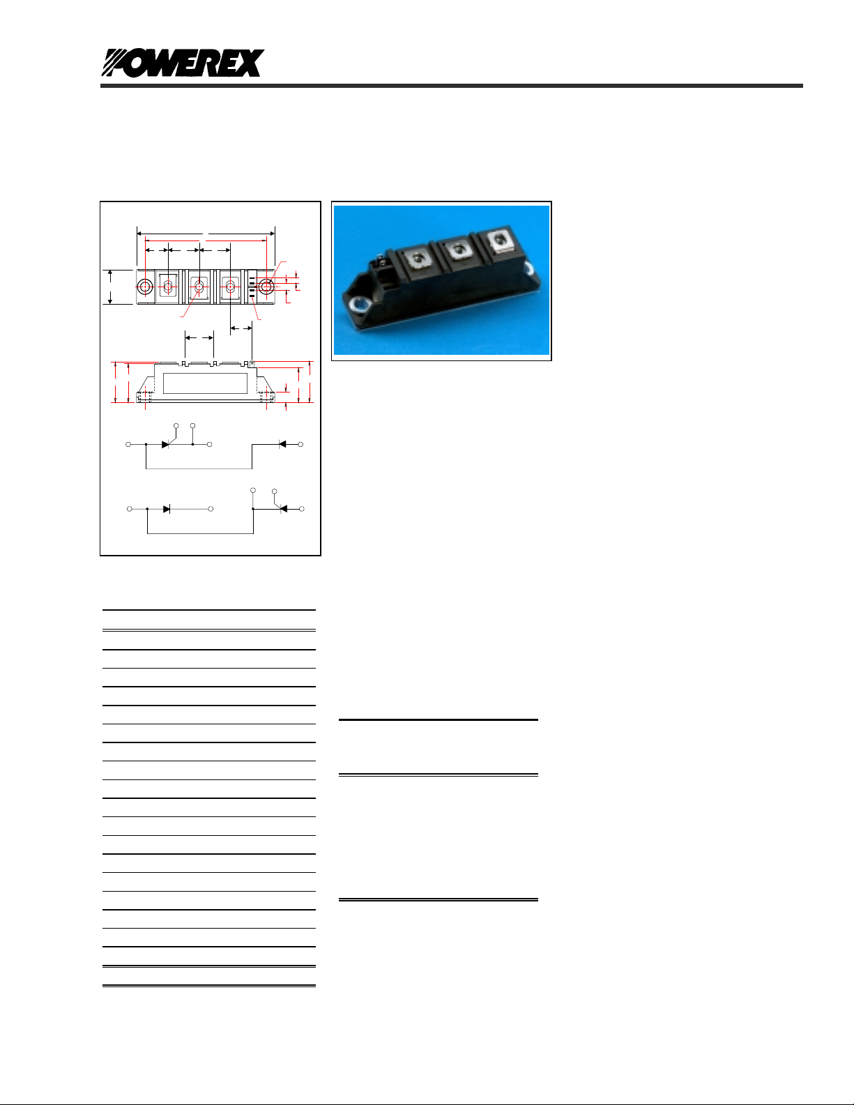
Dual SCR/Diode Isolated Module
POW-R-BLOK
90 Amperes / Up to 1600 Volts
CD47__90A
TM
OUTLINE DRAWING
A
C
B
M
D
~
~
1
"U" THREAD
4
1
1
CONNECTION DIAGRAM
G HF
2
3
R
LABEL
5
L
CD42
2
+
CD47
2
+
76
45
"S" FASTON TAB
7
6
T
J
K
P
N
3
-
3
-
CD42, CD47 Outline Dimensions
Dimension Inches Millimeters
A 3.62 92
B 0.83 21
C 3.15 80
D 1.18 30
F 0.59 15
G 0.79 20
H 0.79 20
J 0.16 4
K 0.23 5.8
L 0.61 15.5
M 1.14 29
N 0.25 6.3
P 0.94 24
Q 1.18 30
R 0.71 18
S 0.11 x .03 2.8 x 0.8
T 0.25 6.3
U M5 M5
Note: Dimensions are for reference only.
Q
CD42__90A, CD47__90A
Dual SCR/Diode Isolated
POW-R-BLOK
TM
Module
90 Amperes / Up to 1600 Volts
Ordering Information
Select the complete nine digit module
part number from the table below.
Example: CD421690A is a 1600Volt,
90 Ampere Dual SCR/Diode Isolated
POW-R-BLOK
TM
Module
:
Type
CD42
CD47
Voltage
Volts
(x100)
08
12
16
Amperes
Current
(x 1)
90
Description:
Powerex SCR/Diode Modules are
designed for use in applications
requiring phase control and isolated
packaging. The modules are isolated
for easy mounting with other
components on a common heatsink.
POW-R-BLOK
TM
has been tested and
recognized by the Underwriters
Laboratories.
Features:
Features:
T Electrically Isolated Heatsinking
T DBC Alumina (Al
) Insulator
2O3
T Copper Baseplate
T Low Thermal Impedance
for Improved Current Capability
T UL Recognized (E78240)
Benefits:
T No Additional Insulation
Components Required
T Easy Installation
T No Clamping Components
Required
T Reduce Engineering Time
Applications:
T Bridge Circuits
T AC & DC Motor Drives
T Battery Supplies
T Power Supplies
T Large IGBT Circuit Front Ends
T Lighting Control
T Heat & Temperature Control
T Welders
Revision Date: 01/26/2002
Page 2

CD42__90A
Powerex, Inc., Hillis Street, Youngwood, Pennsylvania 15697 (724) 925-7272
Dual SCR/Diode Isolated Module
Absolute Maximum Ratings
Characteristics Conditions Symbol Units
Repetitive Peak Forward and Reverse Blocking
Voltage
Non-Repetitive Peak Reverse Blocking Voltage
(t < 5 msec)
RMS Forward Current 180° Conduction, TC=87°C
180° Conduction, T
Average Forward Current 180° Conduction, TC=87°C I
Peak One Cycle Surge Current, Non-Repetitive
60 Hz, 100% V
60 Hz, No V
60 Hz, No V
50 Hz, 100% V
50 Hz, No V
50 Hz, No V
Peak Three Cycle Surge Current, Non-Repetitive
60 Hz, 100% V
50 Hz, 100% V
Peak Ten Cycle Surge Current, Non-Repetitive
60 Hz, 100% V
50 Hz, 100% V
I2t for Fusing for One Cycle, 8.3 milliseconds
8.3 ms, 100% V
8.3 ms, No V
8.3 ms, No V
10 ms, 100% V
10 ms, No V
10 ms, No V
Maximum Rate-of-Rise of On-State Current,
(Non-Repetitive)
V
D
T
=0.67 V
T
Peak Gate Power Dissipation
Average Gate Power Dissipation
Peak Forward Gate Current
Peak Reverse Gate Voltage
T
< 5 ms, Tj = 125°C
p
F = 50 Hz, T
T
< 5 ms, Tj = 125°C
p
T
< 5 ms, Tj = 125°C
p
Operating Temperature TJ -40 to +125 °C
Storage Temperature T
Max. Mounting Torque, M5 Mounting Screw on
Terminals
Max. Mounting Torque, Module to Heatsink 44
Module Weight, Typical 110 g
3.88 oz.
V Isolation @ 25C
Circuit to base, all terminals shorted together
50 – 60 Hz, 1 minute
50 – 60 Hz, 1 second
V
V
=87°C (AC Switch)
C
reapplied, Tj=125°C
RRM
reapplied, Tj=125°C
RRM
reapplied, Tj=25°C
RRM
reapplied, Tj=125°C
RRM
reapplied, Tj=125°C
RRM
reapplied, Tj=25°C
RRM
reapplied, Tj=125°C
RRM
reapplied, Tj=125°C
RRM
reapplied, Tj=125°C
RRM
reapplied, Tj=125°C
RRM
reapplied, Tj=125°C
RRM
reapplied, Tj=125°C
RRM
reapplied, Tj=25°C
RRM
reapplied, Tj=125°C
RRM
reapplied, Tj=125°C
RRM
reapplied, Tj=25°C
RRM
=25°C, IG=0.5 A,
j
= 125°C
j
=300A ,
DRM (Rated), ITM
< 0.5µs, tp > 6µs
r
25
POW-R-BLOK
90 Amperes / Up to 1600 Volts
CD47__90A
TM
& V
DRM
I
T(RMS)
I
T(RMS)
di/dt 150 A/µs
P
P
I
V
V
V
up to 1600 V
RRM
V
RSM
90 A
T(AV)
I
TSM
I
TSM
I
TSM
I
TSM
I
TSM
I
TSM
I
TSM
I
TSM
I
TSM
I
TSM
2
I
t
2
t
I
2
I
t
2
t
I
2
t
I
2
t
I
12 W
GM
3 W
G(AV)
3 A
GFM
10 V
GRM
-40 to +125 °C
stg
+ 100 V
RRM
140
200
1570
1870
2100
1500
1785
2000
1210
1155
960
940
10,270
14,520
18,300
11,250
15,910
20,000
A
A
A
A
A
A
A
A
A
A
A
A
2
sec
A
2
sec
A
2
sec
A
2
sec
A
2
sec
A
2
sec
A
in.-Lb.
3
Nm
in.-Lb.
rms
rms
5
2500
3500
Nm
V
V
Revision Date: 01/26/2002
Page 3

CD42__90A
Powerex, Inc., Hillis Street, Youngwood, Pennsylvania 15697 (724) 925-7272
Dual SCR/Diode Isolated Module
Electrical Characteristics, TJ=25°C unless otherwise specified
Characteristics Symbol Test Conditions Min. Max.
Repetitive Peak Forward Leakage Current I
Repetitive Peak Reverse Leakage Current I
Peak On-State Voltage V TM / VFM I
Threshold Voltage, Low-level
Slope Resistance, Low-level
Threshold Voltage, High-level
Slope Resistance, High-level
VTM Coefficients, Full Range
Minimum dV/dt dV/dt Linear to 2/3 V
Turn-Off Time (Typical) t
Gate Trigger Current IGT T
Gate Trigger Voltage VGT T
Non-Triggering Gate Voltage V
Non-Triggering Gate Current I
Holding Current I H VD=6V, Resistive Load, Gate Open 200 mA
Latching Current I L VD=6V, Resistive Load 400 mA
Up to 1600V, TJ=125°C 15 mA
DRM
Up to 1600V, TJ=125°C 15 mA
RRM
TM / IFM
V
V
(TO)1
r
T1
(TO)2
r
T2
= 125°C, I = 16.7% x πI
T
J
= 125°C, I = πI
T
J
TJ = 125°C, I = 15% x I
T
off
V
= A+ B Ln I +C I + D Sqrt I
TM
T
=125°C, Gate Open Circuit
j
= 25°C, IT = 2A
J
V
= 50V, -dI/dt=10 A/µs
r
Re-Applied dV/dt = 200 V/µs,
Linear to 900 V
= -40°C, VD=6V, Resistive Load
j
T
= 25°C, VD=6V, Resistive Load
j
T
=125°C, VD=6V, Resistive Load
j
= -40°C, VD=6V, Resistive Load
j
T
= 25°C, VD=6V, Resistive Load
j
T
=125°C, VD=6V, Resistive Load
j
T
GDM
T
GDM
=125°C, VD=V
j
=125°C, VD=V
j
POW-R-BLOK
90 Amperes / Up to 1600 Volts
=300A 1.58 V
T(AV)
T(AV)
T(AV)
DRM
DRM
DRM
CD47__90A
TM
Units
to πI
to I
to I
0.25 Volts
6 mA
0.80
T(AV)
2.40 V mΩ
0.85
TSM
2.25 V mΩ
TSM
A =
B =
C =
D =
0.7160
2.17E-02
2.20E-03
1.58E-03
500 V/µs
40 - 100 (Typical) µs
270
150
80
4.0
2.5
1.7
mA
mA
mA
Volts
Volts
Volts
Thermal Characteristics
Characteristics Symbol
Thermal Resistance, Junction to Case
DC Operation
Thermal Impedance Coefficients
R
Z
ΘJ-C
Θ
J-C
Per Module, both conducting
Per Junction, both conducting
Z
Θ
J-C
+ K
+ K
+ K
Thermal Resistance, Case to Sink Lubricated
R
ΘC-S
= K1 (1-exp(-t/
(1-exp(-t/
2
(1-exp(-t/
3
(1-exp(-t/
4
))
τ
1
))
τ
2
))
τ
3
))
τ
4
Per Module 0.1 °C/W
= 6.48 E-3
K
1
K2 = 6.02 E-2
K3 = 1.64 E-1
K4 = 3.94 E-2
Max. Units
τ
1
τ
2
τ
3
τ
4
0.135
0.270
= 5.80 E-4
= 1.70 E-2
= 9.54 E-2
= 3.53 E-1
°C/W
°C/W
Revision Date: 01/26/2002
Page 4

CD42__90A
Powerex, Inc., Hillis Street, Youngwood, Pennsylvania 15697 (724) 925-7272
Dual SCR/Diode Isolated Module
POW-R-BLOK
90 Amperes / Up to 1600 Volts
CD47__90A
TM
Maximum On-State Forward Voltage Drop
( Tj = 125 °C )
4
3.5
3
2.5
2
1.5
1
On-State Voltage - Vtm / Vfm - Volts
0.5
0
10 100 1000
Instantaneous On-S tate Current - Itm / Ifm - Amperes
Maximum On-State Power Dissipation
140
130
120
110
100
90
80
70
60
50
40
30
Max. Power Dissipation Per Junction - Watts
20
10
0
0 102030405060708090100
(Sinusoidal Waveform)
90°
30°
15°
Average On-State Current - It/If(av) - Amperes
60°
0
180
CONDUCTION ANGLE
120°
360
180°
Maximum Transient Thermal Impedance
(Junction to Case)
0.30
0.25
0.20
0.15
0.10
Thermal Impedance - Rjc - °C/W
0.05
0.00
0.001 0.01 0.1 1 10 100
Time - t - Seconds
Maximum Allowable Case Temperature
(Sinusoidal Waveform)
125
120
115
110
105
100
95
Max. Case Temperature - Tcase -°C
90
85
0 102030405060708090100
15°
30°
60°
180
0
CONDUCTION ANGLE
90°
120°
360
180°
Average On-State Current - It/If(av) - Amperes
Maximum On-State Power Dissipation
(Rectangular Waveform)
180
170
160
150
140
130
120
110
100
90
80
70
60
50
40
30
Max. Power Dissipation Per Junction - Watts
20
10
0
0 10 20 30 40 50 60 70 80 90 100 110 120 130 140 150
30°
90°
60°
120°
180°
0
CONDUCTION ANGLE
270°
180
360
Average On-State Current - It/If( av) - Amper es
360°
Maximum Allowable Case Temperature
(Rectangular Wa veform)
125
120
115
110
105
100
95
90
85
Max. Case Temperature - Tcase -°C
80
75
0 102030405060708090100110120130140150
30°
60°
90°
120°
180
0
CONDUCTION ANGLE
180°
360
270°
Average On-State Current - It/If(av) - Amperes
Revision Date: 01/26/2002
360°
 Loading...