

Page 1
Maxim/Dallas > App Notes > DIGITAL POTENTIOMETERS
Keywords: CCFL, cold cathode fluorescent lamp, transformer
APPLICATION NOTE 3375
Oct 15, 2004
DS3984 / DS3988 Transformer Turns Ratio Selection
The DS3984 and DS3988 are multi-channel Cold-Cathode Fluorescent Lamp (CCFL) controllers. The key variable
in designing an optimal system with the DS3984 and DS3988 is the selection of the transformer turns ratio. This
application note describes how the transformer turns ratio varies with different CCFL lamps and DC supply
voltages and it provides a quick look-up table to help the user quickly select a transformer turns ratio that will
work well in their design.
The DS3984 and DS3988 are multi-channel Cold-Cathode Fluorescent Lamp (CCFL) controllers. These controllers
use a push-pull drive to convert a DC supply voltage to the high-voltage AC waveform that is required to power
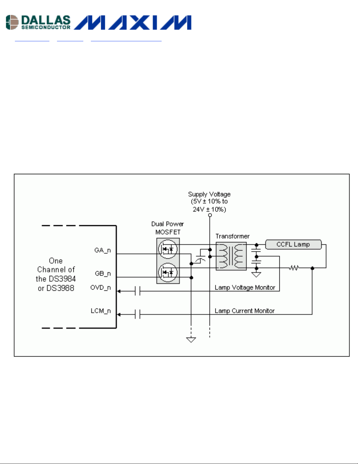
the CCFL lamps. Figure 1 details this arrangement.
Figure 1. DS3984 / DS3988 CCFL drive schematic.
Each channel of the controller drives two logic-level N-channel MOSFETs that are tied between the ends of a stepup transformer and ground. The transformer has a center tap on the primary that is connected to the DC supply.
The controller alternately turns on the two MOSFETs to create the high voltage AC waveform on the secondary.
The key variable in designing a push-pull drive scheme is selecting the turns ratio for the transformer. At a given
regulated lamp operating current, the transformer turns ratio is directly proportional to the CCFL lamp voltage
and inversely proportional to the DC supply voltage as shown in the equation below.
Page 2

For a given DC supply voltage, higher operating voltage CCFL lamps require a higher transformer turns ratio. For
a particular CCFL lamp, a higher DC supply voltage will require a lower transformer turns ratio. The operating
voltage of CCFL lamps varies, based on a number of factors including lamp diameter and length. Lamps with
smaller diameters and longer lengths operate at higher voltages.
There is not an exact formula for calculating the transformer turns ratio. Table 1 lists some empirically derived
transformer turns ratio for a variety of CCFL lamps. As can be seen from the table, the transformer turns ratio
decreases as the DC supply voltage increases, and the transformer turns ratio decreases as the operating voltage
of the CCFL lamps decreases.
Table 1. Target Transformer Turns Ratios for Various CCFL Lamps
Nominal DC
Supply Voltage
Lamp 1
2.4mm x 438mm
2
830 ~ 890 Vrms
Lamp 2
2.2mm x 258mm
1
540 ~ 600 Vrms
1
5V 80:1 70:1 65:1
6V 75:1 65:1 60:1
7V 70:1 60:1 55:1
8V 65:1 65:1 50:1
9V 60:1 50:1 45:1
10V 55:1 45:1 40:1
11V 50:1 40:1 36:1
12V 45:1 36:1 32:1
13V 40:1 32:1 30:1
14V 38:1 30:1 28:1
15V 36:1 28:1 26:1
16V 34:1 26:1 25:1
17V 32:1 25:1 24:1
18V 30:1 24:1 23:1
19V 29:1 23:1 22:1
20V 28:1 22:1 21:1
21V 27:1 21:1 20:1
22V 26:1 20:1 19:1
23V 25:1 19:1 18:1
24V 24:1 18:1 17:1
Lamp 3
2.0mm x 218mm
440 ~ 490 Vrms
1
Notes: 1. Lamp operating voltage at 5mArms operating current.
2. Assumes ±10% supply variation.
Users can select the proper turns ratio by using Table 1 as a guide. For example, to select the transformer turns
ratio to drive a CCFL lamp with a nominal operating voltage of 800V with a 24V supply, first use Table 1 to locate
the target transformer turns ratio for a comparable lamp. The 2.4mm x 438mm lamp listed in Table 1 most
closely matches the target lamp so a target 24:1 turns ratio would be selected. The actual turns ratio can vary by
±15% since the controller will automatically adjust to match the lamp.
Page 3

Design Hint: When estimating the transformer turns ratio, it is always advisable to keep the
turns ratio slightly high. The controller can make adjustments for a transformer turns ratio that is
slightly too high by reducing the MOSFET duty cycle but a transformer turns ratio that is too low
may not allow the lamp to strike.
Once a transformer turns ratio is selected, it should be tested with the target lamp over the operating DC supply
voltage range and temperature range. The resulting nominal duty cycles at the MOSFET gate driver pins (GA and
GB) should be measured. A well matched lamp to transformer design will result in duty cycles in the 25% to 35%
range.
Definition: Transformer Turns Ratio
This application note defines the transformer turns ratio as the number of secondary turns divided by the sum of
the two primary turns. For example, a 50:1 transformer may have 2100 secondary turns with two primary
windings of 21 turns each [2100/(21+21) = 50].
In addition to the transformer turns ratio, there are a number of other important transformer specifications that
are listed in Table 2. See the DS3984 and DS3988 data sheets for more details.
Table 2. Key Transformer Specifications
Parameter Test Condition Min Typ Max Unit
Frequency 40 80 Khz
Output Power 6 W
Output Current 5 8 mArms
Primary DCR center tap to one end 200 mohms
Secondary DCR 500 ohms
Primary Leakage 12 µH
Secondary Leakage 185 mH
Primary Inductance 70 µH
Secondary Inductance 500 mH
Secondary Output Voltage 100ms minimum 2000 Vrms
Secondary Output Voltage continuous 1000 Vrms
Application Note 3375: http://www.maxim-ic.com/an3375
More Information
For technical questions and support:
For samples:
Other questions and comments:
http://www.maxim-ic.com/samples
http://www.maxim-ic.com/support
http://www.maxim-ic.com/contact
Page 4

Related Parts
DS3881:
QuickView -- Full (PDF) Data Sheet -- Free Samples
DS3882:
DS3984:
DS3988:
DS3992:
DS3994:
QuickView -- Full (PDF) Data Sheet -- Free Samples
QuickView -- Full (PDF) Data Sheet -- Free Samples
QuickView -- Full (PDF) Data Sheet -- Free Samples
QuickView -- Full (PDF) Data Sheet
QuickView -- Full (PDF) Data Sheet
AN3375, AN 3375, APP3375, Appnote3375, Appnote 3375
Copyright © 2005 by Maxim Integrated Products
Additional legal notices: http://www.maxim-ic.com/legal
 Loading...