

Page 1
25
It is impossible to eliminate the leak current perfectly. There is
an effect that a stray capacitance decreases the lighting start voltage.
Therefore, it is recommended to decrease the leak current to the
possible level in consideration of matching with Inverter.
Leak current Is = 2π fCsVL
(1) By lowering the driving frequency f
If the driving frequency f is made too low, electric discharge
becomes unstable and the luminance is decreased. In consideration
of the luminance efficiency of the lamp, 50- 60 kHz is currently
prevalent. As the lamp diameter is smaller, it is necessary to raise
the frequency for stable lighting.
(2) By reducing the stray capacitance Cs
Cs = S/d
Widen the distance "d" between the high voltage wiring / lamp
and the conductor portion (reflector, chassis etc.).
For example, a non-conductive reflector should be reviewed.
It is to be noted, however, that the metallic reflector has an
effect of lowering the lighting start voltage.
(3) By reducing the Lamp Voltage VL
(Reducing the lamp impedance)
The lamp voltage depends on the CCFL characteristics.
As the CCFL is thinner and longer, the lamp voltage becomes
higher. As the gas pressure is higher, the impedance tends to be
higher.
How to reduce the leak current
[Appendix] How to measure leak current
(I
LeakRMS
)
FG
Lo
Hi
(I
LRMS
)
GND
(I
L
WLo
)
mA
mA
LCD panel
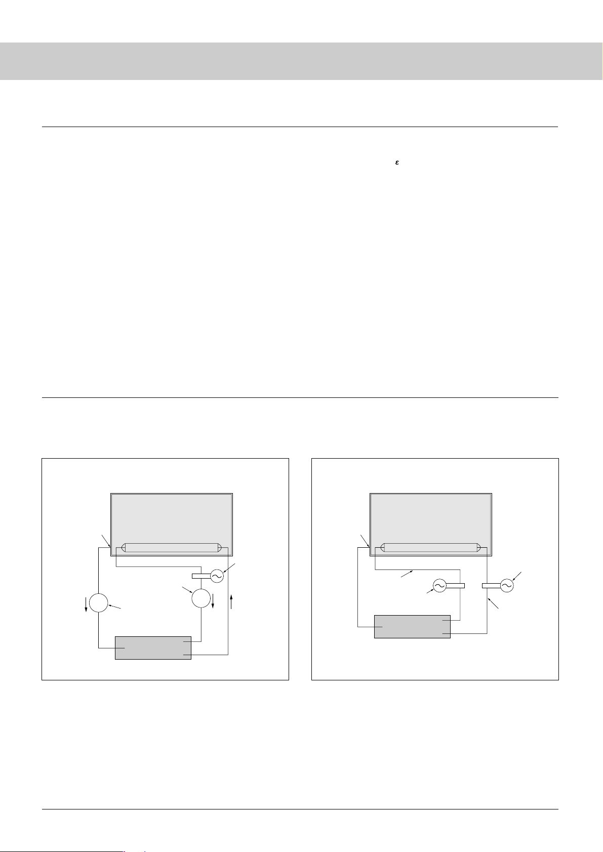
■ Case A: recommended ■ Case B: not recommendable
Lamp
Current probe
RMS ammeter
(Thermo-couple type)
RMS ammeter
(Thermo-couple type)
Inverter
I
L
(Lo side)
I
L
(Hi side)
FG
Lo
Hi
GND
LCD Panel
Lamp
Current probe
Inverter
(I
L
WLo
)
Current probe
(I
L
WHi
)
I
L
(Lo side)
I
L
(Hi side)
I
Leak
Inverter current
As a measuring method of the lamp current, please see “Case
A” which is recommendable and “Case B” (not recommendable) as
follows.
The measurement point of current is shown.
Page 2

26
Resistance
component
Voltage
Current phase
90°
270°
0°
180°
34.3°
I
Leak
= 4.1mA
I
L
(Hi side)
I
L
(Lo side) = 6mA
Resistance component of Lamp
(Lamp current)
Fig. 27
Fig. 28
Inverter current = 7.3mA
Capacitance component of panel
(Leak current)
Capacitance
component
Inductance
component
● Case A
Measure the lamp current and leak current with the RMS
ammeter (Thermo-couple type). This is because the ammeter
value is more accurate than the calculated value of the
oscilloscope. The oscilloscope is used for checking the lamp
current waveform (Crest & Imbalance Factor).
● Case B
This is a measuring method in which the difference between high
side (IL) and low side (IL) is deemed as leak current {IL(Hi) –
IL(LO)}. However, the accurate leak current cannot be obtained,
because the current value (Hi side IL) is the value of the
synthesized current (IL+I leak).
(Not scalar, but the sum of vector should be used.)
● For your reference, let us explain the synthesis of the vector
of Fig. 27.
The sum of vector of lamp current and the leak current is
equivalent to the current of the inverter.
The phase of inverter current advances against lamp current about
34.3° due to the influence of the C component of the panel.
As a result, inverter current, lamp current and leak current will be
7.3 mA, 6mA and 4. 1mA respectively.
This is expressed by the following equation:
Inverter Current 7.3 mA
Lamp Current 6 mA
Leak Current 4.1 mA
Inverter current [IL (Hi side)] = (I
Leak
)2+ (I
L
(Lo side))
2
= (4.1mA)2+ (6mA)
2
= 7.3 mA
● Incidentally, refer to Fig. 28 for the difference between the
voltage phase and the current phase.
The phase difference is 0 for component R (resistance), delays
90° for L component (coil) and advances 90° for component C
(capacitor).
CCFL
 Loading...