

Page 1
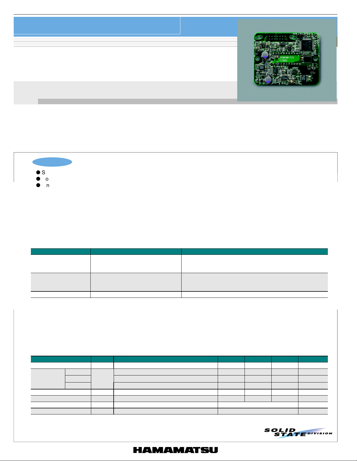
IMAGE SENSOR
Driver circuit for NMOS linear image sensor
C7885 series
Driver circuit for voltage-output type NMOS linear image sensor
C7885 series is a driver circuit specifically designed for the Hamamatsu voltage-output type NMOS linear image sensors (S3921 to S3924
series). NMOS linear image sensors are self-scanning photodiode arrays integrated with a scanning circuit of N-channel MOS transistors.
C7885 series supplies start pulses, 2-phase clock pulses and reset pulses necessary for voltage-output type image sensor operation. C7885
series also includes a signal processing circuit that inverts and amplifies video signals from an image sensor. C7885 series operates by input of a
master start pulse, master clock pulse and connection to a power supply (+12 V or +15 V).
C7885-20 is multichannel detector head incorporating driver circuit (C7885) developed for Hamamatsu NMOS linear image sensor. C7885-20 is
designed especially for compactness, having an overall length as short as 40 mm or less. The housing case also provides a shielding effect
against external noise. As useful options, peripheral devices are available for driving C7885-20, and for the output signal processing.
C7885
Features
l
Suitable for voltage-output type image sensors
l
Compact (compared to conventional type C4074)
l
Single power supply (+12 V or +15 V) operation
■ Selection guide
Type No. Product name Feature
High-speed driver circuit for voltage-output type NMOS
C7885 Driver circuit
C7885G Driver circuit + Pulse generator
C7885-20 Multichannel detector head C7885 driver circuit board is installed in a shield case.
Note)
1: Standard input/output connector is FAP-16-07#2 (made by Yamaichi, sold separately). Equivalent connectors are available
from other manufacturers.
2: Custom products with an input/output connector pre-mounted are available on request. Please consult our sales office.
3: When ordering along with a dedicated cable (A8226), C7885 will be
4: We welcome custom requests. Feel free to contact our sales office.
5: When using current-output type NMOS linear image sensors, refer to C7883/C7884 series data sheets.
linear image sensors.
Has no input/output connector.
A dedicated pulse generator is pre-mounted on the driver
circuit board.
Has no input/output connector.
shipped with a mating connector pre-mounted.
■ Specifications (Ta=25 °C)
Parameter Symbol Condition Min. Typ . Max. Unit
Supply voltage +Vs +11.5 +12.0 +15.5 V
Current
consumption
Operation frequency - Master clock frequency: 3 MHz - - 500 kHz
Gain G - 6 - V/pC
Operating temperature Topr 0 to +50 * °C
Storage temperature Ts t g -10 to +60 * °C
* No condensation
C7885 +12 V - 30 40 mA
C7885G +12 V - 60 80 mA
C7885-20
+Is
+12 V - 30 40 mA
1
Page 2
Driver circuit for NMOS linear image sensor
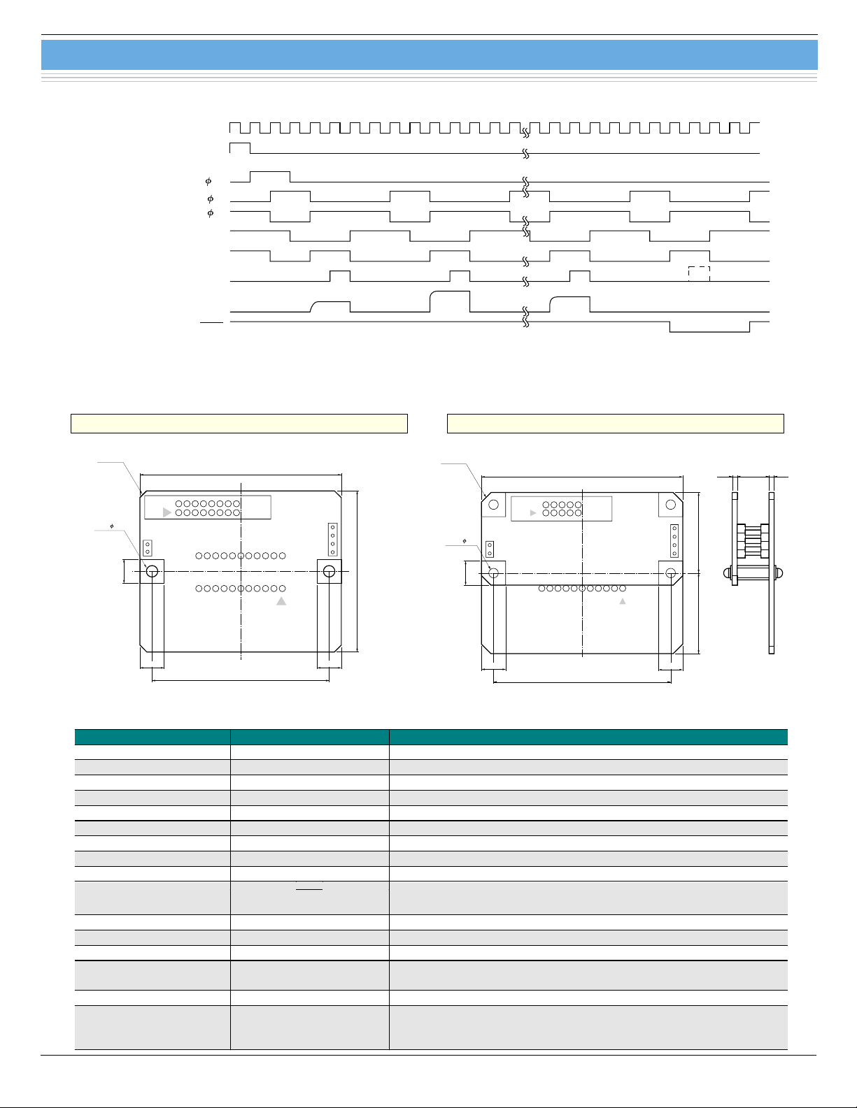
■ Timing chart
MASTER CLOCK CLK
MASTER START Start
START st
CLOCK 1
CLOCK 2
RESET
CLAMP
Trigger
VIDEO OUTPUT Data Video
END OF SCAN EOS
■ Dimensional outlines and input/output signal descriptions (unit: mm)
C7885 series
KACCC0120EA
C7885
(4 ×) C3
(2 ×) 3.6
7.62
7.62
2
1
63.5
55.88
16
15
50.8
7.62
KACCA0086EA
Te rm in a l N o . Terminal name Description
1 A. GND Analog ground
2 +12 V or +15 V Power supply
3 A. GND Analog ground
4 NC No connection
5 A. GND Analog ground
6 Data Video Analog video signal output; positive polarity
7 A. GND Analog ground
8 A. GND Analog ground
9 D. GND Digital ground
(4 ×) C3
(2 ×) 3.6
7.62
7.62
C7885G
63.5
55.88
1.6 10.0 1.6
25.4 25.4
7.62
KACCA0106EA
10
EOS
Digital output signal indicating end of scan; negative logic
11 D. GND Digital ground
12 Trigger Digital output signal for A/D conversion; positive logic
13 D. GND Digital ground
14 CLK
Digital input signal for operating the circuit at the rising edge (in case of
C7885G, output signal)
15 D. GND Digital ground
Digital input signal for initializing the circuit; positive logic. (in case of
16 Start
C7885G, output signal)
Interval of these pulses equals the integration time of the sensor.
2
Page 3
Driver circuit for NMOS linear image sensor
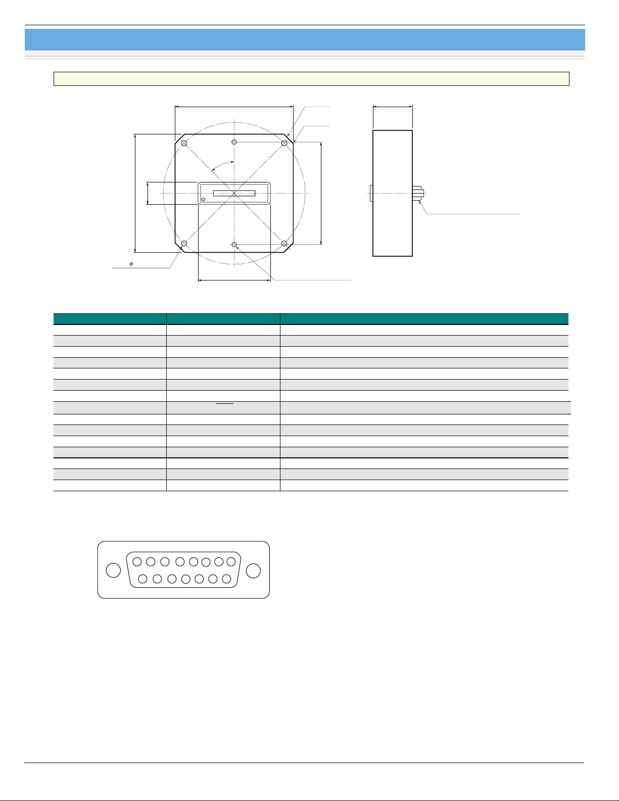
C7885-20
C7885 series
(4 ×) C7
(8 ×) R3
65.0
(2 ×) M3
EFFECTIVE LENGTH 10
25.0
D-SUB 15 PIN SOCKET TYPE
75.0
14.0
90PCD
(4 ×) 3.5 PIERCE
75.0
45.0
46.0
Te rm in a l N o . Terminal name Description
1 NC No connection
2 Data video Analog video signal output; positive polarity
3 +12 V (+15 V) Positive power supply
4 NC No connection
5 NC No connection
6 Start Digital input signal for initializing the current; positive logic
7 CLK Digital input signal for operating the circuit at the rising edge
8
EOS
Digital output signal indicating end of scan; negative logic
9 A. GND Analog ground
10 A. GND Analog ground
11 Shield Case shield
12 D. GND Digital ground
13 D. GND Digital ground
14 D. GND Digital ground
15 Trigger Digital output signal for A/D conversion; positive logic
KACCA0112EA
■ Pin assignment of “Signal I/O” connector (C7885-20, 15 pin D-sub socket type)
2345678
1
131415
9101112
KACCC0069EA
3
Page 4
Dedicated cable
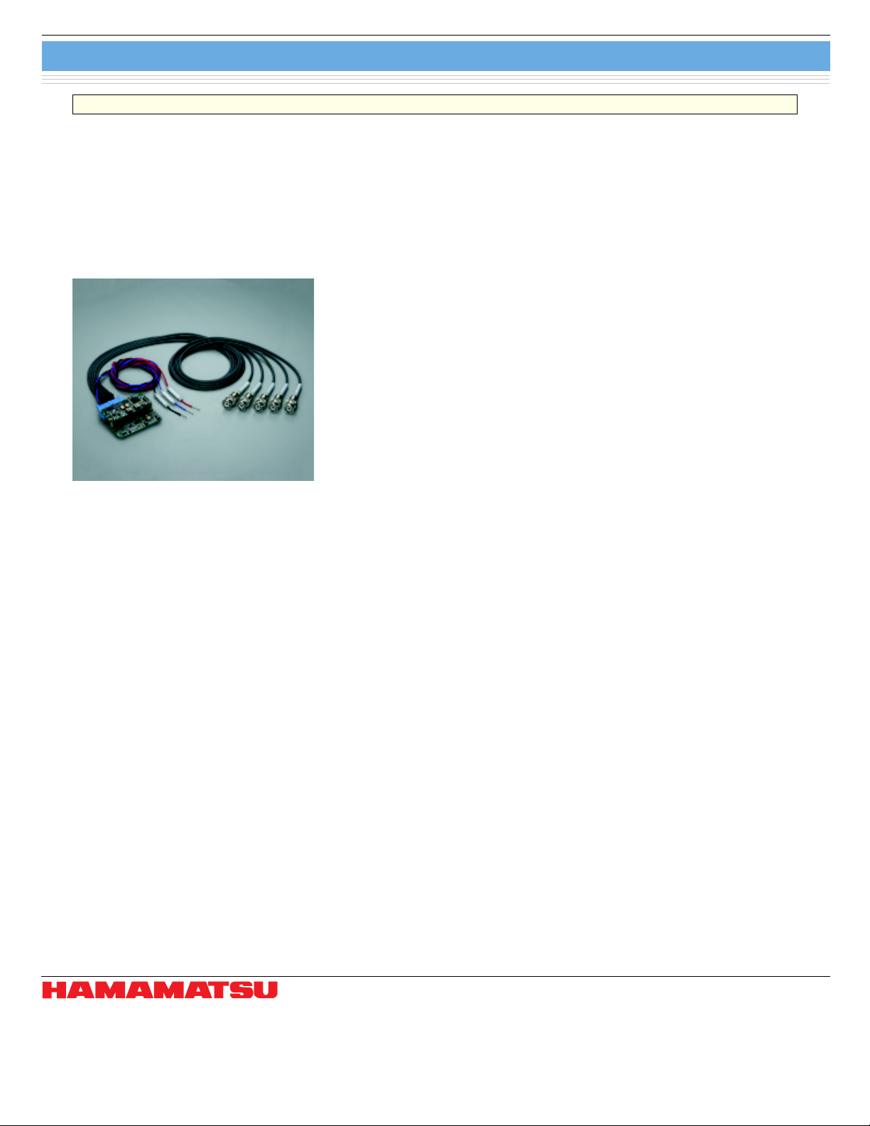
A8226
Dedicated cable A8226
Connector on board: UFS-16B-01
Input/output signal connector: BNC (Start, CLK, Trigger, EOS, Data Video)
Power supply: lose wire cable
Cable length: 1 m
Note) When making a simple in-circuit evaluation of NMOS linear image sensors without any troublesome soldering, use
C7883G, C7884G, C7884G-01 or G7885G in combination with A8226.
All you have to do is just insert an NMOS linear image sensor into the socket and connect the cables to an oscilloscope,
power supply and AD converter. Note that NMOS linear image sensors are sold separately.
C7884G used in combination with A8226
Information furnished by HAMAMATSU is believed to be reliable. However, no responsibility is assumed for possible inaccuracies or omissions.
HAMAMATSU PHOTONICS K.K., Solid State Division
1126-1 Ichino-cho, Hamamatsu City, 435-8558 Japan, Telephone: (81) 053-434-3311, Fax: (81) 053-434-5184, http://www.hamamatsu.com
U.S.A.: Hamamatsu Corporation: 360 Foothill Road, P.O.Box 6910, Bridgewater, N.J. 08807-0910, U.S.A., Telephone: (1) 908-231-0960, Fax: (1) 908-231-1218
Germany: Hamamatsu Photonics Deutschland GmbH: Arzbergerstr. 10, D-82211 Herrsching am Ammersee, Germany, Telephone: (49) 08152-3750, Fax: (49) 08152-2658
France: Hamamatsu Photonics France S.A.R.L.: 8, Rue du Saule Trapu, Parc du Moulin de Massy, 91882 Massy Cedex, France, Telephone: 33-(1) 69 53 71 00, Fax: 33-(1) 69 53 71 10
United Kingdom: Hamamatsu Photonics UK Limited: 2 Howard Court, 10 Tewin Road, Welwyn Garden City, Hertfordshire AL7 1BW, United Kingdom, Telephone: (44) 1707-294888, Fax: (44) 1707-325777
North Europe: Hamamatsu Photonics Norden AB: Smidesvägen 12, SE-171 41 Solna, Sweden, Telephone: (46) 8-509-031-00, Fax: (46) 8-509-031-01
Italy: Hamamatsu Photonics Italia S.R.L.: Strada della Moia, 1/E, 20020 Arese, (Milano), Italy, Telephone: (39) 02-935-81-733, Fax: (39) 02-935-81-741
Specifications are subject to change without notice. No patent rights are granted to any of the circuits described herein. ©2002 Hamamatsu Photonics K.K.
4
Cat. No. KACC1076E01
Apr. 2002 DN
 Loading...