

Page 1
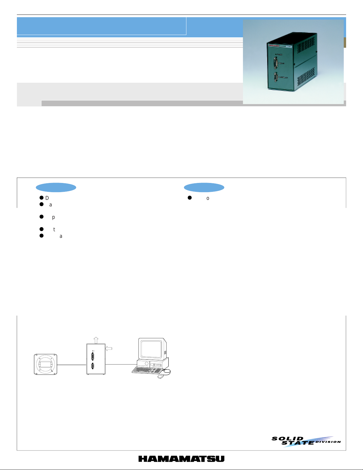
IMAGE SENSOR
Multichannel detector head controller
C7557
For control of multichannel detector head and data acquisition
C7557 is specifically designed for basic control in multichannel photometry. When connected to a Hamamatsu multichannel detector head and a
personal computer, C7557 allows easy control of the detector head and data acquisition by using dedicated software that comes with the unit.
C7557 supports all models of Hamamatsu multichannel detector heads designed to use a CCD image sensor or InGaAs image sensor. C7557
provides various useful functions (see page 2) that efficiently collect sample data during basic operation.
C7557 controller includes a driver/amplifier circuit for operating a multichannel detector head, a power supply circuit, a temperature stabilizer
circuit, an A/D conversion circuit that converts analog signals from the detector head into digital signals, and a data interface.
The software supplied with C7557 allows easy control of the multichannel detector head and data acquisition through the SCSI interface. This
software runs on Windows 95/98/Me, by simple operation from the menu neatly displayed on the screen. This software is available with different
kinds of DLL*
*1: DLL is one of useful functions the Windows 95/98/Me. It is a library that can freely start up from application software or execute function
procedure. Software development can be made easier with DLL. To use DLL, see the operation manual that comes with the unit.
1
to help you develop your own software programs under various developmental environments.
Features
l
Designed for basic control in multichannel photometry
l
Easy to control multichannel detector head and data
acquisition
l
Supports all models of Hamamatsu multichannel
detector heads (CCD, InGaAs)
l
Software with different kind of DLL is supplied with C7557
l
Compact configuration
■ Connections to detector head and PC
POWER
SIGNAL I/O
TE CONTROL I/O
1
Trig.
2
SCSI *
CABLE
SHUTTER *
TIMING PULSE
DEDICATED CABLE
(WITH C7557)
Applications
l
Control of multichannel detector head and data acquisition
IMAGE SENSOR
+
MULTICHANNEL
DETECTOR HEAD
C7557
PERSONAL COMPUTER (PC/AT)
(INTEGRATED SCSI BOARD)
*1: Shutter, etc. are not available.
*2: SCSI cable and SCSI board (card) are not supplied with C7557.
KACCC0077EB
1
Page 2
Multichannel detector head controller
C7557
■ Functions
Data transfer Transfers data stored in memory to computer.
Exposure time setting
External sync signal input BNC connector input
Trigger mode Internal sync, external sync
Trigger polarity Trigger polarity selectable for external sync
Shutter timing pulse output
Video signal output Outputs video signal sent from head, via BNC connector.
Video sync signal output
Amplifier gain 1/2, 1, 2, 5, 10, 20, 50, 100
Detector head
Number of detector channels
Detector cooling control Cooling start and stop
Detector cooling temperature readout
Parameter Specification
1 ms to 65535 ms (1 ms steps)
Minimum exposure time depends on sensor detection level.
Outputs timing signal for operating external shutter or external light source via BNC connector.
Pulse width, delay and polarity settings are possible.
Outputs sync signal used to observe video signal output with external device such as
oscilloscope, via BNC connector.
Refer to ■SELECTION GUIDE FOR IMAGE SENSOR AND DETECTOR HEAD COMBINATION
Converts analog temperature data from detector into digital signal, and transfers it to computer
(10 bit A/D conversion)
■ Specifications
AD converter
●
AD converter 16 bits 12 bits 16 bits
Conversion speed 4 µs/ch 2 µs/ch 8 µs/ch
Input range 0 to 10 V -10 to +10 V
Input method Differential input
Nonlinear linearity 0.1 %FS
AD conversion signal External input
Parameter CCD area image sensor InGaAs linear image sensor
Controller
●
Clock 20 MHz
Memory 4 MB (1024 ch × 2048 lines)
Interface SCSI
Equipment
●
Interface SCSI: 50-pin half pitch connector
Power supply AC100 to 240 V ± 10 %, 50 to 60 Hz
Power consumption 33 W Max.
Outline dimension
Operating temperature 0 to 40 °C
Storage temperature -10 to 50 °C
Weight Approx. 2.9 kg
SCSI interface
●
SCSI boards manufactured by Adaptec, especially types below, are recommended.
PCI bus: AHA-2940AU, 2940U2W, 2940UW, SCSI CARD 2930U, 19160, PCMCIA: APA-1460A, 1480
Software
●
Compatible OS *
*3: This software may be run on Windows 2000, NT or XP with a simple task. For information on how to do this, please consult with our sales office.
Others
●
BNC cable is separately required when making measurements by external sync, controlling an external shutter or external light source, or
measuring the video signal with an external device.
Parameter Specification
Parameter Specification
92 (W) × 150 (H) × 225.8 (D) mm
Parameter Specification
3
Windows95, Windows98, Windows ME
2
Page 3
Multichannel detector head controller
C7557
■ Operation method
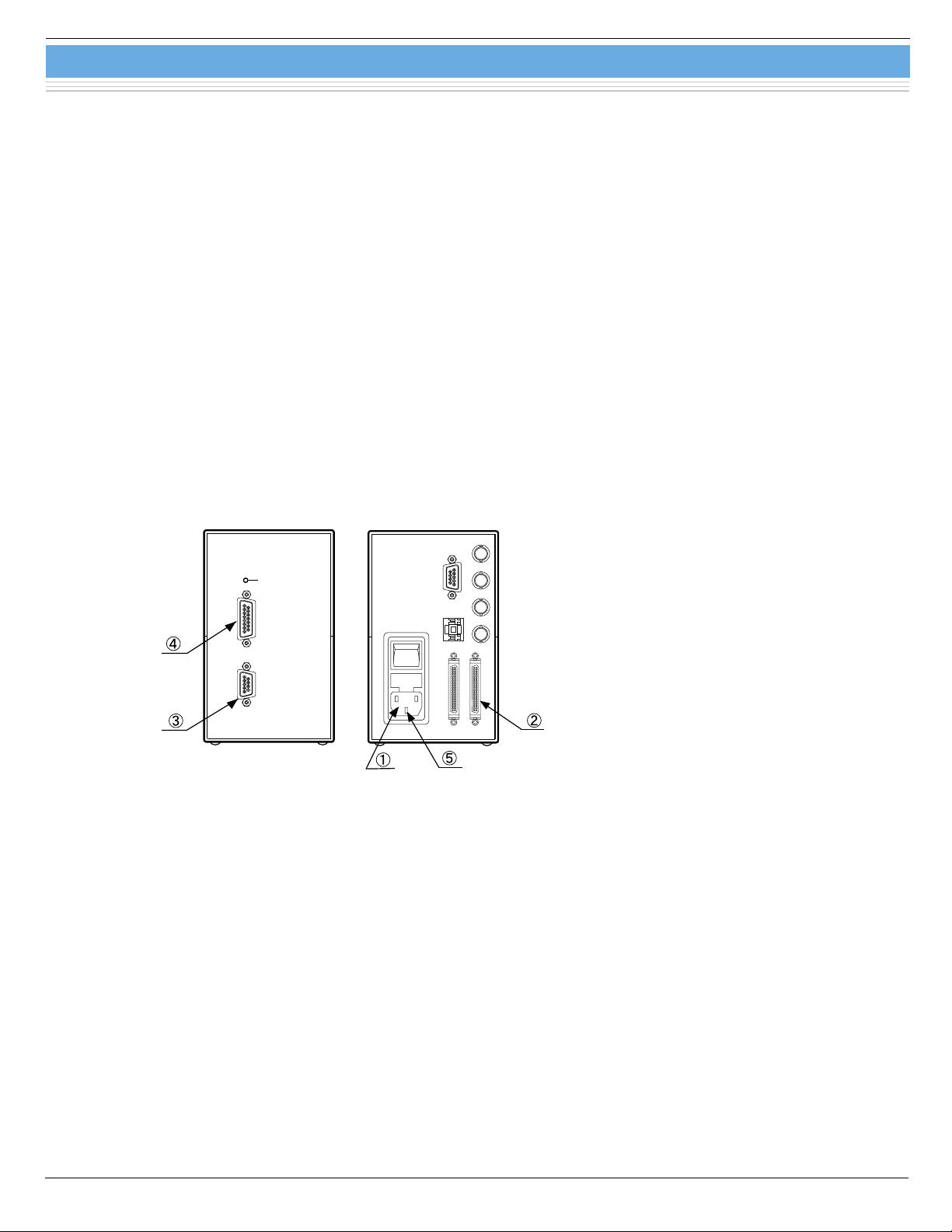
1. Make connections as indicated in ➀ to ➄.
➀ LINE Connect to the power cable.
➁ SCSI
➂ TE CONTROL I/O Connect to the "TE CONTROL I/O" terminal on the detector head.
➃ SIGNAL I/O Connect to the "I/O SIGNAL" terminal on the detector head.
➄ GND When a 2-pin AC plug is used with the power cable, use this GND connector to ground the unit.
2. When all the connections are complete, turn on the power to C7557.
3. Install the dedicated softeware. (For details on the dedicated software, refer to the operation manual supplied in the package.)
*4: A terminator must be plugged into the last unit in the SCSI chain.
*4
Connect to a computer through the SCSI interface cable. When C7557 is the last unit in the SCSI
chain, plug a teminator into another SCSI port on C7557.
POWER
SIGNAL I/O
TE CONTROL I/O
FRONT VIEW
RS-232C
SCSI ID
LINE
SCSI
REAR VIEW
TRIG.IN
PULSE OUT
VIDEO OUT
SYNC.OUT
KACCC0083EC
3
Page 4
Multichannel detector head controller
C7557
■ Software functions
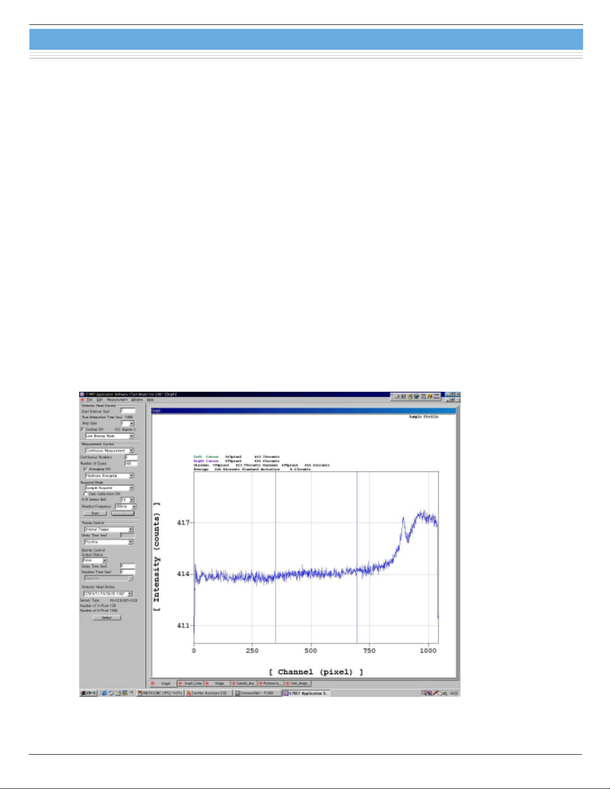
The figure below shows the main screen (CCD image sensor: line binning) while running on Windows 95/98/Me.
From the main screen menu, you can easily set operating conditions for the multichannel detector head and data acquisition
parameters. The measurement screen displayed with this software shows the image sensor channel along the horizontal axis
and the output count along the vertical axis. The main screen menu also allows you to select the desired operation mode: line
binning or area scanning (for CCD image sensors), or line scanning (for InGaAs image sensors).
The parameters that can be set on the main screen are as follows:
•Exposure time
•Amplifier gain
•Cooling control
•Number of integrations
•Dark correction
•Type of measurement data
•Start or end of measurement
•Detector head status
•Trigger mode
•Trigger polarity
•Shutter timing pulse width
•Shutter timing pulse delay
•Shutter timing pulse polarity
4
Page 5

Multichannel detector head controller
■ Selection guide for image sensor and detector head combination
Suitable multichannel
detector head
Type No. Type No. Number of active pixel
S7010-0906 512 × 60 12.288 × 1.440
S7010-0907 512 × 124 12.288 × 2.976
C7020
C7021
C7025
C7040
C7041
C7043
C7044
C7180 S7170-0909 512 × 512 12.288 × 12.288
C7181 S7171-0909 512 × 512 12.288 × 12.288
C8060-01
C8061-01
C8062-01
*5: C7557 can be used with following back-thinned CCD area image sensors and multichannel detector heads
Two-stage TE-cooled CCD S7032 series/multichannel detector head C7042
•
Two-stage TE-cooled CCD S7035 series/multichannel detector head C7045
•
Two-stage TE-cooled CCD S7172-0909/multichannel detector head C7182
•
S7010-0908 512 × 252 12.288 × 6.048
S7010-1006 1024 × 60 24.576 × 1.440
S7010-1007 1024 × 124 24.576 × 2.976
S7010-1008 1024 × 252 24.576 × 6.048
S7011-0906 512 × 60 12.288 × 1.440
S7011-0907 512 × 124 12.288 × 2.976
S7011-1006 1024 × 60 24.576 × 1.440
S7011-1007 1024 × 124 24.576 × 2.976
S7015-0908 512 × 252 12.288 × 6.048
S7015-1008 1024 × 252 24.576 × 6.048
S7030-0906 512 × 58 12.288 × 1.392
S7030-0907 512 × 122 12.288 × 2.928
S7030-0908 512 × 250 12.288 × 6.000
S7030-1006 1024 × 58 24.576 × 1.392
S7030-1007 1024 × 122 24.576 × 2.928
S7030-1008 1024 × 250 24.576 × 6.000
S7031-0906 512 × 58 12.288 × 1.392
S7031-0907 512 × 122 12.288 × 2.928
S7031-0908 512 × 250 12.288 × 6.000
S7031-1006 1024 × 58 24.576 × 1.392
S7031-1007 1024 × 122 24.576 × 2.928
S7031-1008 1024 × 250 24.576 × 6.000
S7033-0907 512 × 122 12.288 × 2.928
S7033-1007 1024 × 122 24.576 × 2.928
S7034-0907 512 × 122 12.288 × 2.928
S7034-1007 1024 × 122 24.576 × 2.928
G9201-256R 256 12.8 × 0.25
G9202-512R 512 12.8 × 0.25
G9203-256R 256 12.8 × 0.50
G9204-512R 512 12.8 × 0.50
G9201-256S 256 12.8 × 0.25
G9202-512S 512 12.8 × 0.25
G9203-256S 256 12.8 × 0.50
G9204-512S 512 12.8 × 0.50
G9211-256S 256 12.8 × 0.25
G9212-512S 512 12.8 × 0.25
G9213-256S 256 12.8 × 0.50
G9214-512S 512 12.8 × 0.50
G9205-256W 256 12.8 × 0.25
G9206-256W 256 12.8 × 0.25
G9207-256W 256 12.8 × 0.25
G9208-256W 256 12.8 × 0.25
Image sensor
Active area
[mm (H) × mm (V)]
C7557
Types of sensor
Front-illuminated
CCD area
image sensor
Back-thinned
CCD area
image sensor
InGaAs linear
image sensor
*5
5
Page 6

■ Dimensional outline (unit: mm)
Multichannel detector head controller
C7557
92 ± 2
POWER
SIGNAL I/O
150 ± 2
TE CONTROL I/O
2.2
FRONT VIEW SIDE VIEW REAR VIEW
■ Configuration
•C7557 main unit 1
•SCSI terminator 1
•Fuse (1.6 A) 1
•Detector head connection cables 2
•AC cable 1
•Software 1
•Operation manual 1
226 ± 2
LINE
RS-232C
SCSI ID
SCSI
TRIG.IN
PULSE OUT
VIDEO OUT
SYNC.OUT
KACCA0061EC
■ Caution
SCSI cable and SCSI board (card) are not supplied with C7557.
Information furnished by HAMAMATSU is believed to be reliable. However, no responsibility is assumed for possible inaccuracies or omissions.
HAMAMATSU PHOTONICS K.K., Solid State Division
1126-1 Ichino-cho, Hamamatsu City, 435-8558 Japan, Telephone: (81) 053-434-3311, Fax: (81) 053-434-5184, http://www.hamamatsu.com
U.S.A.: Hamamatsu Corporation: 360 Foothill Road, P.O.Box 6910, Bridgewater, N.J. 08807-0910, U.S.A., Telephone: (1) 908-231-0960, Fax: (1) 908-231-1218
Germany: Hamamatsu Photonics Deutschland GmbH: Arzbergerstr. 10, D-82211 Herrsching am Ammersee, Germany, Telephone: (49) 08152-3750, Fax: (49) 08152-2658
France: Hamamatsu Photonics France S.A.R.L.: 8, Rue du Saule Trapu, Parc du Moulin de Massy, 91882 Massy Cedex, France, Telephone: 33-(1) 69 53 71 00, Fax: 33-(1) 69 53 71 10
United Kingdom: Hamamatsu Photonics UK Limited: 2 Howard Court, 10 Tewin Road, Welwyn Garden City, Hertfordshire AL7 1BW, United Kingdom, Telephone: (44) 1707-294888, Fax: (44) 1707-325777
North Europe: Hamamatsu Photonics Norden AB: Smidesvägen 12, SE-171 41 Solna, Sweden, Telephone: (46) 8-509-031-00, Fax: (46) 8-509-031-01
Italy: Hamamatsu Photonics Italia S.R.L.: Strada della Moia, 1/E, 20020 Arese, (Milano), Italy, Telephone: (39) 02-935-81-733, Fax: (39) 02-935-81-741
Specifications are subject to change without notice. No patent rights are granted to any of the circuits described herein. ©2003 Hamamatsu Photonics K.K.
6
Cat. No. KACC1041E04
Sep. 2003 DN
 Loading...